Builds Cummins R2.8 H151 Swap into 1993 FZJ80

This site may earn a commission from merchant affiliate
links, including eBay, Amazon, Skimlinks, and others.

I investigated the bumpstops a bit today. I have been paying close attention to my oilpan clearance and I want to be sure that no accidents will occur down the road in the middle of nowhere.

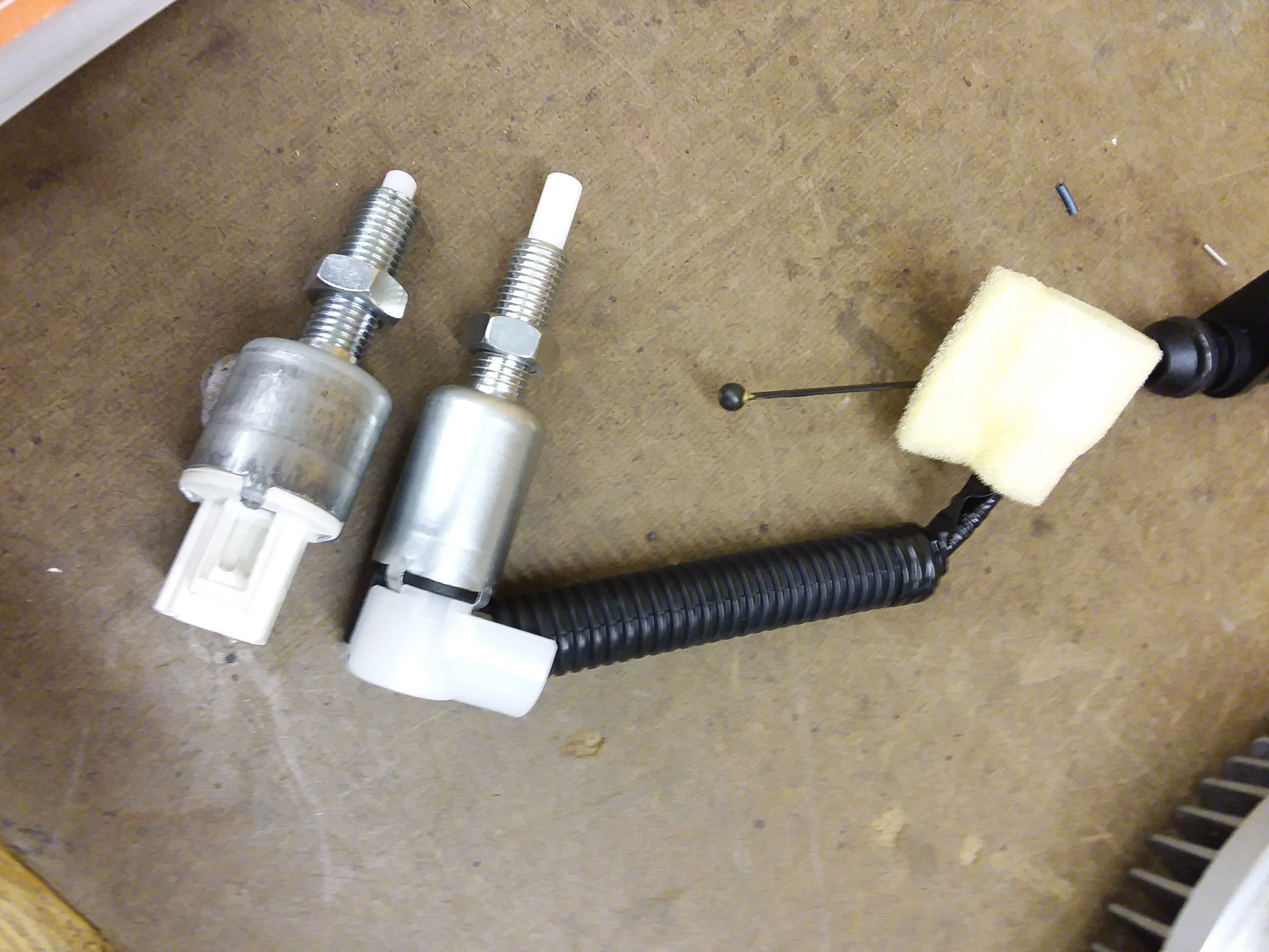
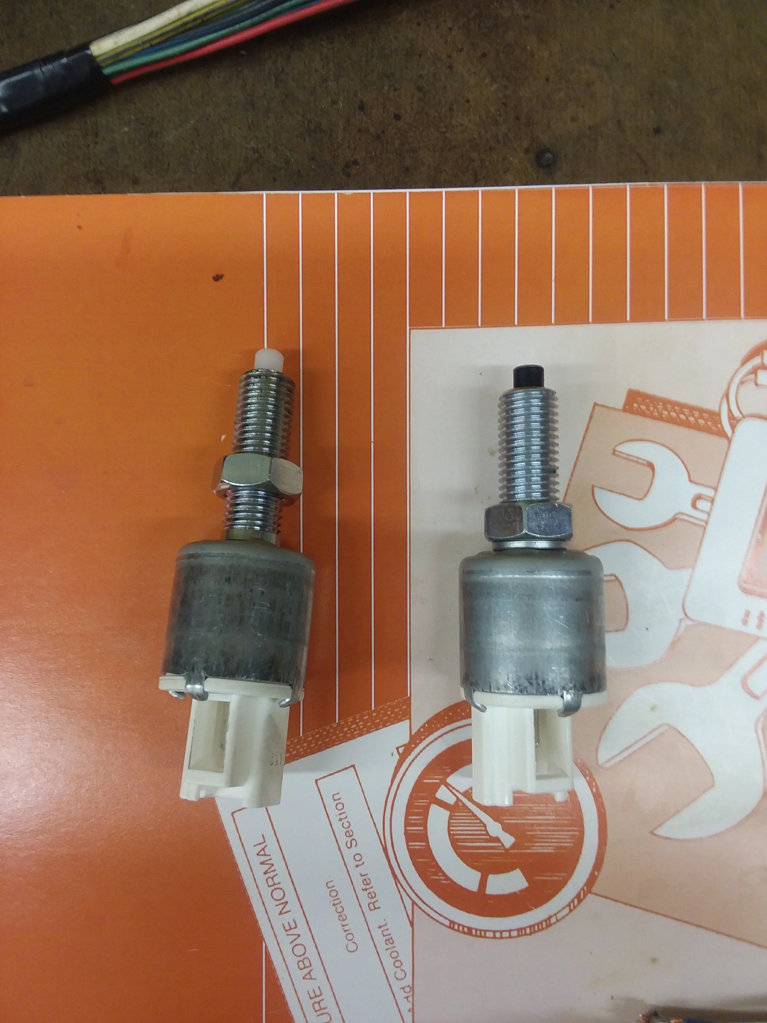
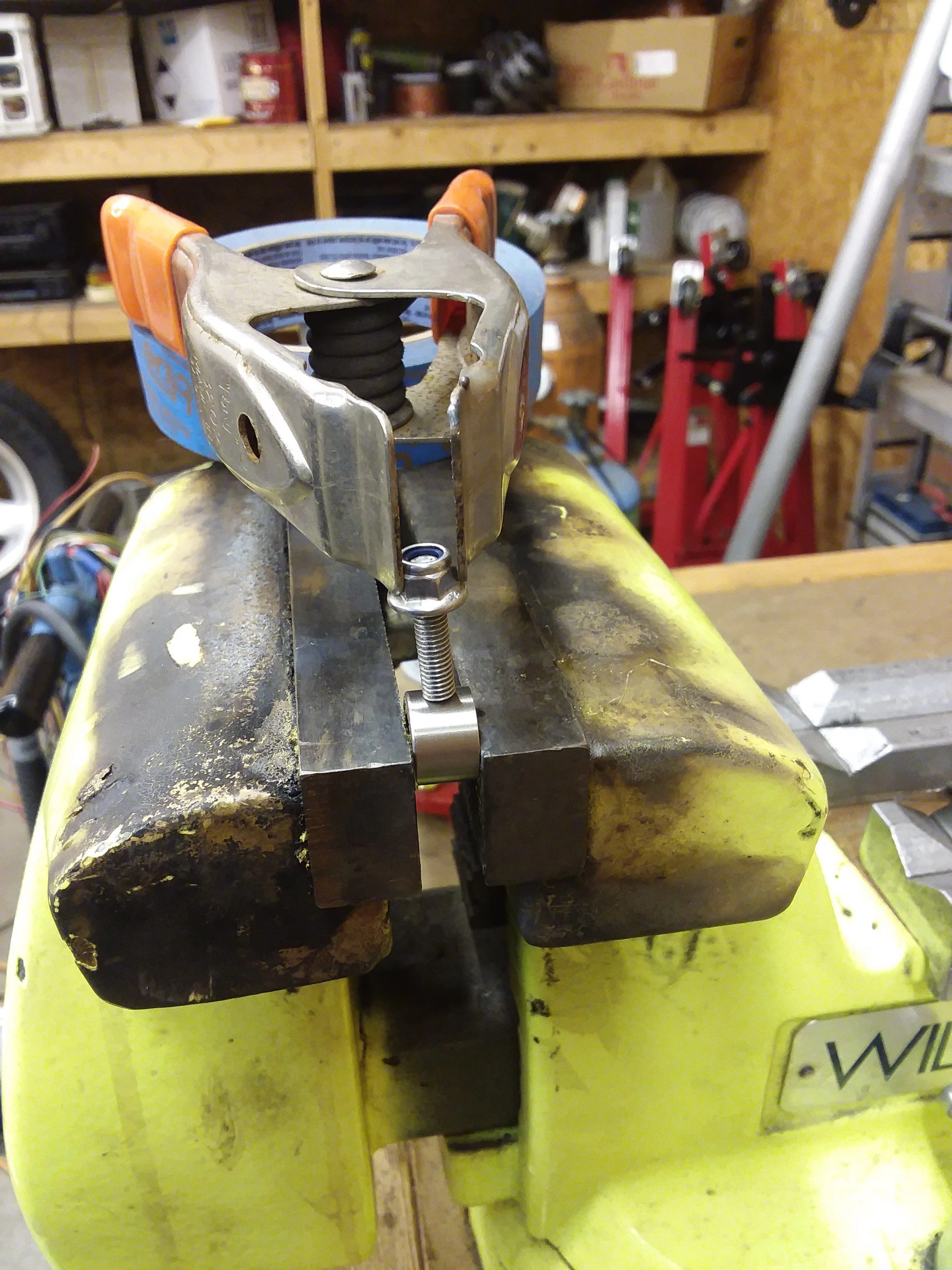
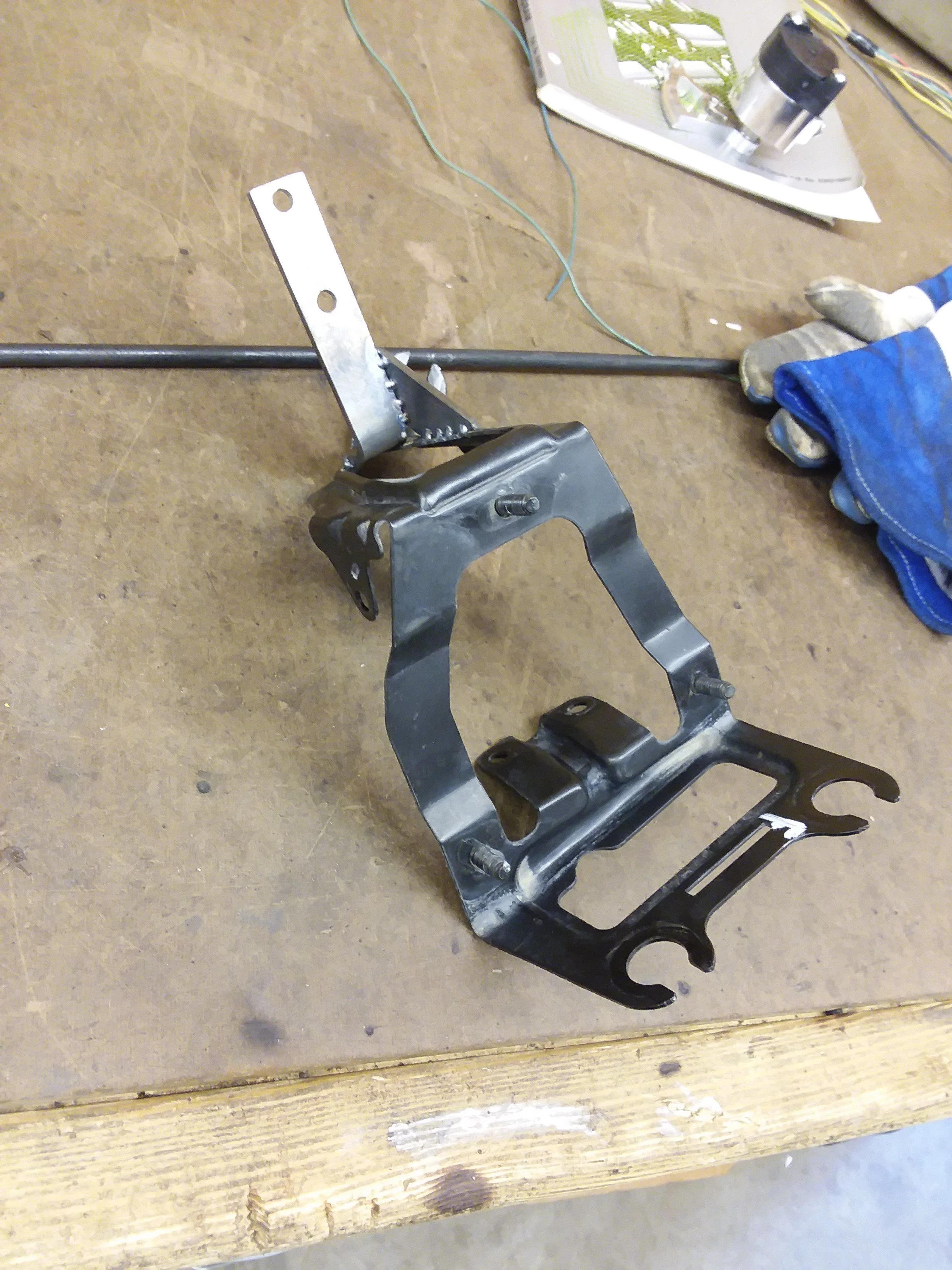
First, here are the inboard stops, they are not the same but both appear to have 10 digit part numbers on them, OEM?


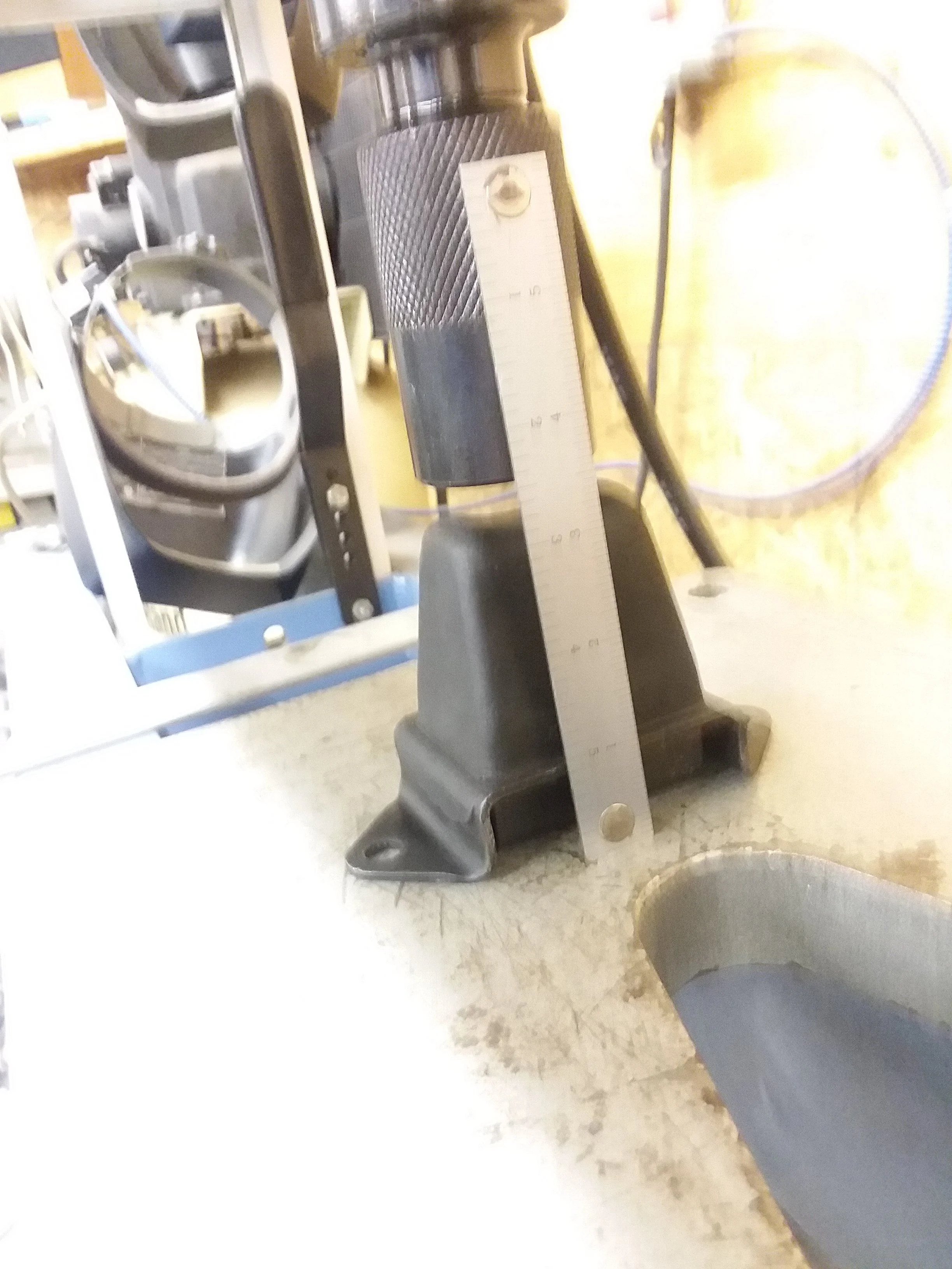
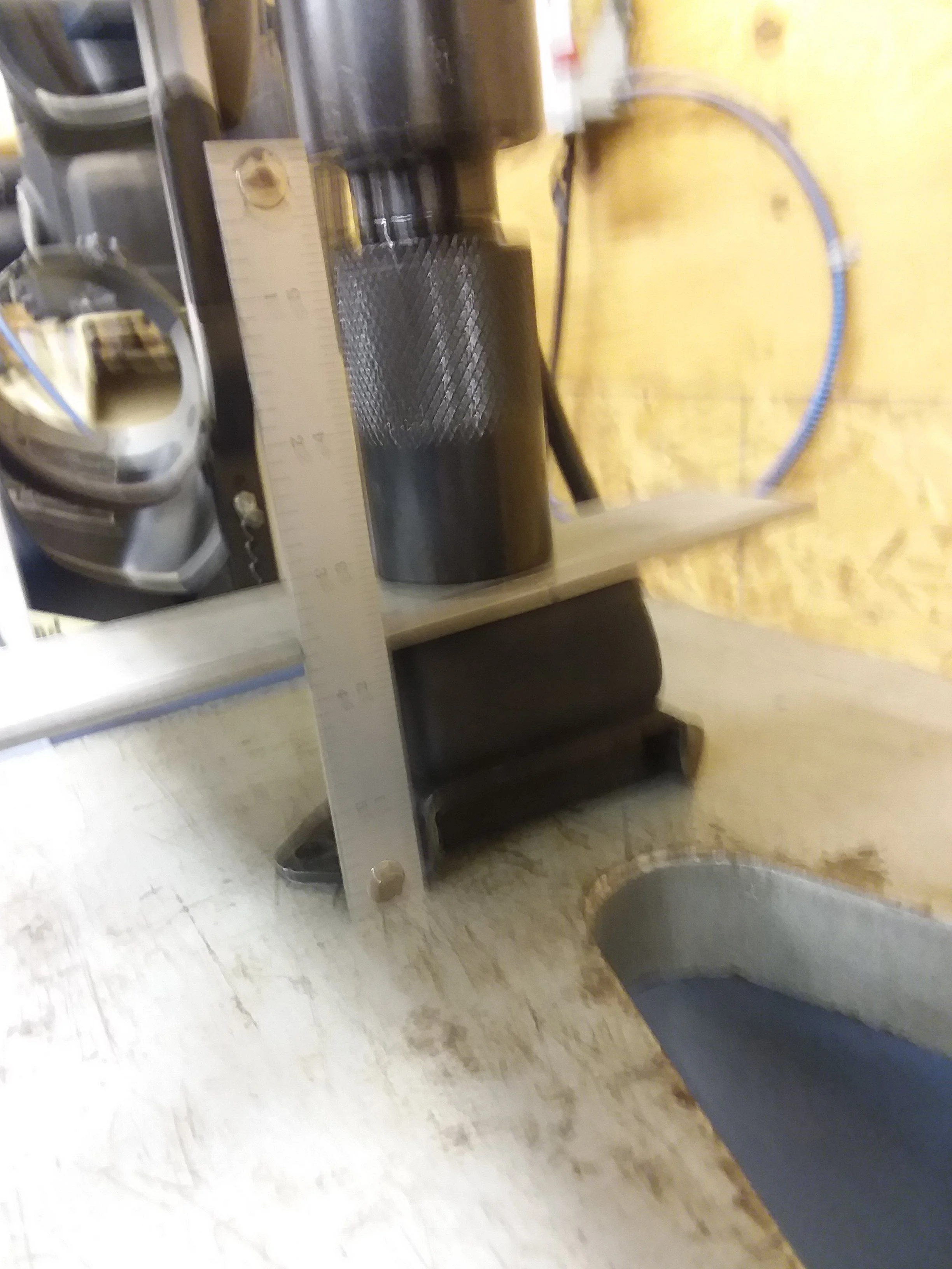
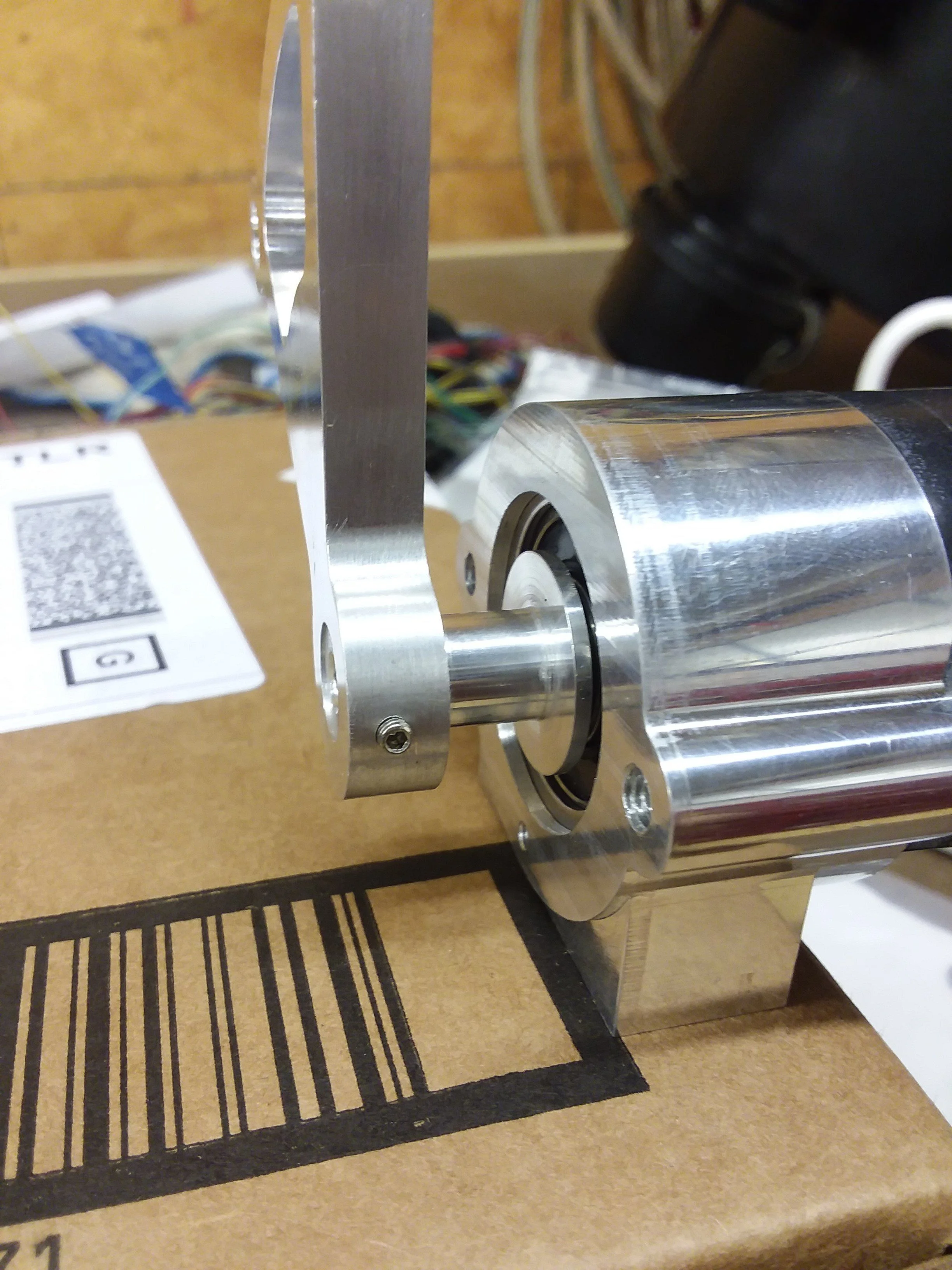
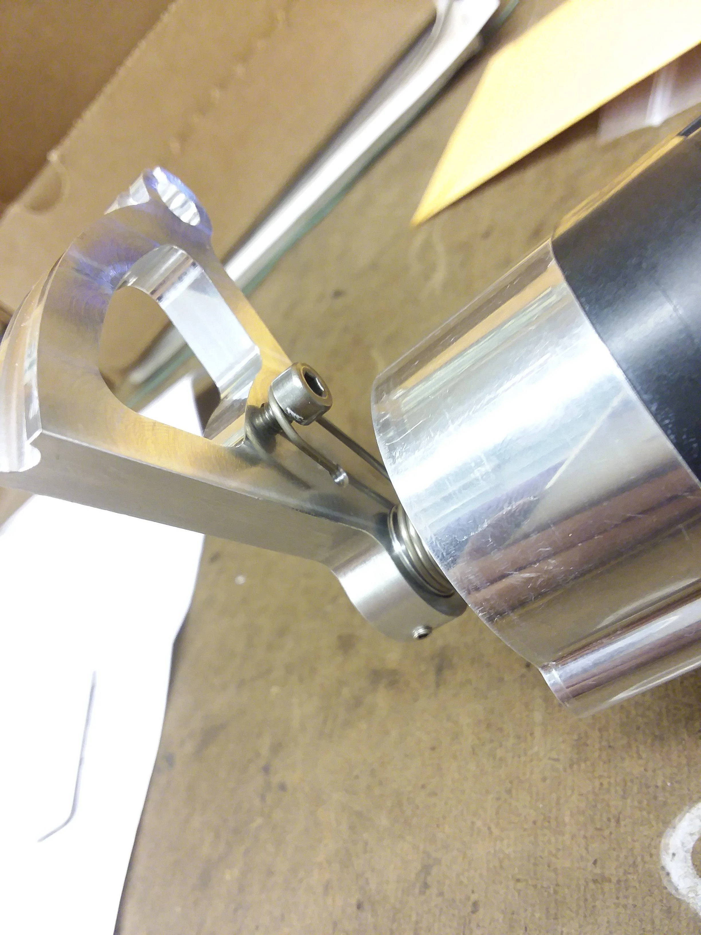
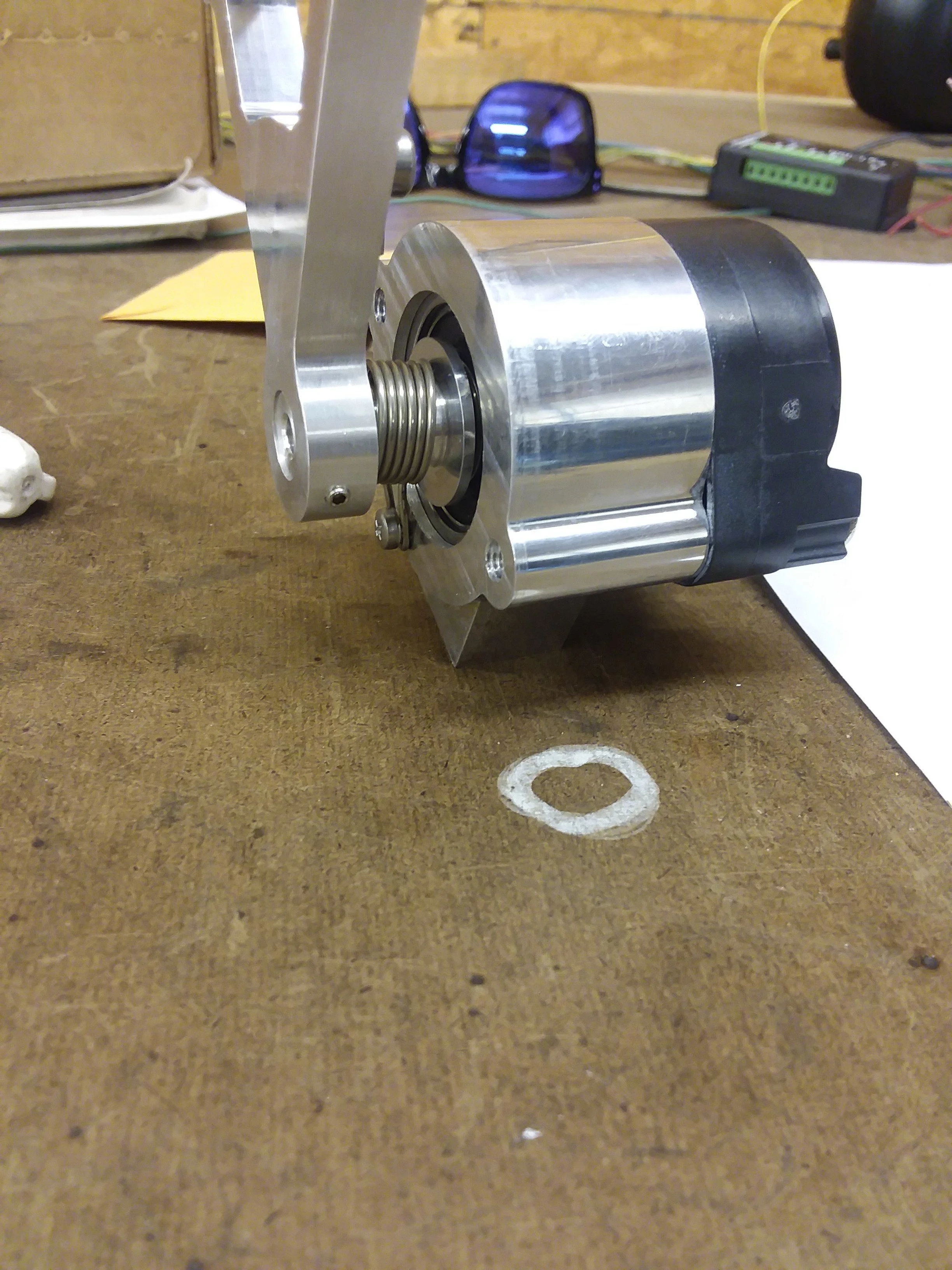
Here is an outboard stop with about 2000 pounds applied to it. My press guage is not accurate, the graduations are in tons, so I tried to get it to the first mark. Its a lot, you can see the the outboard stops really compress a lot, this has me worried.


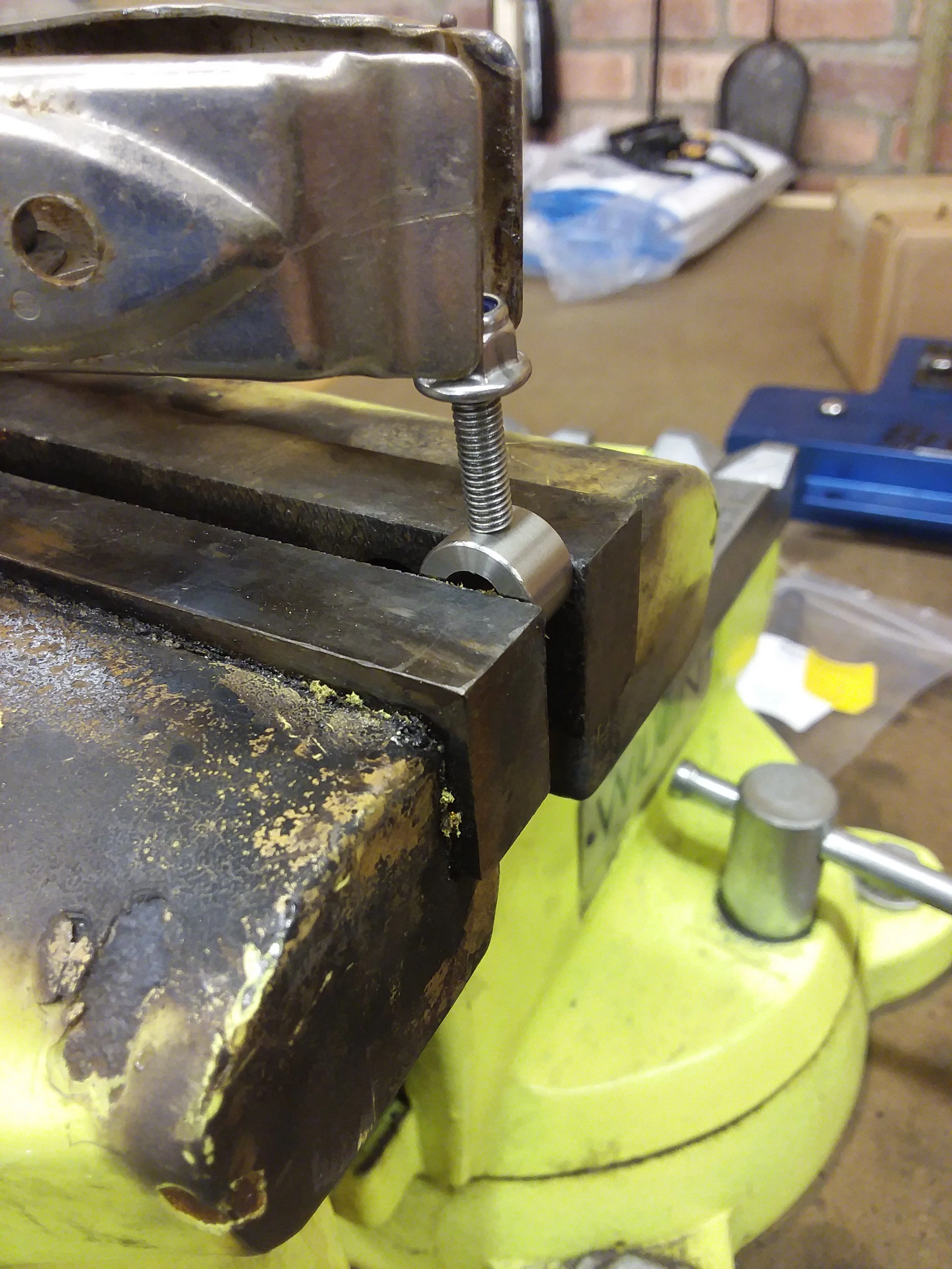
The inboard stops are much stiffer...


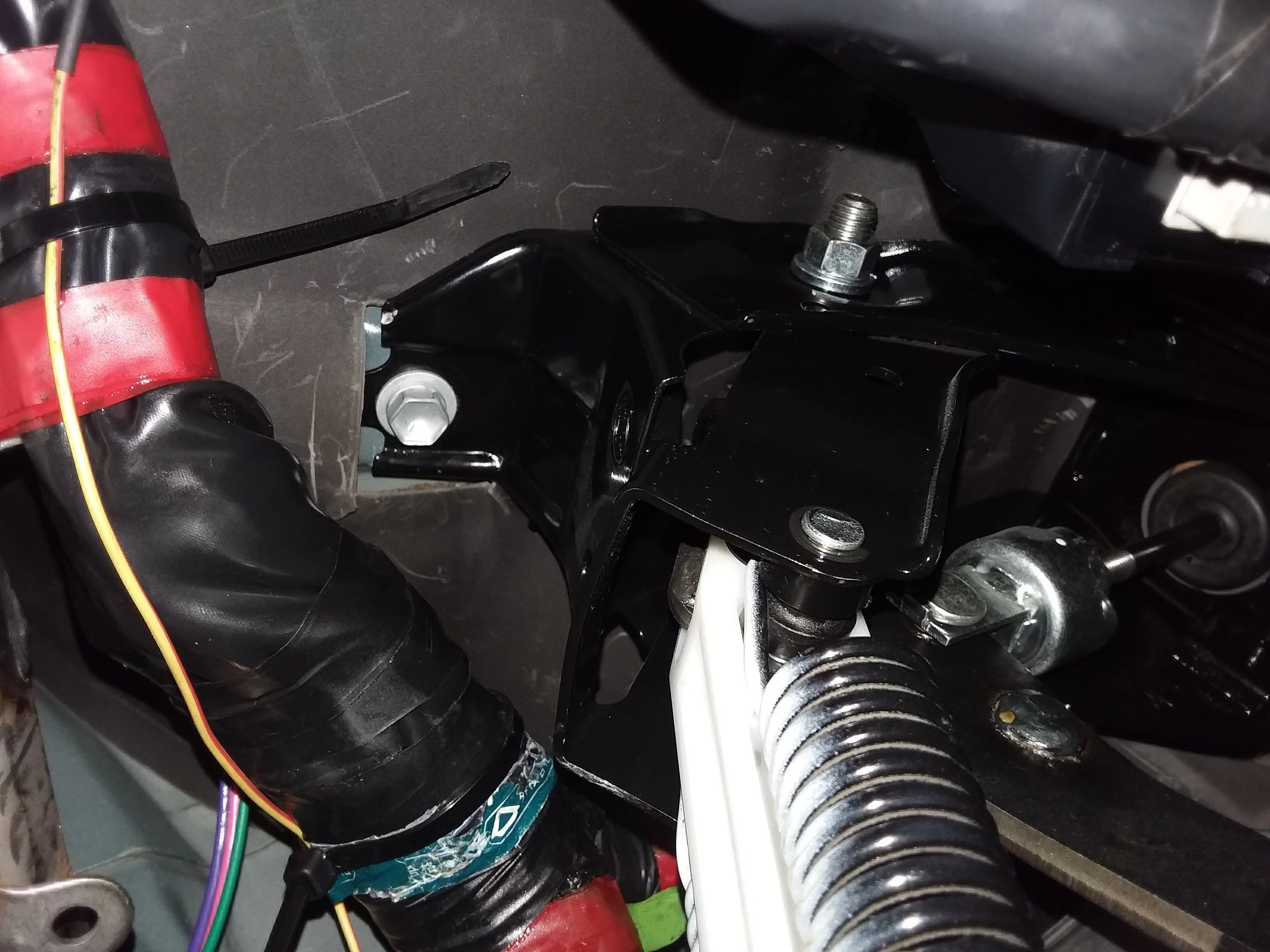
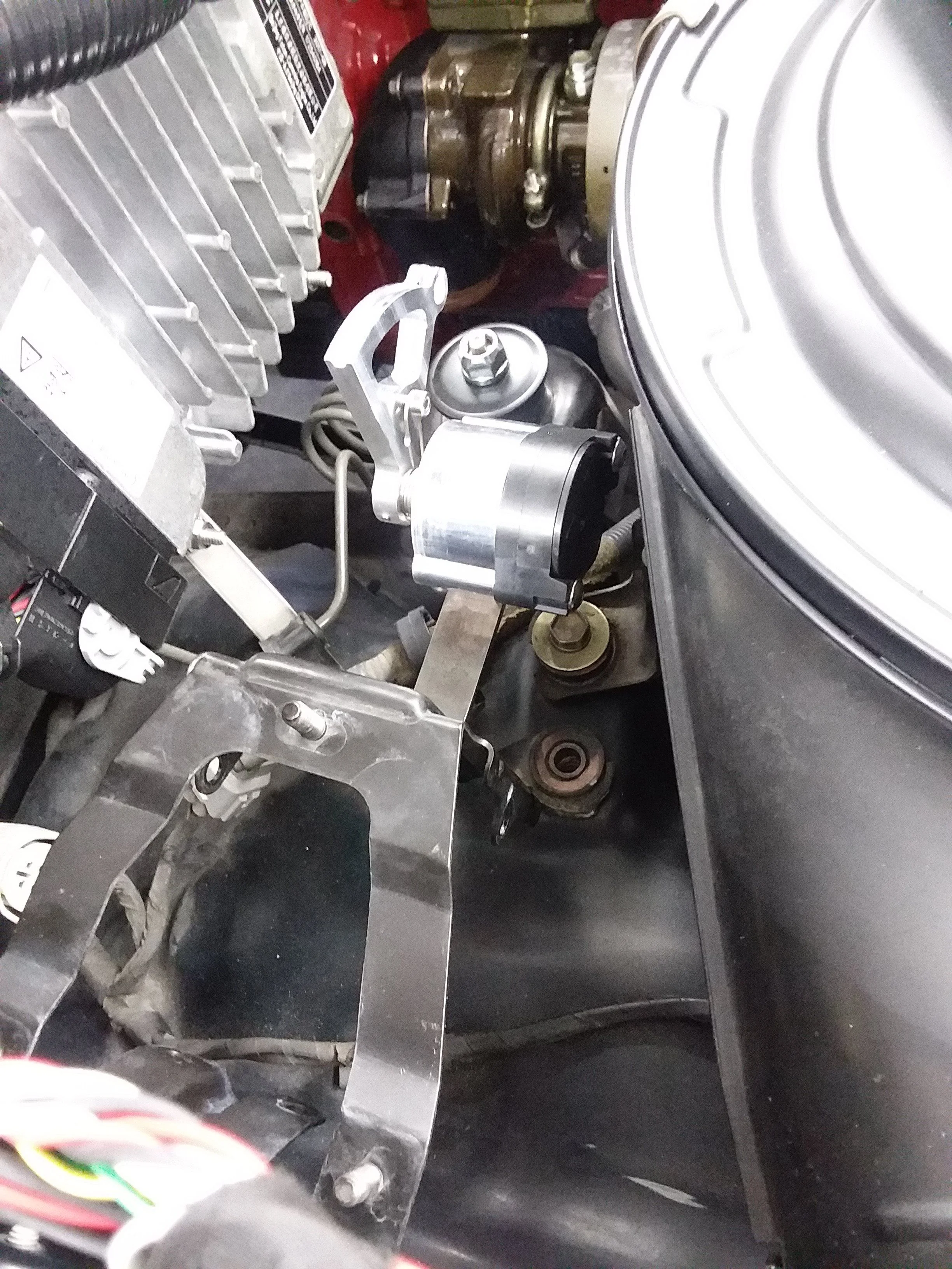
In a previous post I made the observation that the inboard RHS stop has about 1/2 inch of gap when the axle is touching both outer stops, meaning that my axle could possibly fit the oilpan if the right conditions were present. I think I am going to install 1 inch spacers over all of the bumpstops just to be sure that no contact occurs, and 1.5 inch spacer will be installed in the inboard RHS stop to make it the same as the LH one. Does anyone think this will cause any problems?
Cool info about the bump stops... I'd imagine the inboard stops are OEM. You could google the part number on them, but I'd assume you'll find they are Toyota parts.

As for the spacers on the bumps, I don't think you'll have any issues as long as you still have sufficient up travel from ride height to not be hitting them all the time during normal driving. If you do have the up travel, it may also be worth spacing the primary (inside the coils) stops down further than the secondary ones so you get the softer, more progressive reaction from them before the firmer action of the frame mounted ones.
 
I don't suppose a mid or front sump pan would help out with the axle or steering clearance would it
 
Just screw a nut down over the stud and cut it off with a cutoff wheel or dremel and unthread the nut. No reason to make a special spacer dowel on the lathe. lol

It appears that the airbox itself is different for the 1FZ. That stud for the wing nut is way to long, another f***ing problem to solve. It just never ends on this damn thing! I guess i'll make a spacer dowel on a lathe, I dont feel like cutting the stud out.

And to cap things off, finally after months of waiting and hoping for a cheap one on ebay, it arrived. Now I can pretend to drive it and not scrap my hand on the threads.

Saludos!
 
Cool info about the bump stops... I'd imagine the inboard stops are OEM. You could google the part number on them, but I'd assume you'll find they are Toyota parts.

As for the spacers on the bumps, I don't think you'll have any issues as long as you still have sufficient up travel from ride height to not be hitting them all the time during normal driving. If you do have the up travel, it may also be worth spacing the primary (inside the coils) stops down further than the secondary ones so you get the softer, more progressive reaction from them before the firmer action of the frame mounted ones.

That's a good idea, I think I might just do that. I'll check my measurements again and come up with a reasonable offset amount.

I don't suppose a mid or front sump pan would help out with the axle or steering clearance would it

Not on an 80 series, it has to be behind the axle and set to the left just a bit. I think the 1FZ oil pan is not symmetric wrt the crank axis either, so I suppose I should have expected this to be a problem.

Just screw a nut down over the stud and cut it off with a cutoff wheel or dremel and unthread the nut. No reason to make a special spacer dowel on the lathe. lol

I'm not 16 anymore...
 
To each their own, I think a proper length stud would look a lot better than a stud 5" too long with a fancy spacer on it.


Agreed. I was hoping the stud could simply be removed, but it does not appear to be removable. I think I will end up welding on the airbox anyway, I think the PS reservoir will end up getting attached in the future. If that's the case I will swap out the stud.

The spacer would look goofy that's for sure, maybe I could engrave a pinup model on it to give it some flare.
 
The spacer would look goofy that's for sure, maybe I could engrave a pinup model on it to give it some flare.

The obvious answer...dancing hula girl.

file.png
 
Why not just run a tap down the air cleaner stud until you have enough thread, then cut off the excess? No removal of the stud required.
 
  • Like
Reactions: ppc
A small update finally. Been super busy as of late so not much progress on the cruiser project.
Two things have gotten done since the last update, the new remote throttle assembly is done, and the pedal to CC actuator cable is secured.

I secured it in two places using some nice vibration isolating p clamps with stainless bands from McMaster. I had to make some mounting points, so little stainless M5 bolts got welded to various things. Gotta give a shoutout to weldporn pink tungsten, I use it for stainless, steel and aluminum. The stuff holds a nice point!


For the remote throttle, still need a mounting location and a nice cable made. Will get to that one of these days. Took me awhile to find an acceptable torsion spring, but in the end McMaster had it for like 3 bucks, and its even stainless so it should not rust. The bearing is also stainless and sealed from the elements, should last a long time. I'll let the pics do the rest of the talking....


Anyone on here make custom throttle cables?
 
Had a couple more free hours and tried to bang out a few more things on my to-do list.
Needed to wire in the Diesel Tach Converter Box, tried to wire it in the best way I could.

I used a metra-pack 180 series 4 terminal connector to allow for future repair...


I have tried to document the wiring of this part. It seems to me that the output from the converter box needs to go to pin 4 on I2.


Next I tried to figure out a way to mount the throttle sensor close to the CC actuator. I modified the CC actuator bracket a little...


Here is a mock up showing clearance to the airbox. I hope I can get a cable that will work for this...


We will see if this works... :)
 
Cool info about the bump stops... I'd imagine the inboard stops are OEM. You could google the part number on them, but I'd assume you'll find they are Toyota parts.

As for the spacers on the bumps, I don't think you'll have any issues as long as you still have sufficient up travel from ride height to not be hitting them all the time during normal driving. If you do have the up travel, it may also be worth spacing the primary (inside the coils) stops down further than the secondary ones so you get the softer, more progressive reaction from them before the firmer action of the frame mounted ones.


I hope you build a skid plate for that oil pan, I just found a nice ding in my inter cooler tube and oil pan you would have been 11 quarts low after that o_O
 
I guess you were doing to hard off roading?

I don't think there is much room down there for skid plates. It will be about as protected as the stock 1fz engine.
It might be in the cards to move the knuckle connector shaft to in front of the axle housing. I have over an inch of clearance between that rod and the oil pan, I don't think there will be any problems.

I should have the new oil pan done and installed in a few weeks, i'm too busy at the moment to work on it.
 
I found a mistake in my wiring that needs to be fixed, :(
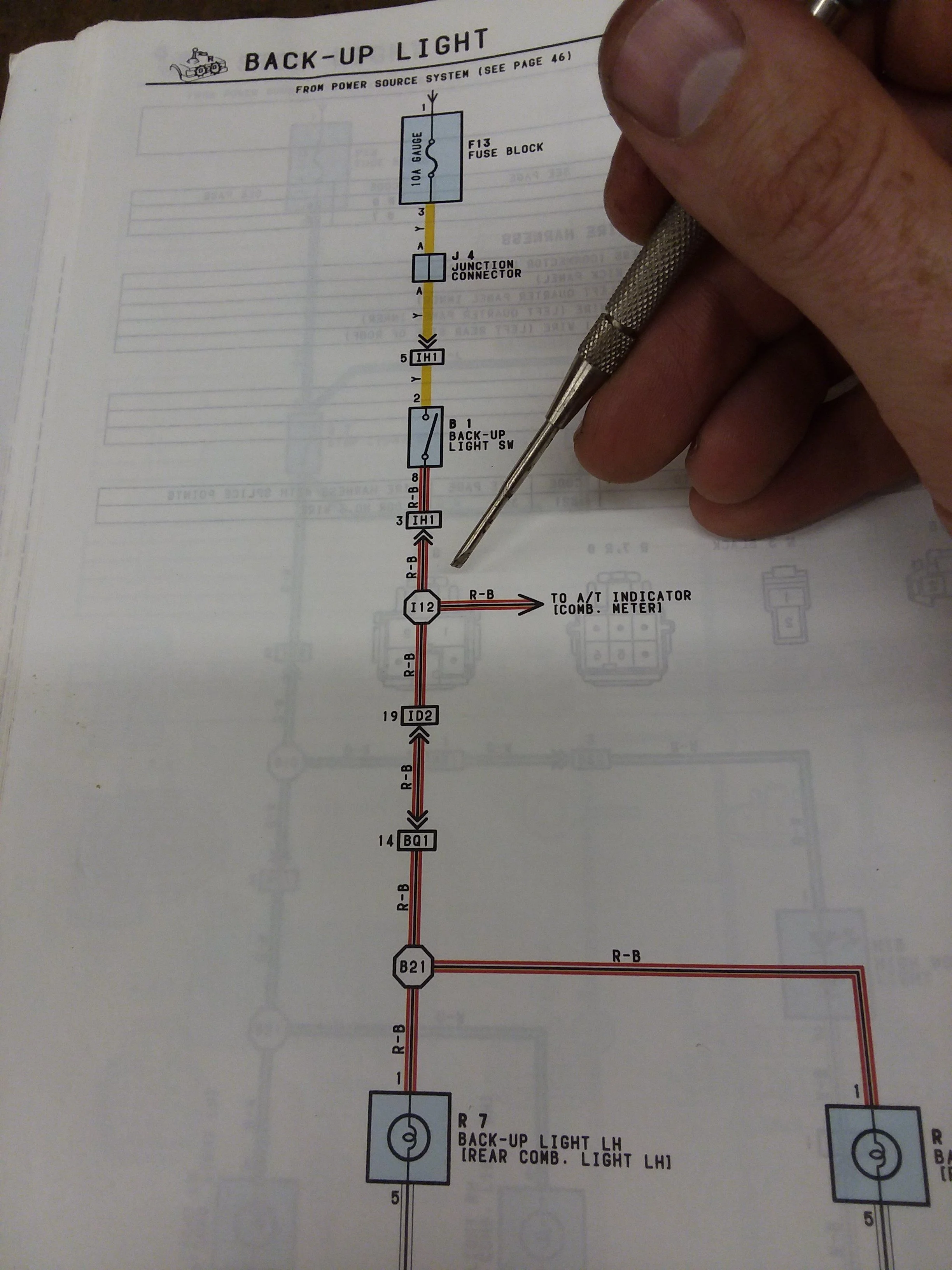
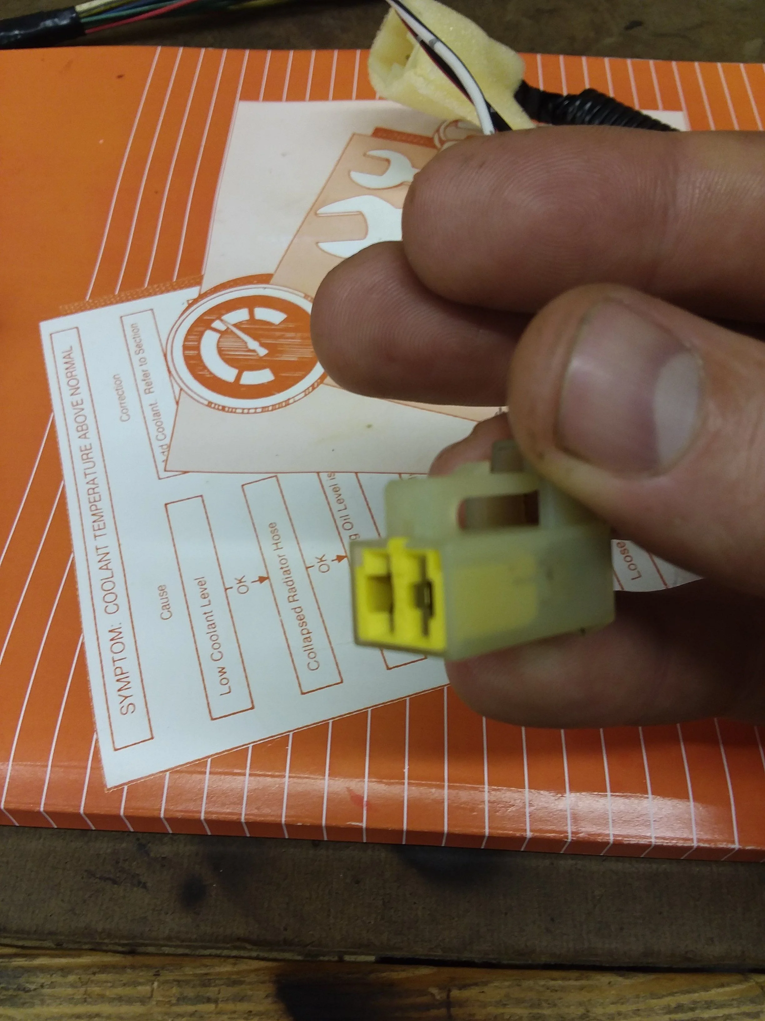
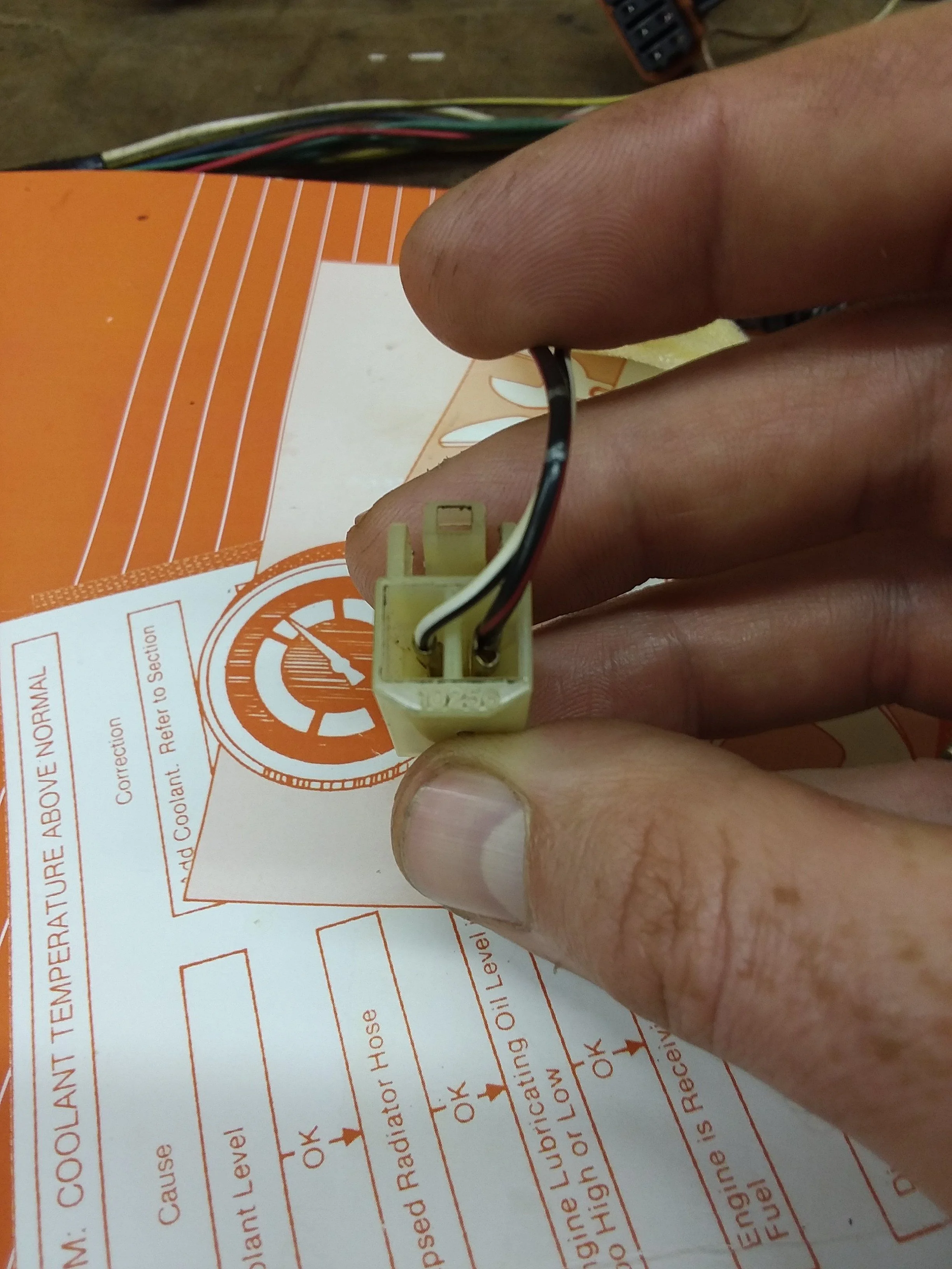
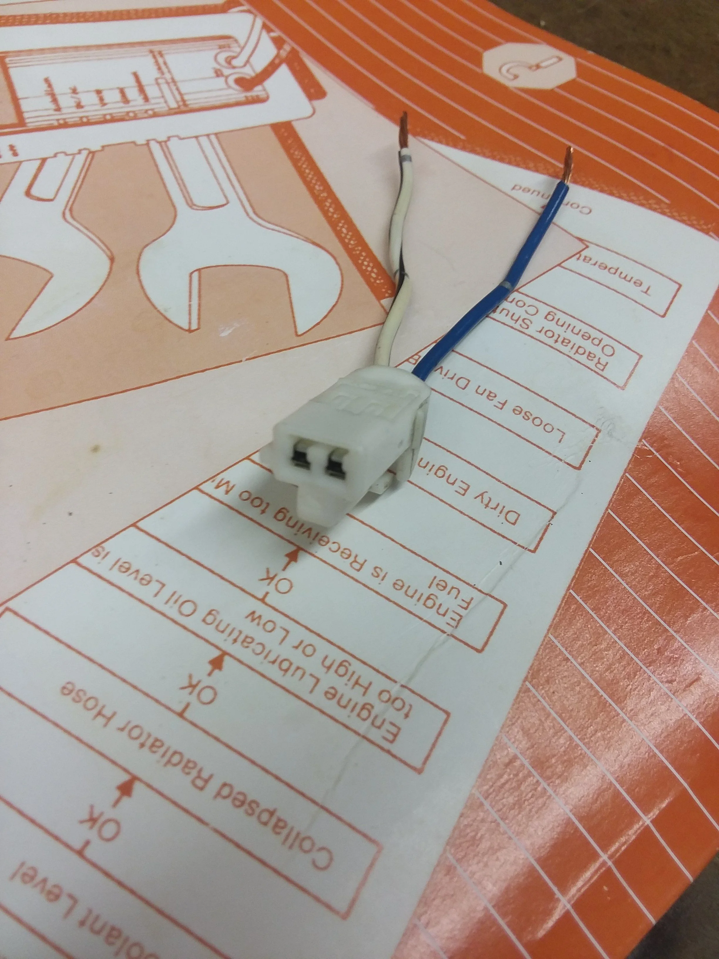
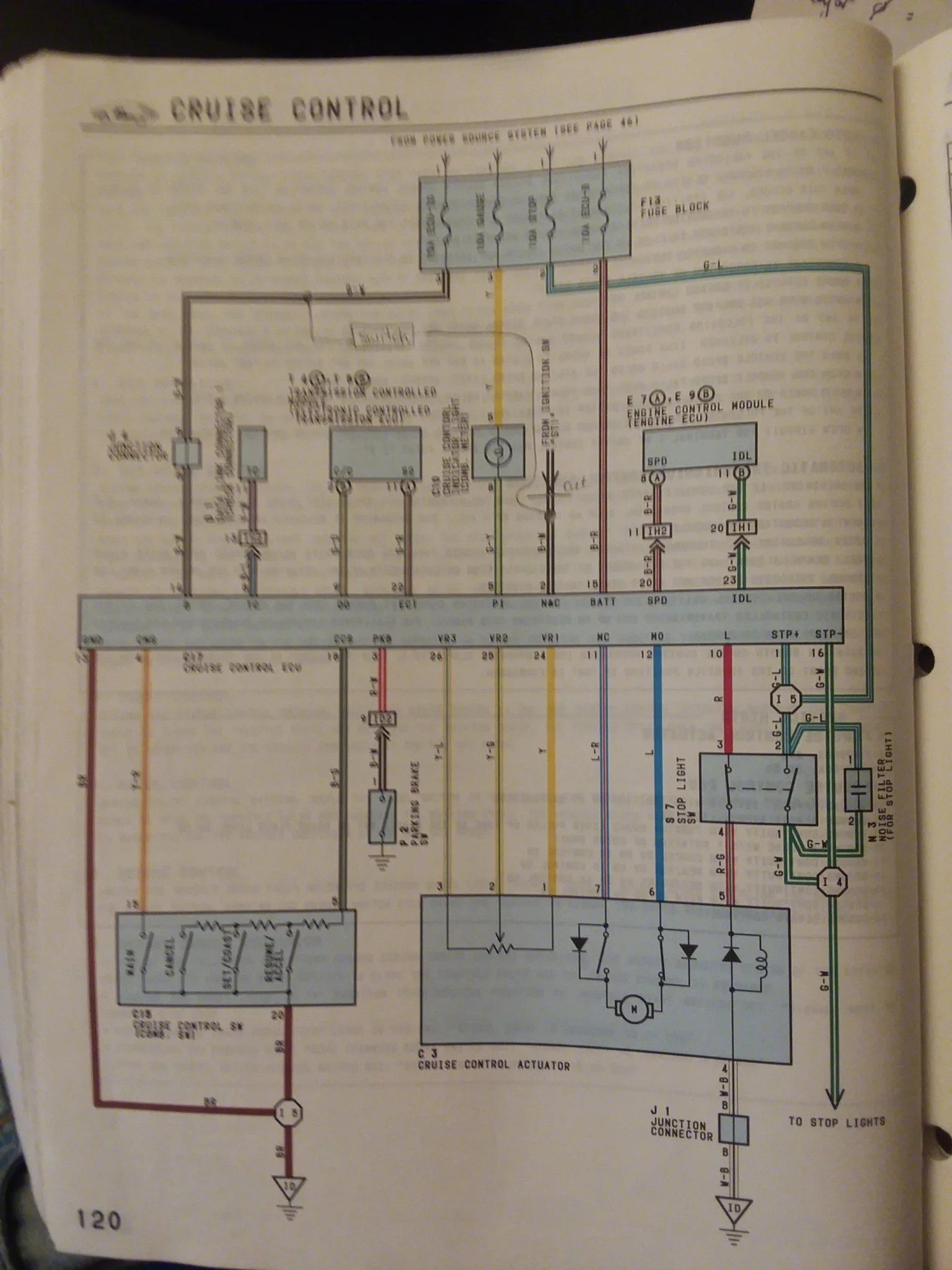
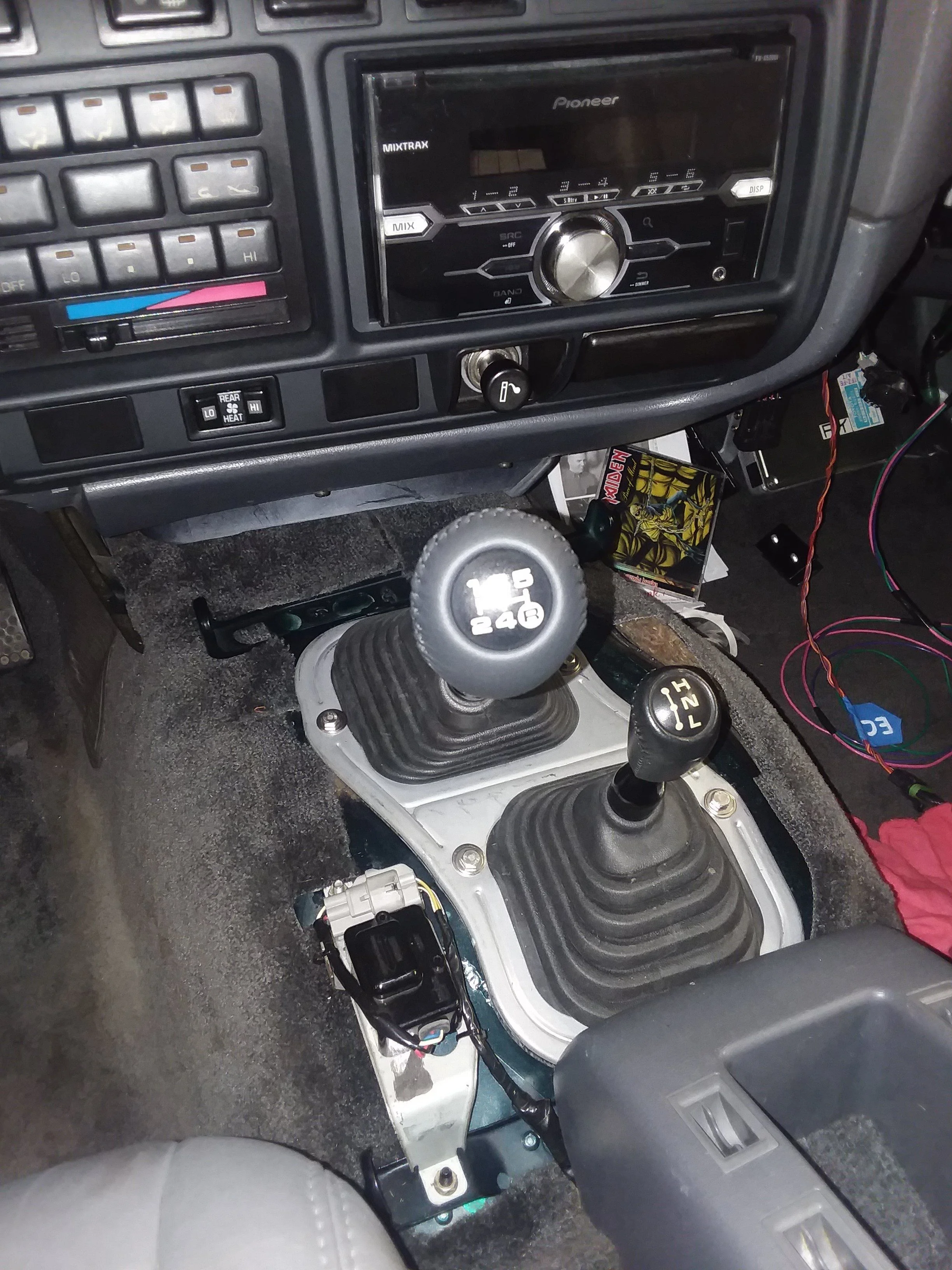
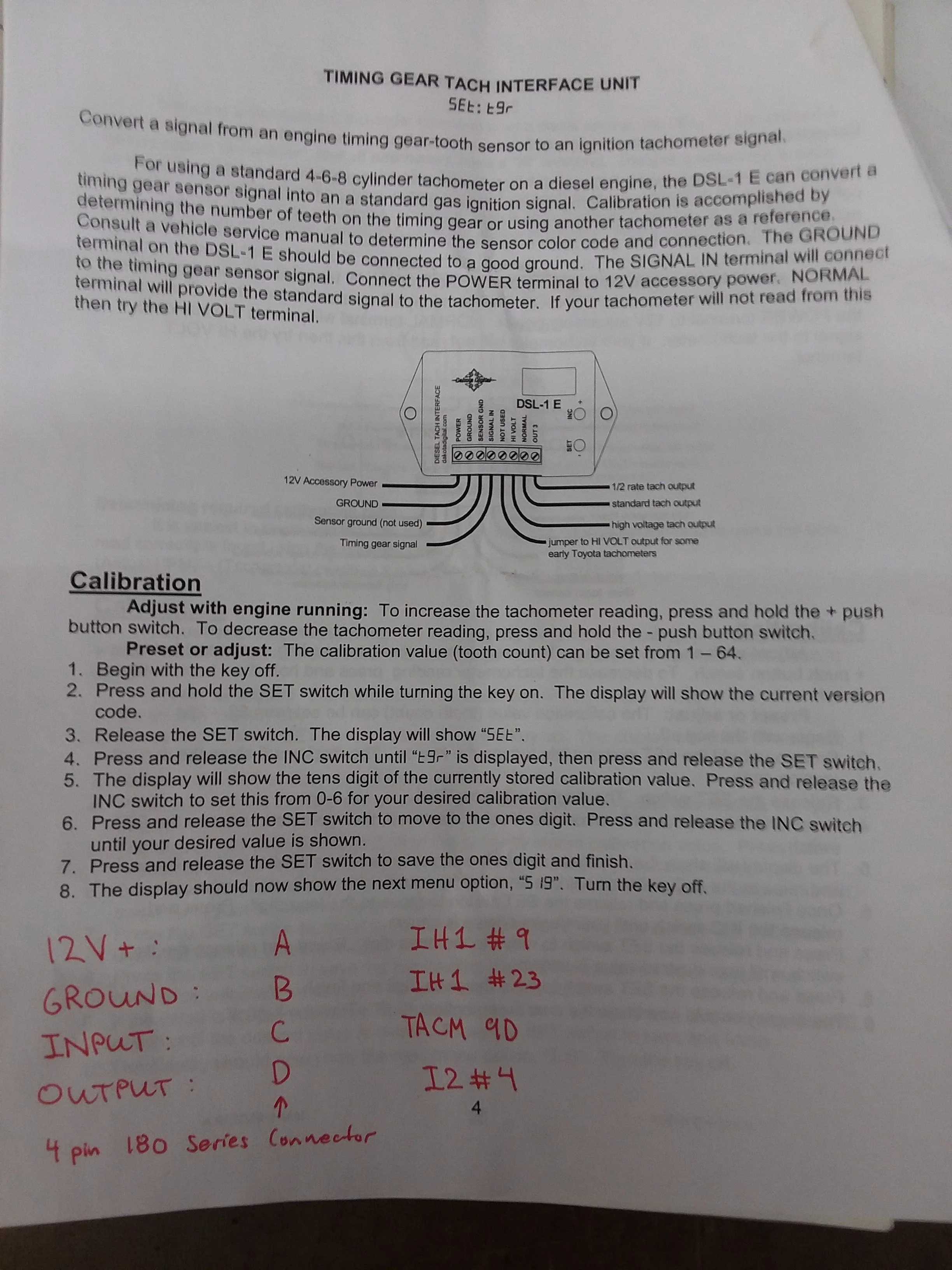
. It goes all the way back to post 37 where I was talking about the reverse light wiring. I neglected to realize that the R in the PRNDL display and the actual backup lights are on the same circuit, in its current configuration when the Cummins ECM throws a code it will light up the reverse lights, no what we want.

To fix properly the dash needs to be removed, but that is only going to happen if I find a mint, and I do mean mind condition dash. The 80 series dash is a PITA to remove, and my definition of mint does not jive with people on mud who are parting out cruisers, so its not going to happen.

There is a splice in the cowl harness that should have been cut and connector to AT fluid temp sensor wire inside the IH1 plug behind the glove box.


Recall that the AT fluid temp sensor wire was repurposed from the A442F harness that I converted to H151 spec, so when the H151 is in reverse it should complete a circuit thru the back up light switch thus lighting the lights.

My work around for this required two splice jobs, starting at the female side of IH1 plug that is connected to the cowl harness. Taking the AT temp wire, I believe its pin 7, pictured here.


It needs to be connected to the wire in the left kick panel (for LHD I imagine) that actually triggers the reverse lights. This should be pin 19 I think...


Here in the factory configuration you can see all the involved connectors and splice joints. Pin 19 of ID2 is where you put current to light your lights. Also you see here the I12 splice joint, a lot going on here.


These little details add lots of time to a project like this.
 
Found a clutch switch that will work. I had the original 80 series one but could not find a connector that would work. Got a sensor off of rock auto for a 1994 4runner since I have a junked one in my yard to get the corresponding connector from. The idea is to use this switch to turn off the cruise control when the clutch is pressed in to avoid having the engine sit at 100% throttle. I think this will work by grounding the pin that corresponds to the neutral safety switch on the cruise control computer. Time will tell if I am correct.

80 series switch on left and 4runner on the right.

The connector pig tail from the 4runner

The toyota part number can be found from this number

Here is where it goes. Sure is nice having that massive wiring harness right behind the spot where the sensor threads into the pedal bracket.
 
Seems that I spoke too early on this one. That 4runner switch does not work as intended. There are two different part numbers for 80 series clutch pedal switches, one has a white tip and the other is black. I did not think much of that difference 6 months ago, but today it became apparent.

The black one is normally open (with it installed and clutch pedal out), the white one is the opposite. For this application the black one seems to be the one for the job. If I am understanding the wiring diagrams correctly we need to apply 12 volts to pin 2 (N and C) of the cruise control computer when the clutch pedal is pressed in. This is like putting your AT into park or neutral which will kill the set cruise speed.

Here are the two switches for reference...

Also, I found the correct connector in my parts 4runner, I just had to look a little harder, it is in the left kick panal area.

I think this is the correct part number but its very possible that I have already interchanged them, I cant keep all this stuff straight

To break up the monotony of land cruisers, perhaps someone will chime in and tell me where these pictures were taken? Defintally an interesting part of america, lots of good train watching!!


I hope you all enjoyed your weekend!
 
Had a couple more free hours and tried to bang out a few more things on my to-do list.
Needed to wire in the Diesel Tach Converter Box, tried to wire it in the best way I could.

I used a metra-pack 180 series 4 terminal connector to allow for future repair...


I have tried to document the wiring of this part. It seems to me that the output from the converter box needs to go to pin 4 on I2.


Next I tried to figure out a way to mount the throttle sensor close to the CC actuator. I modified the CC actuator bracket a little...


Here is a mock up showing clearance to the airbox. I hope I can get a cable that will work for this...


We will see if this works... :)
That's the throttle sensor for the whole engine? Or does the cruise control have a separate throttle sensor?
 
Just one sensor for the engine. Engine came with a cab mounted foot tps, i am trying to convert it to a remote sensor so the oem cruise control stuff will work.
 
Got cruise cancel switch done I think, finally. Of Couse until I verify this works as planned don't trust me.

Need to get 12 volts thru clutch switch when pedal depressed, we do this with all in the cruise control computer connector.

Finished product.
 
Nobody wants to take a stab at those train pictures?
 

Users who are viewing this thread

Back
Top Bottom