- Thread starter
- #221
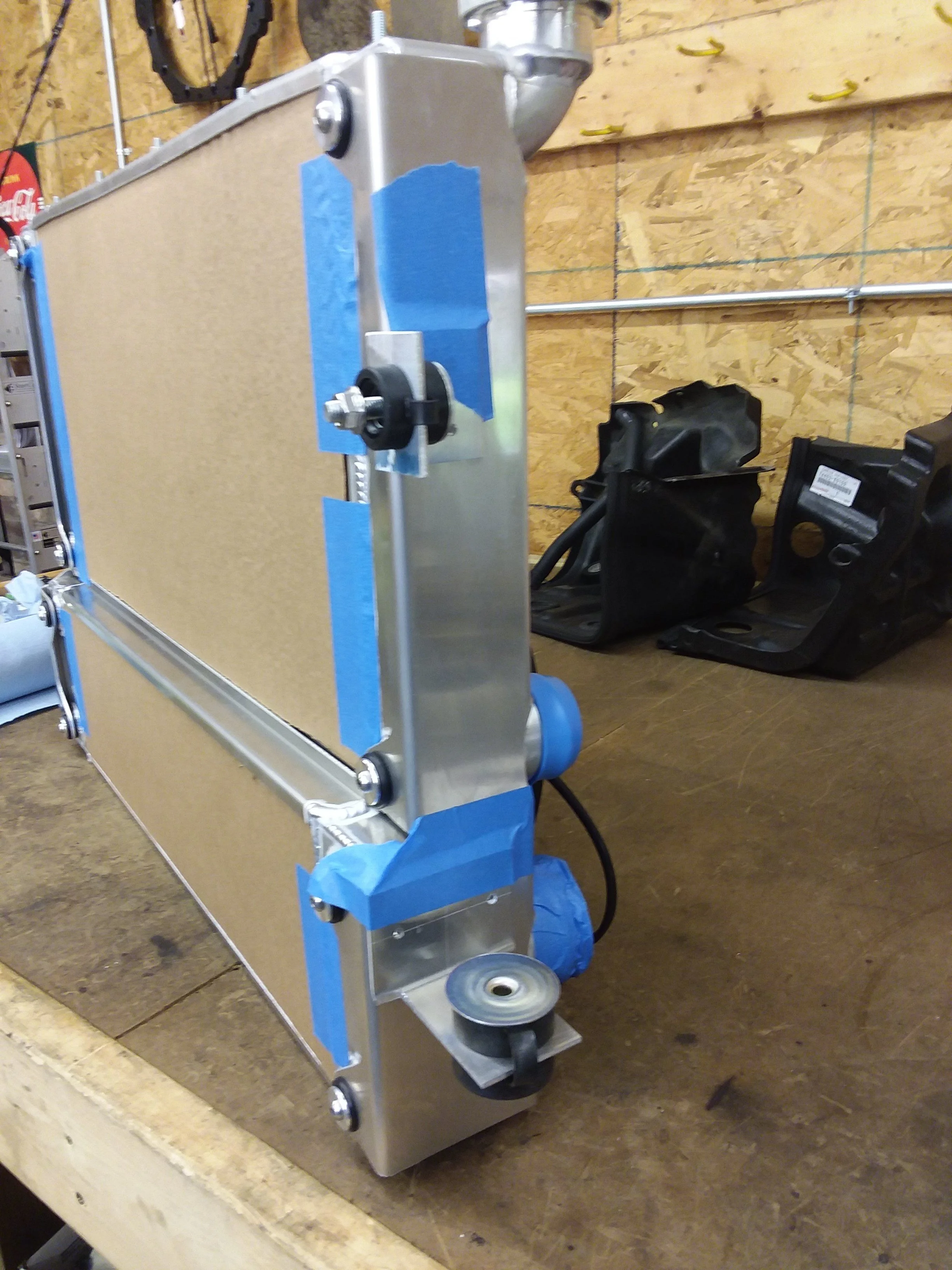
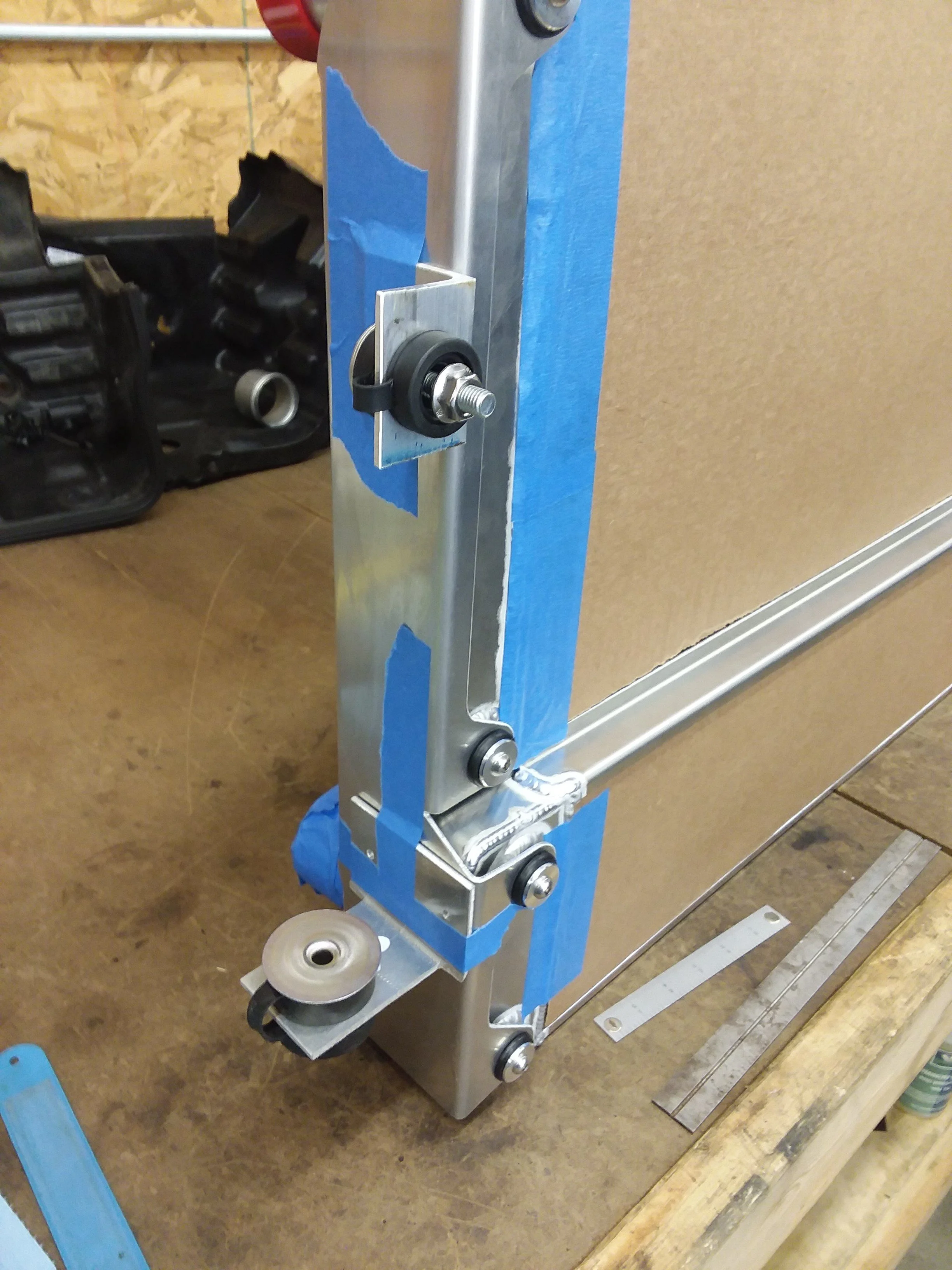
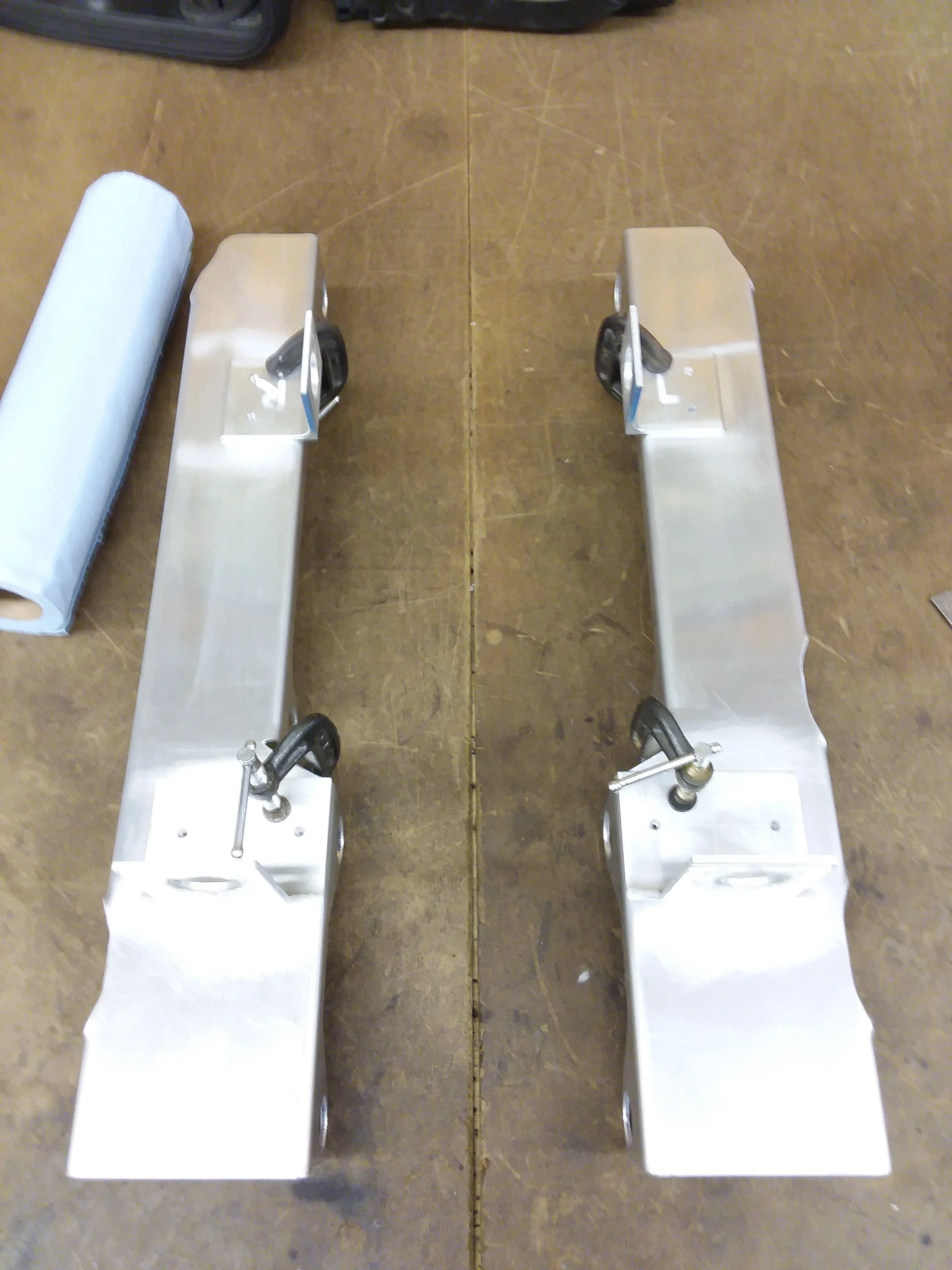
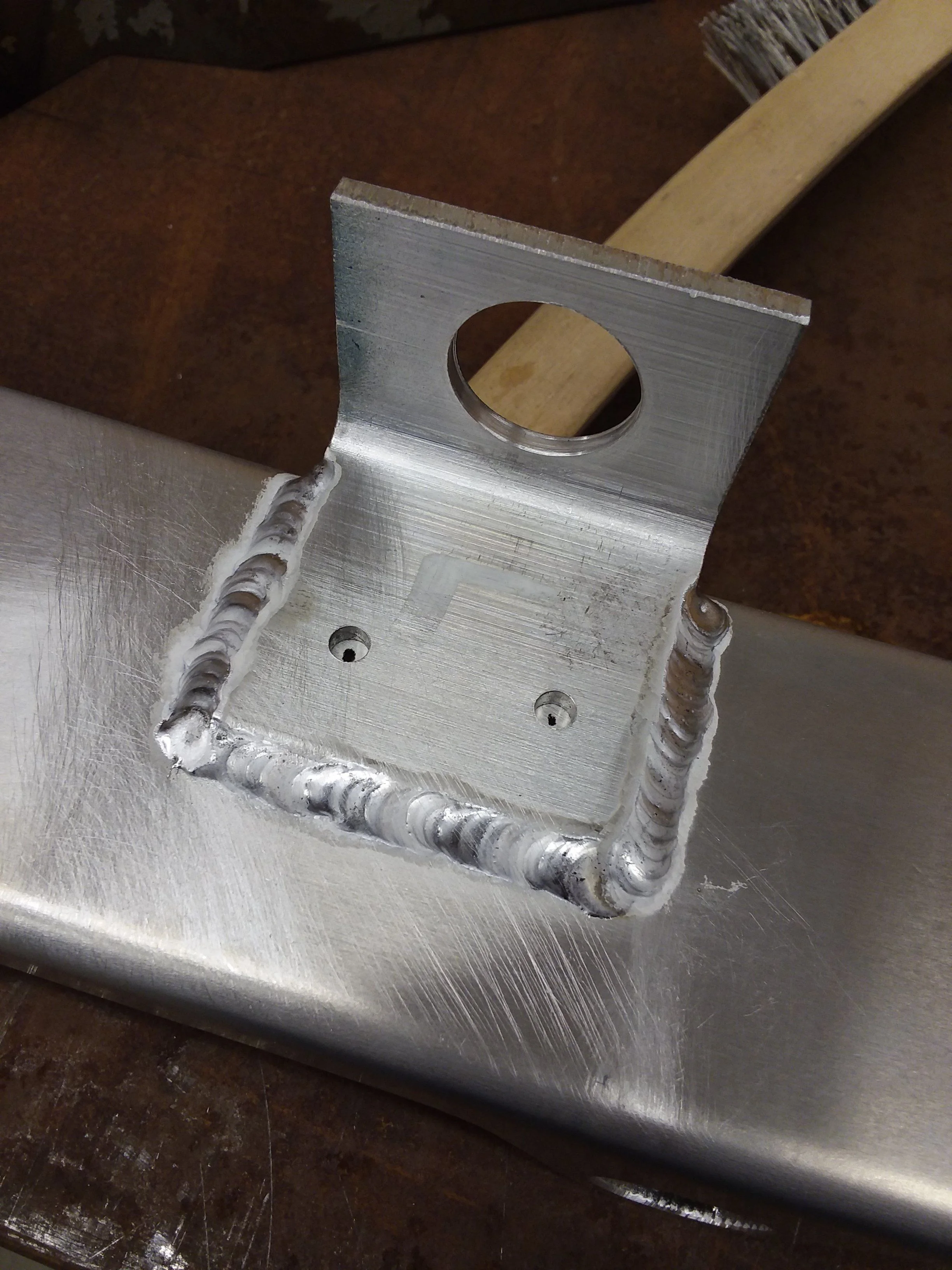
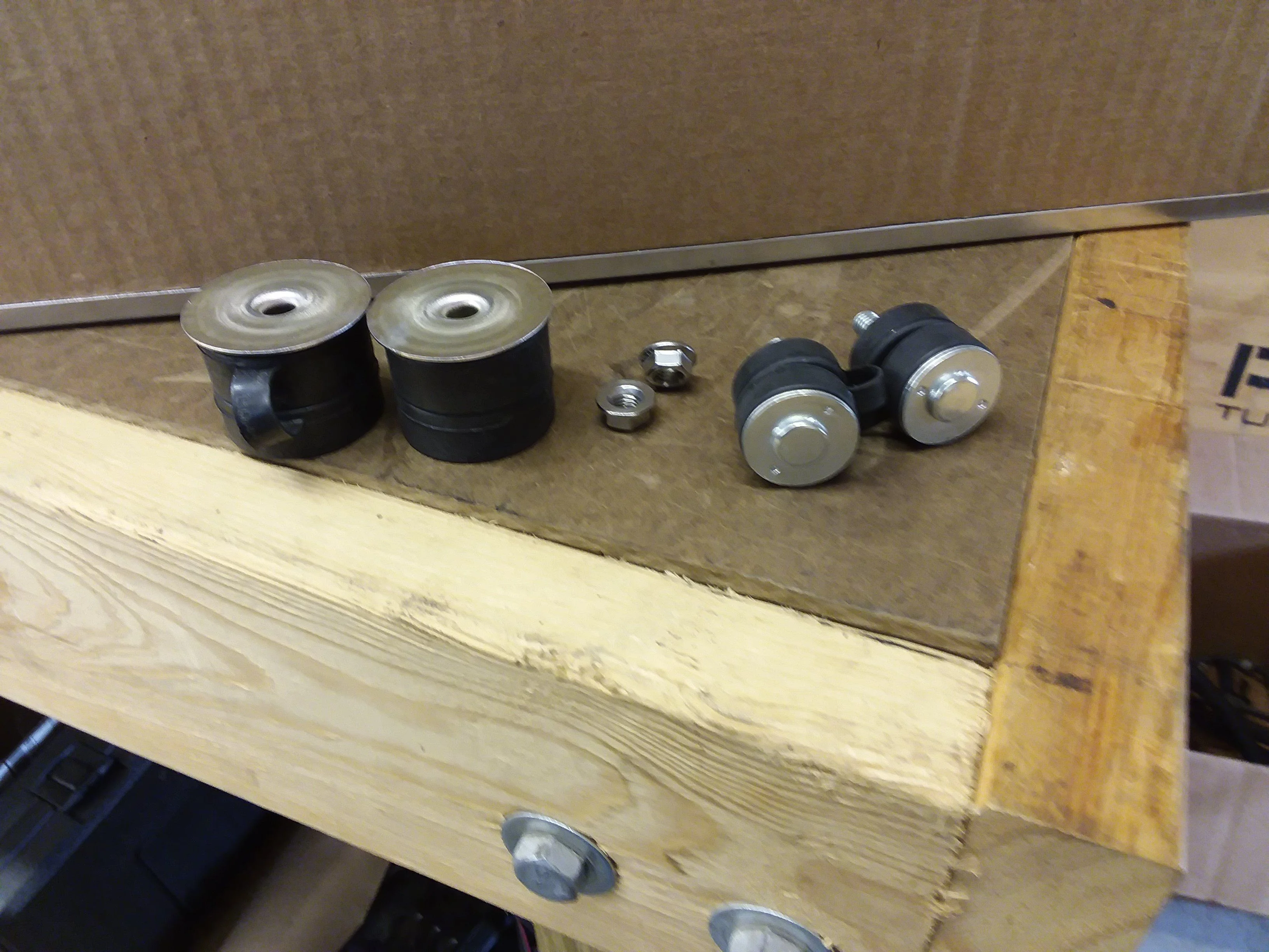
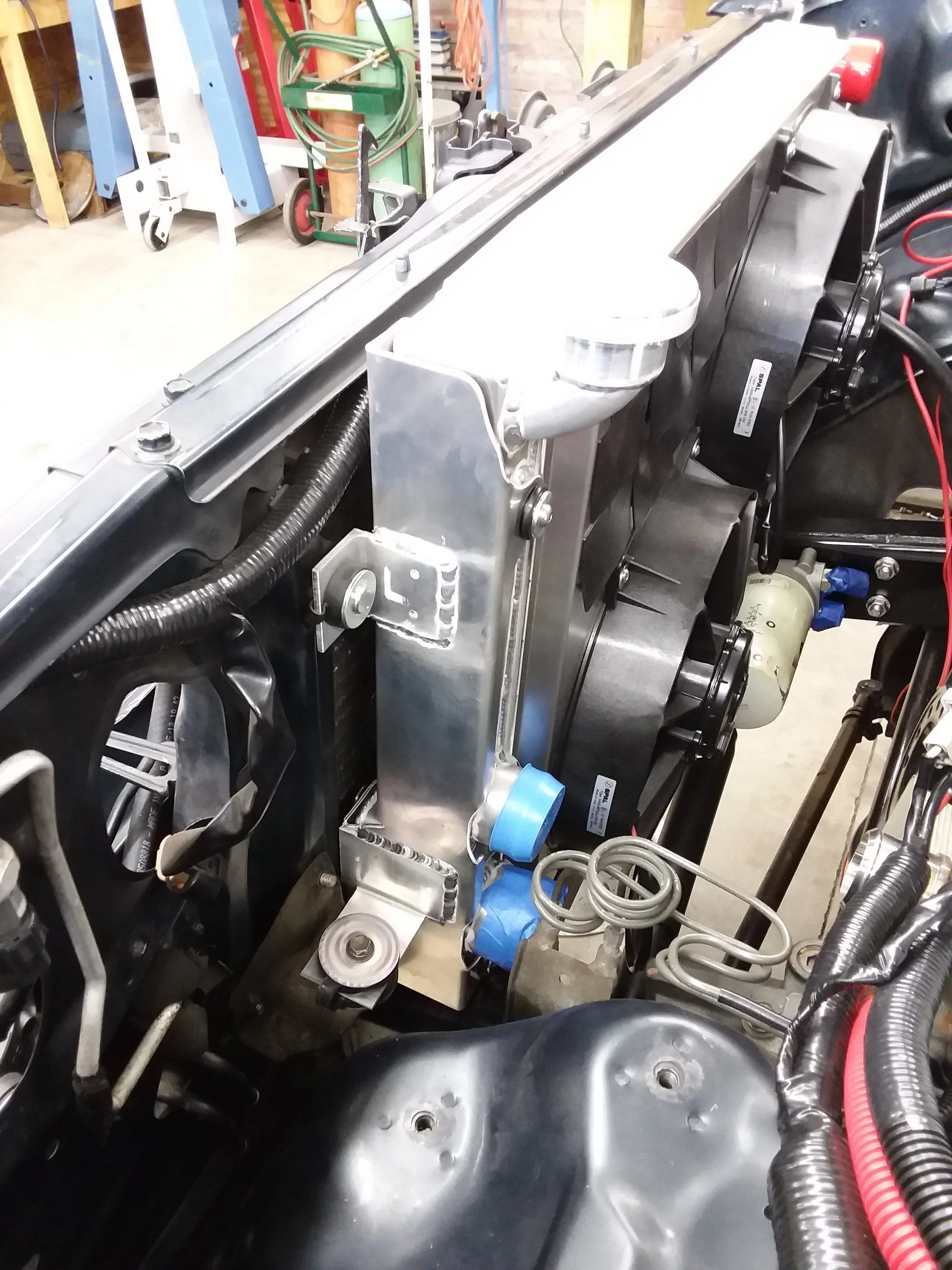
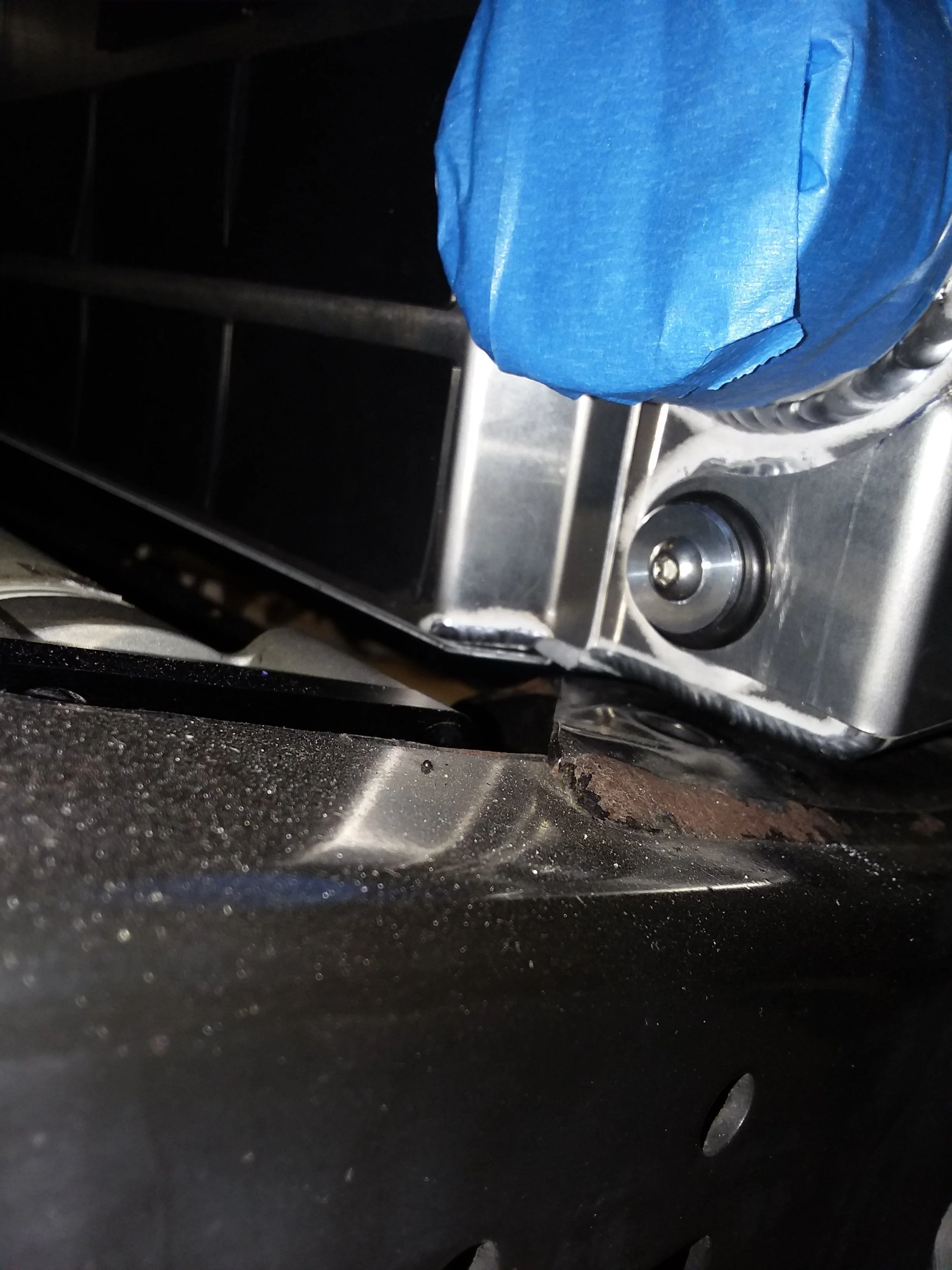
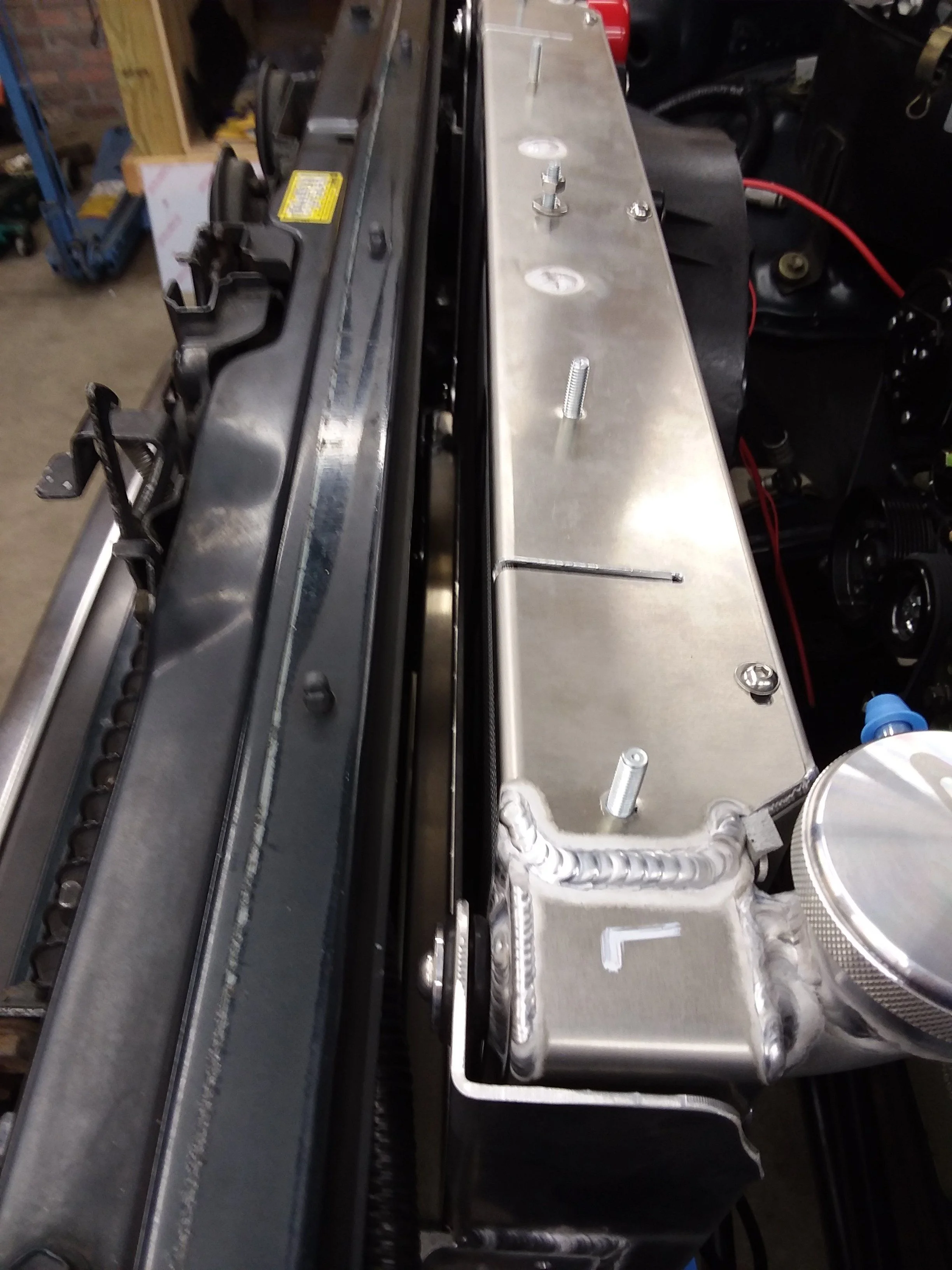
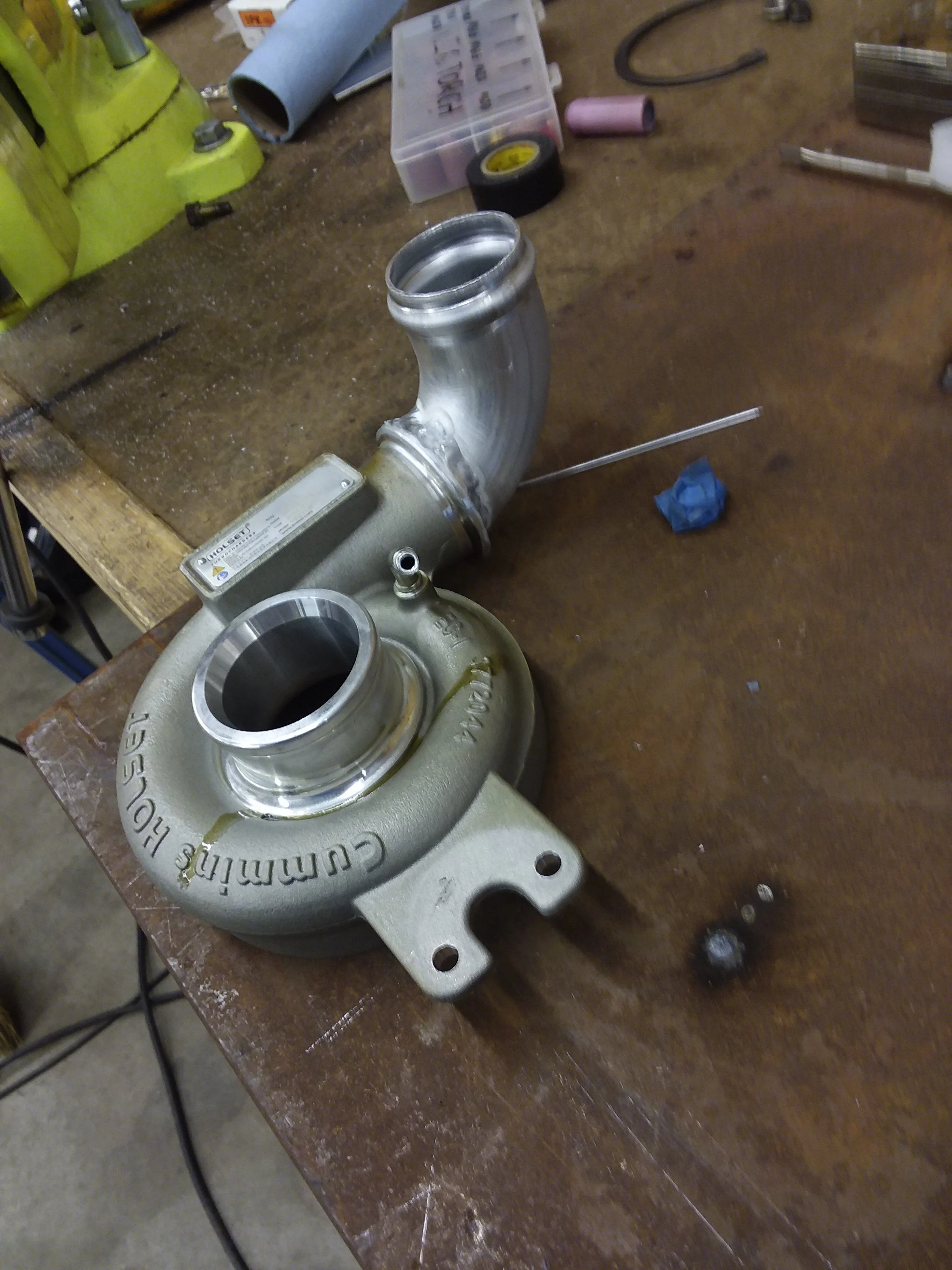
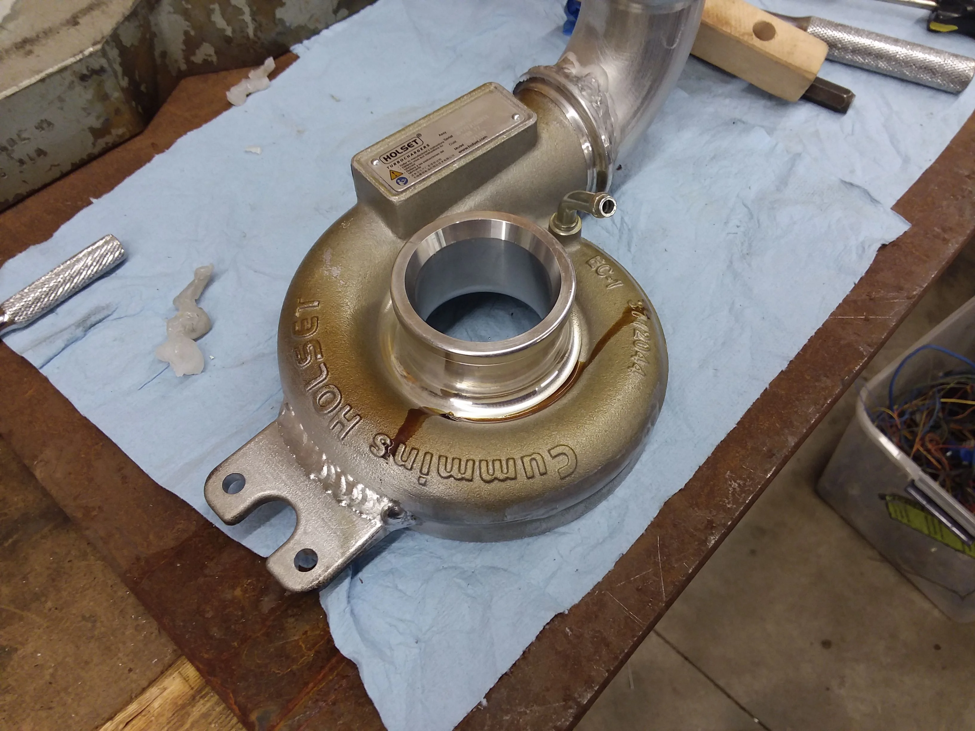
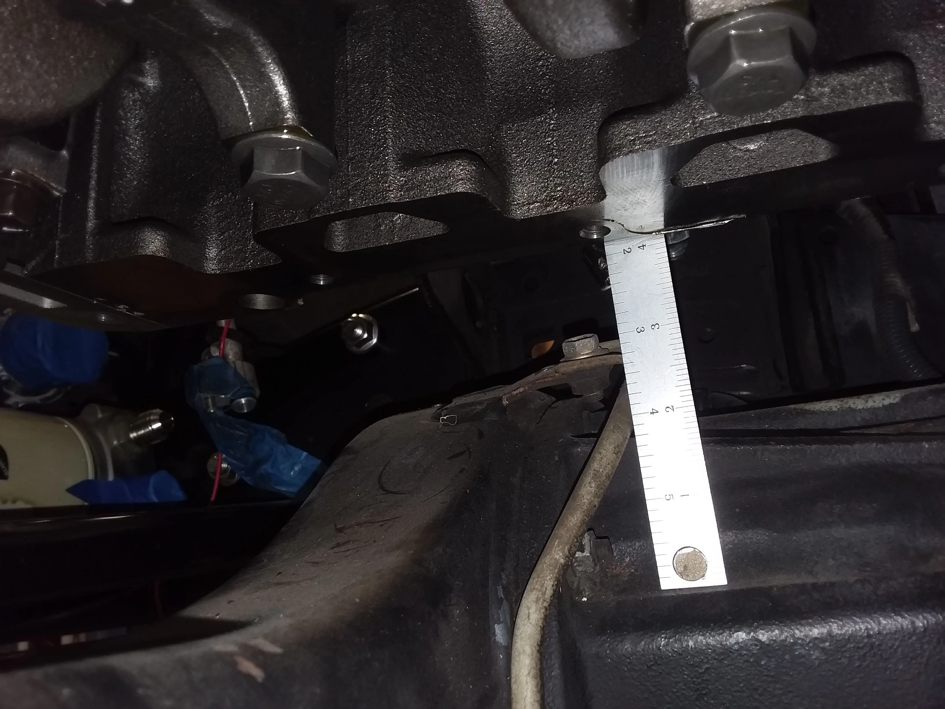
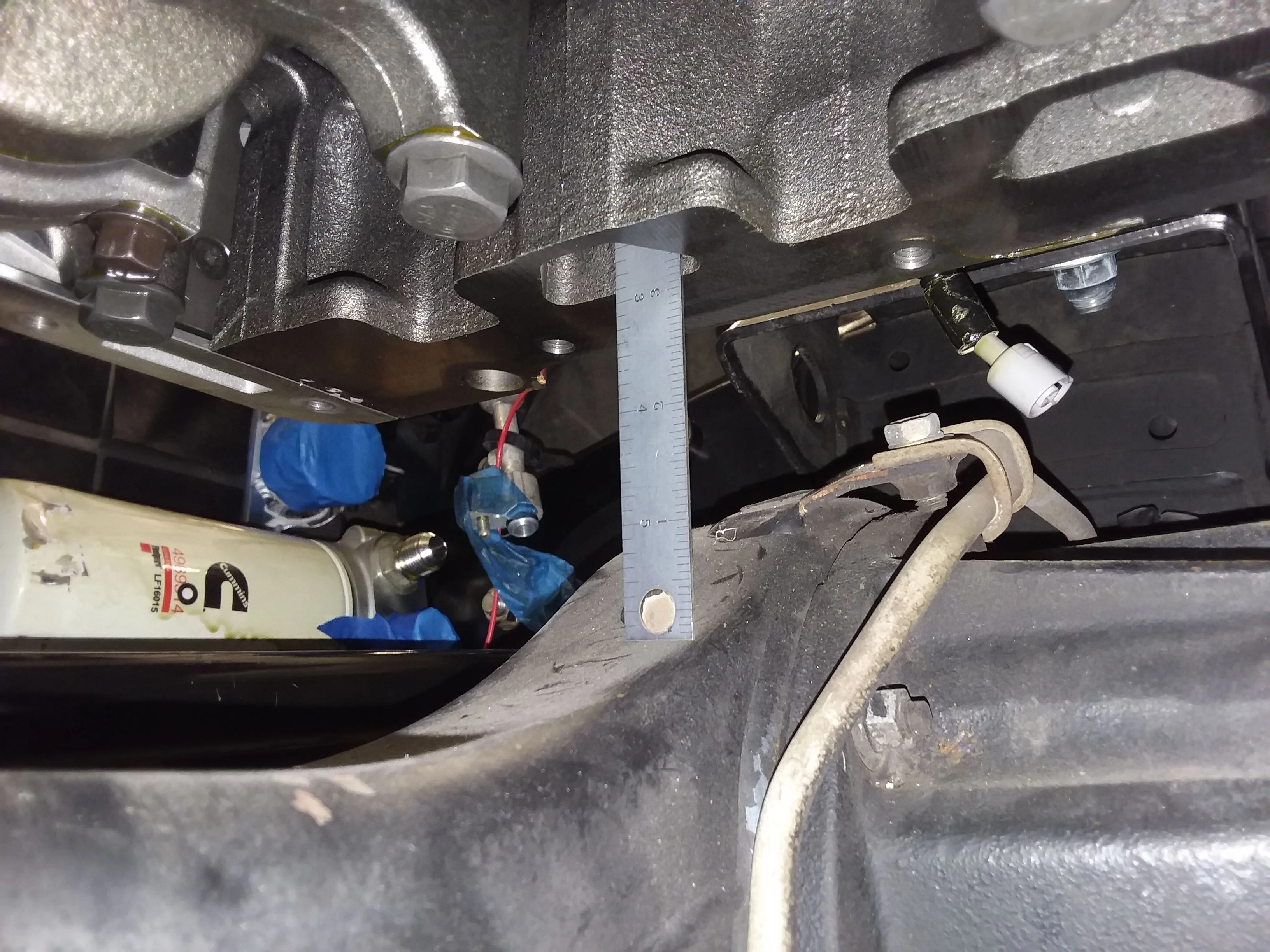
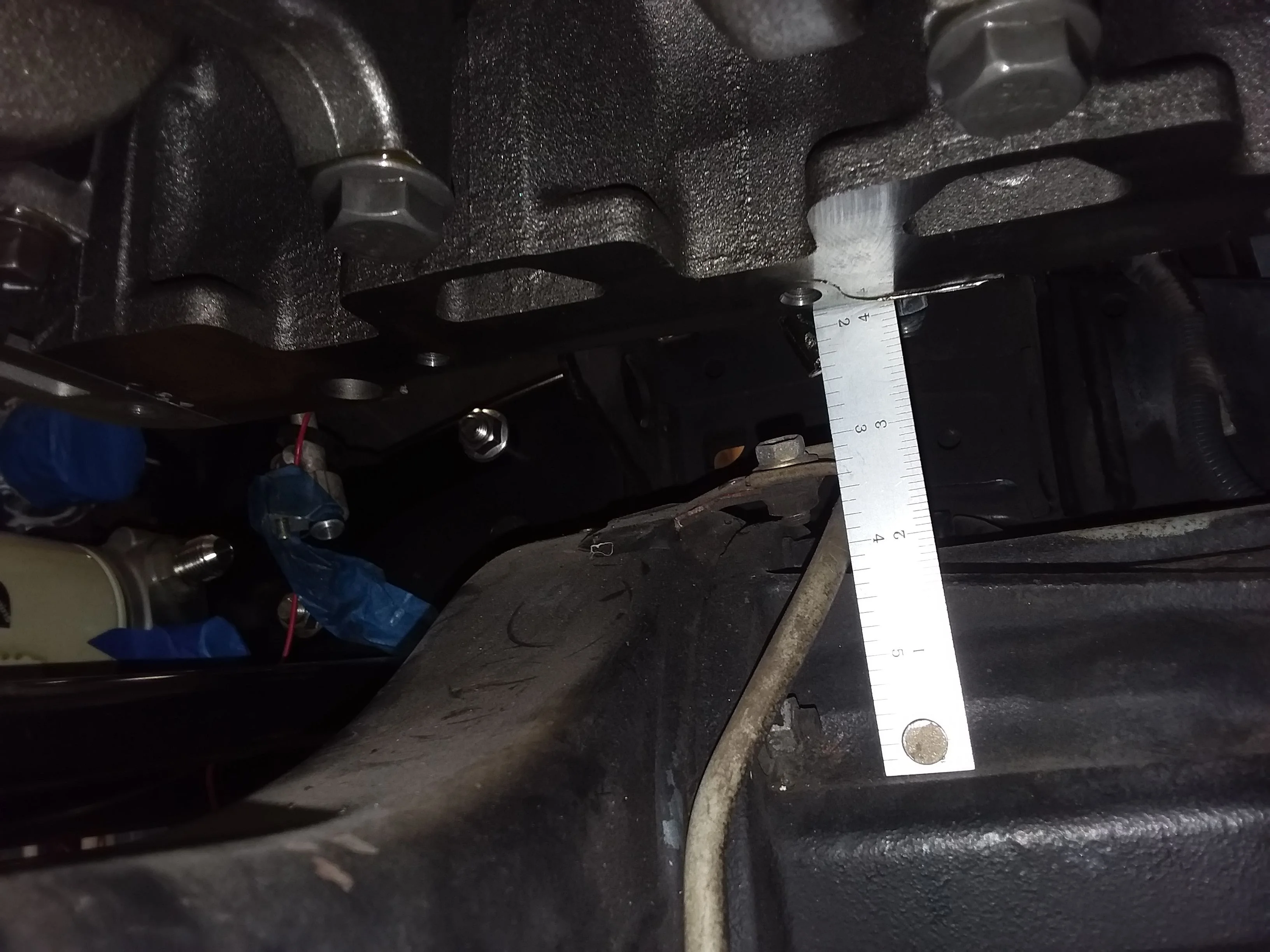
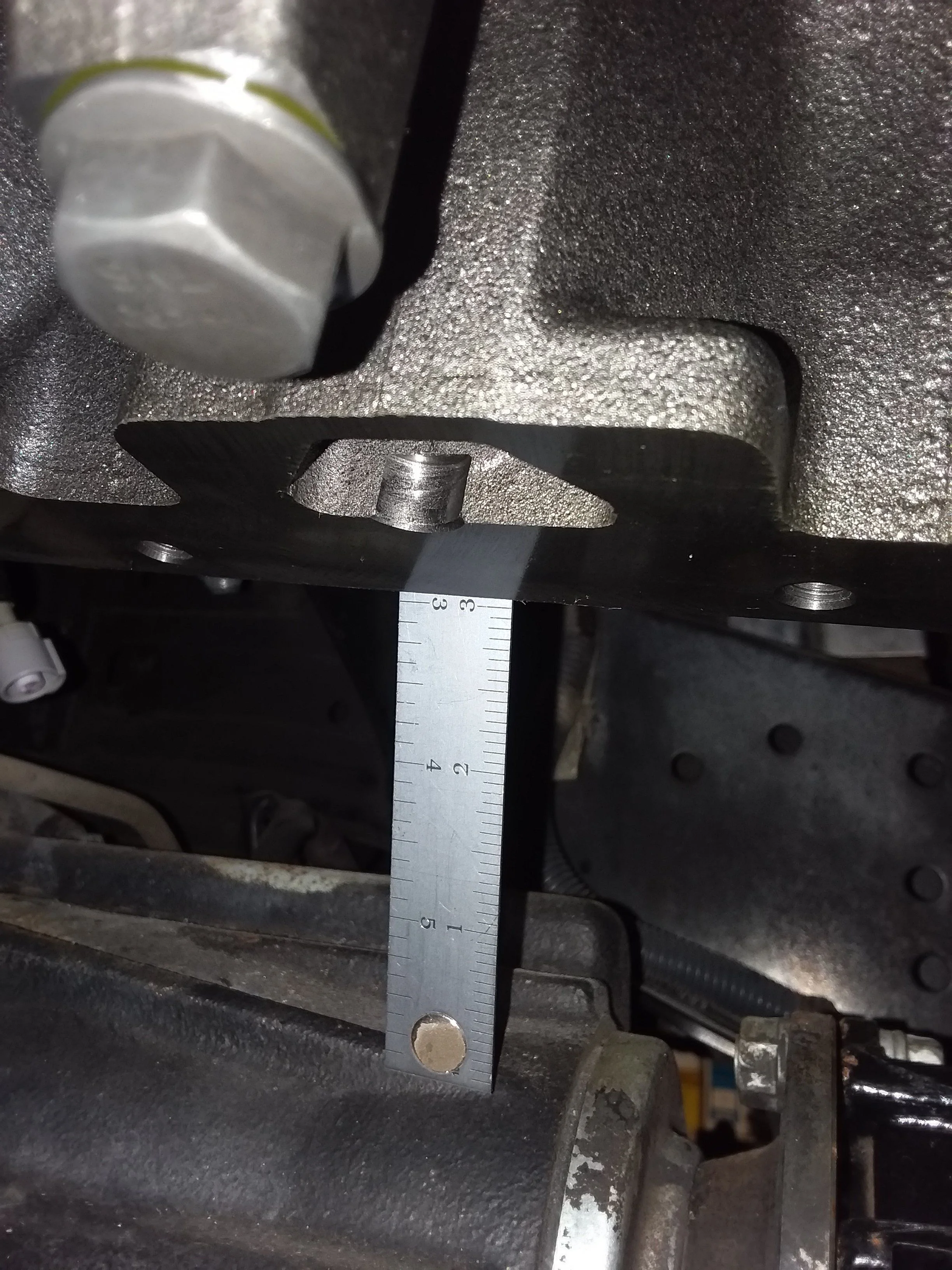
They were all done on a CNC machine, not my machine.
Follow along with the video below to see how to install our site as a web app on your home screen.
Note: This feature may not be available in some browsers.
This site may earn a commission from merchant affiliate
links, including eBay, Amazon, Skimlinks, and others.
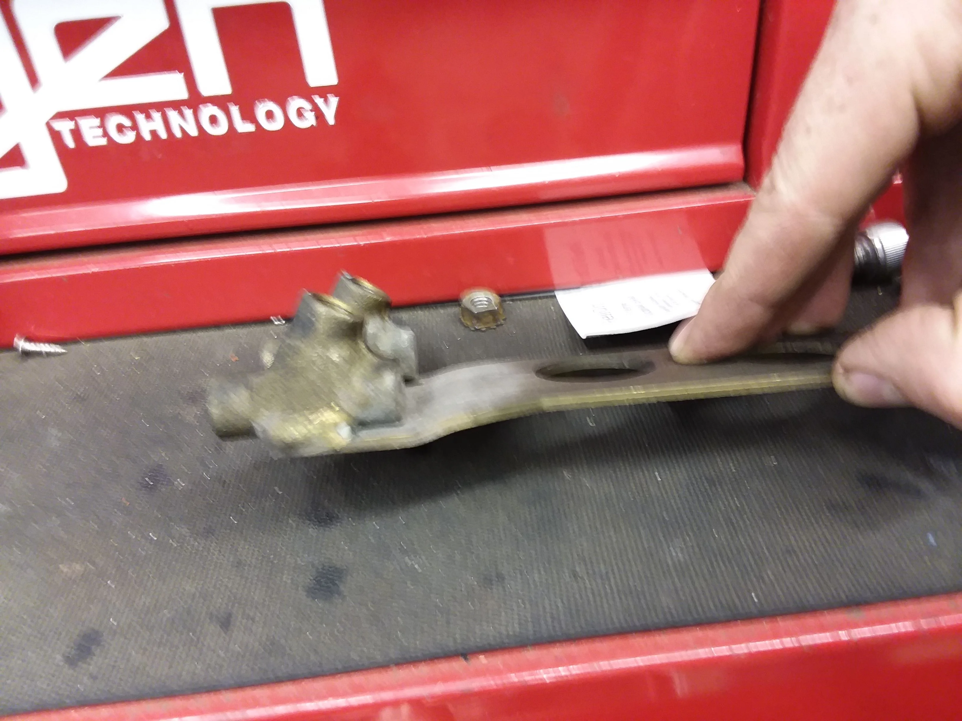
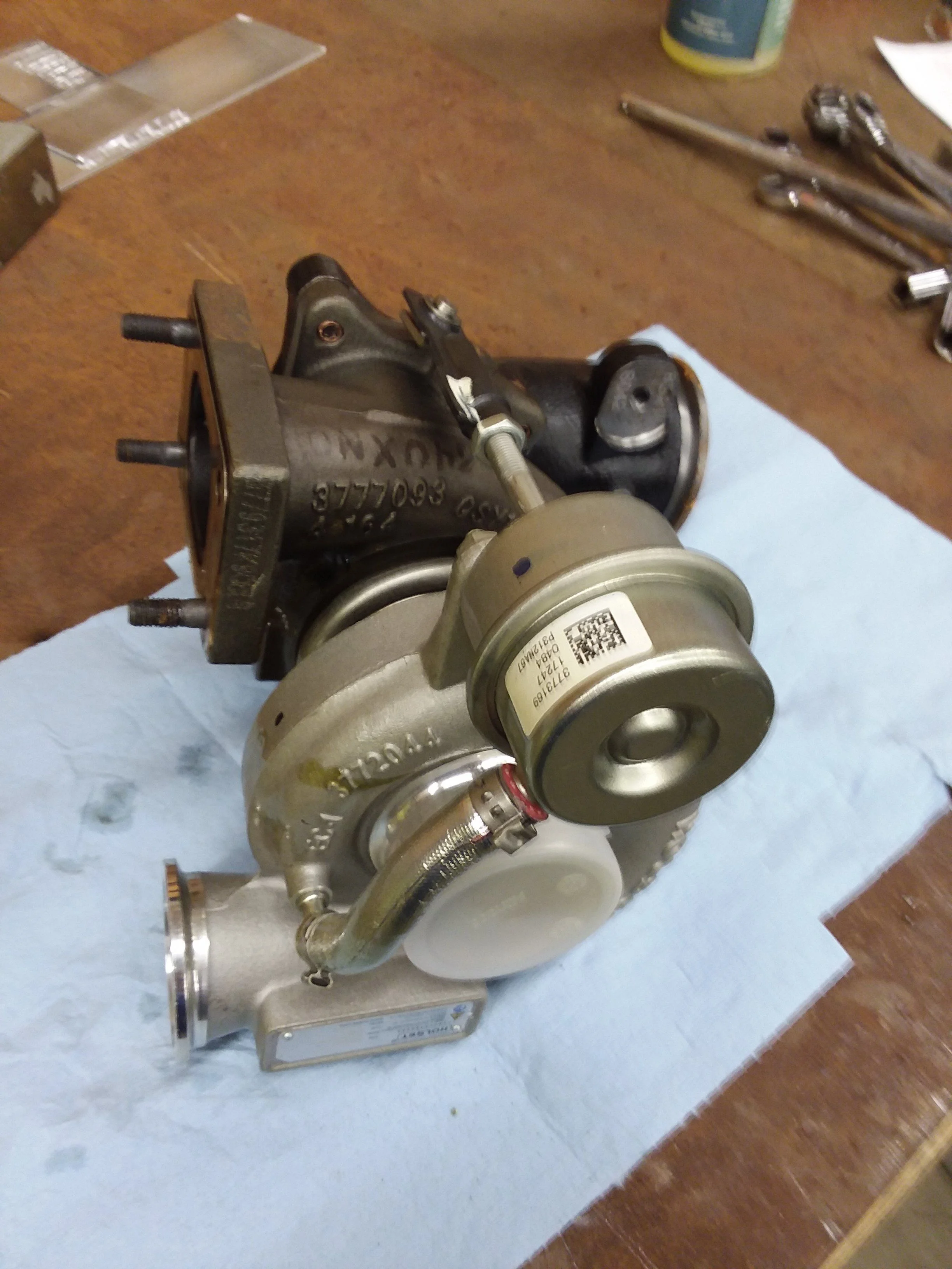
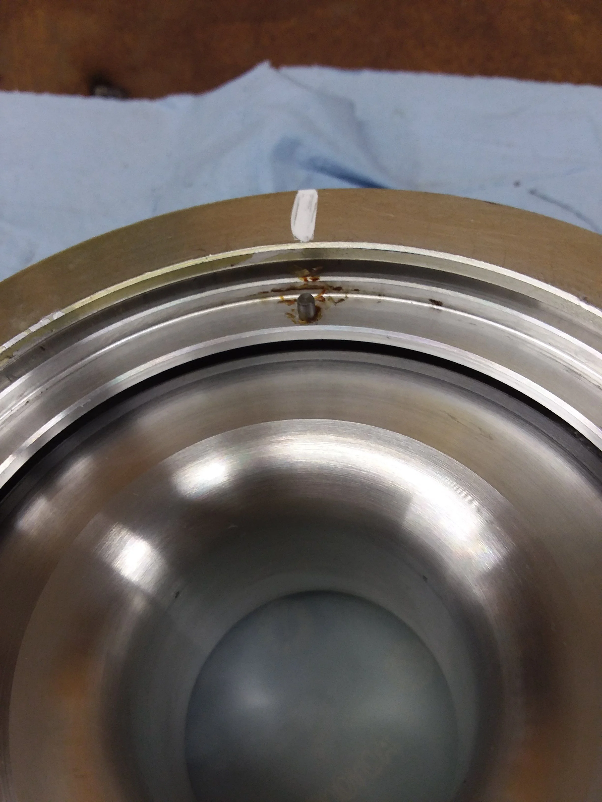
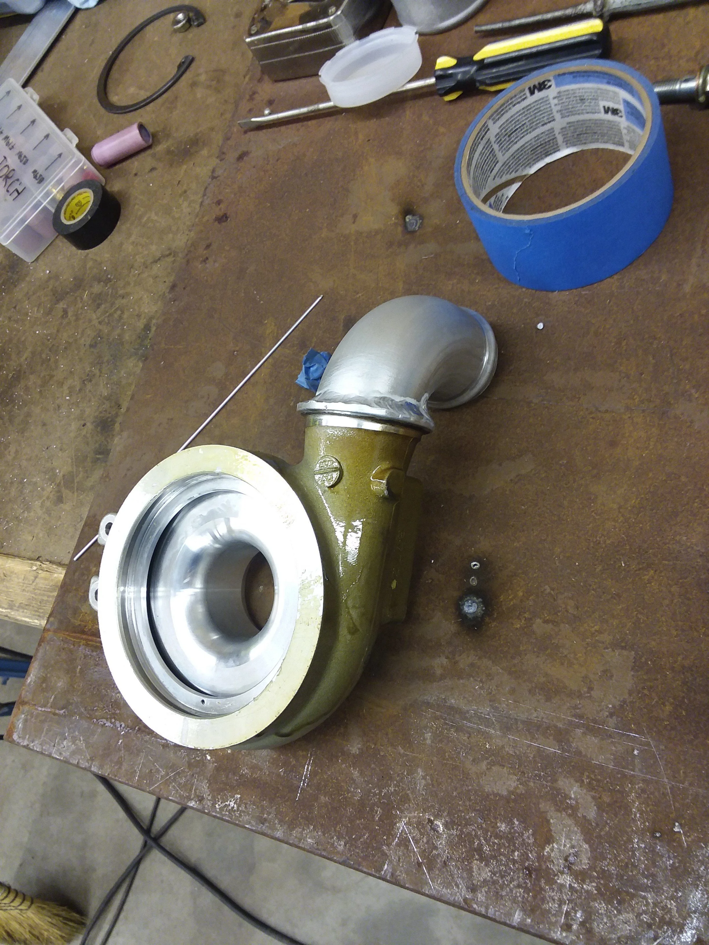
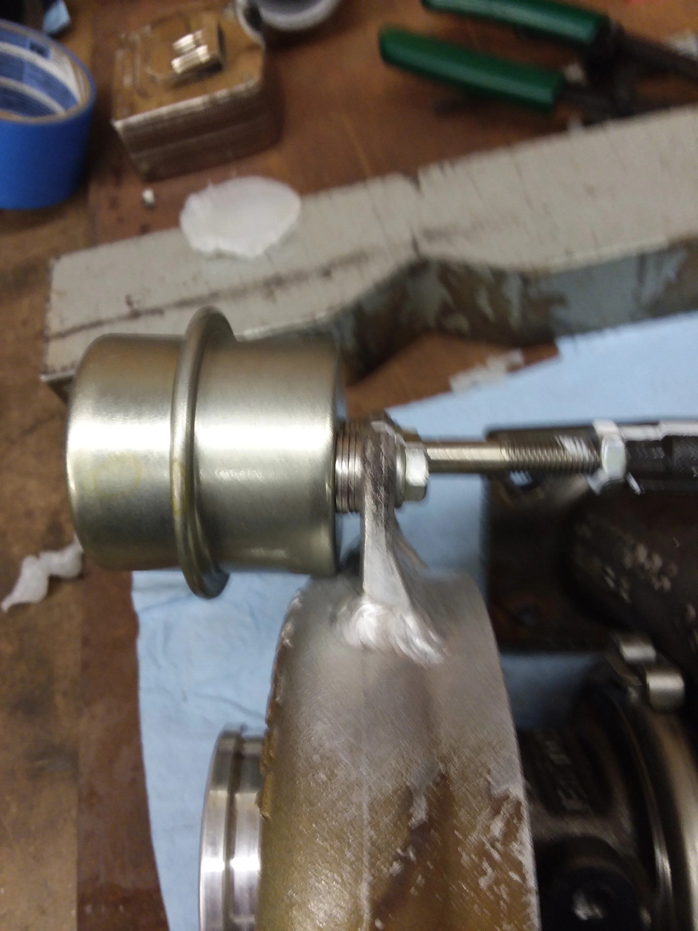
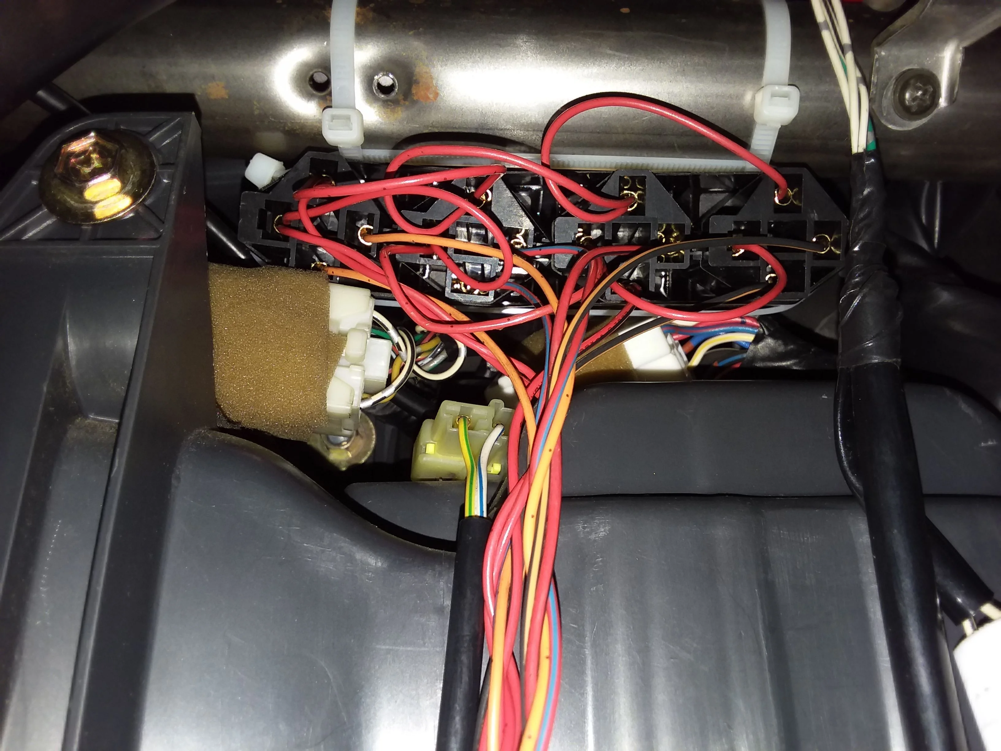
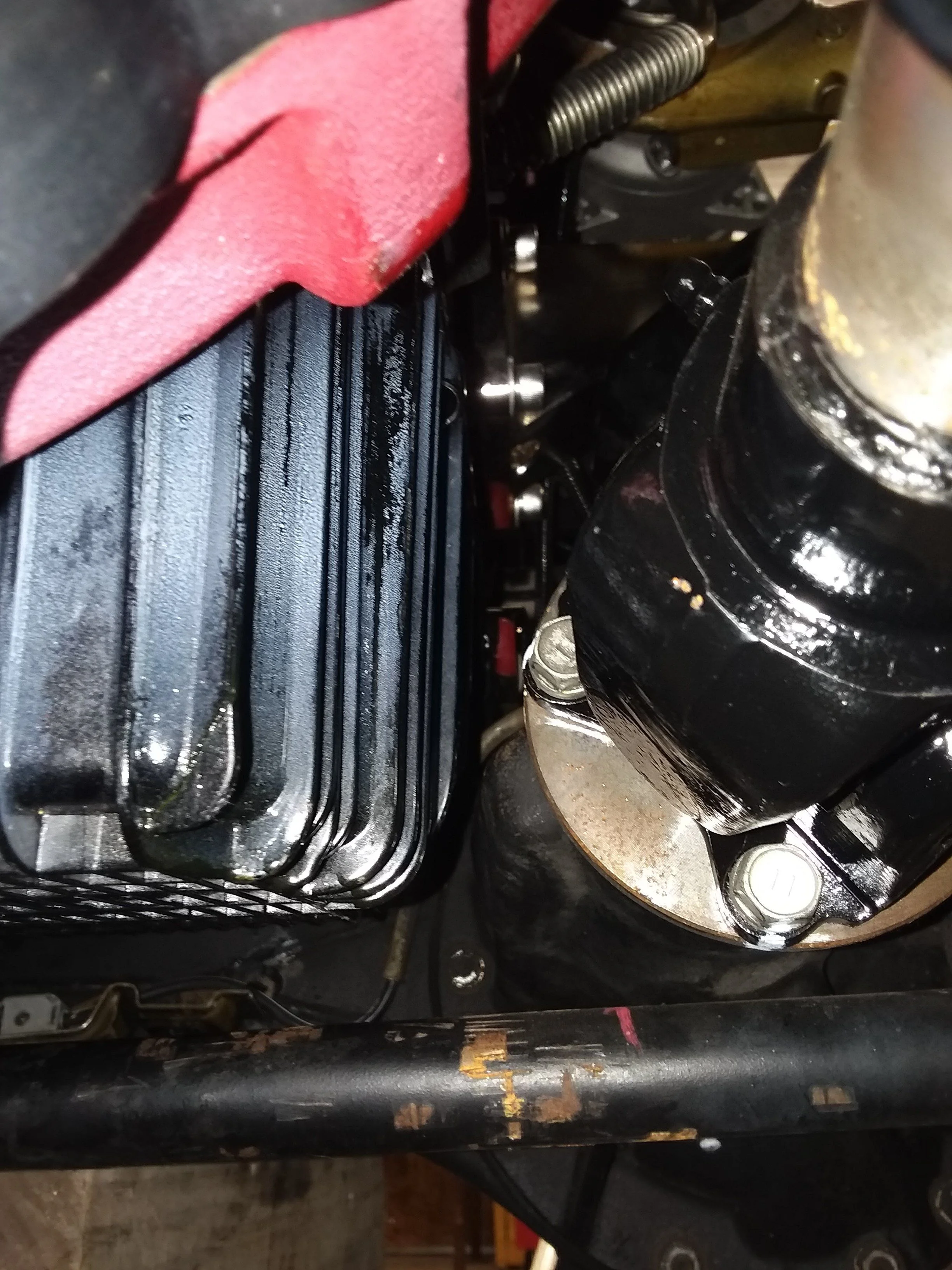
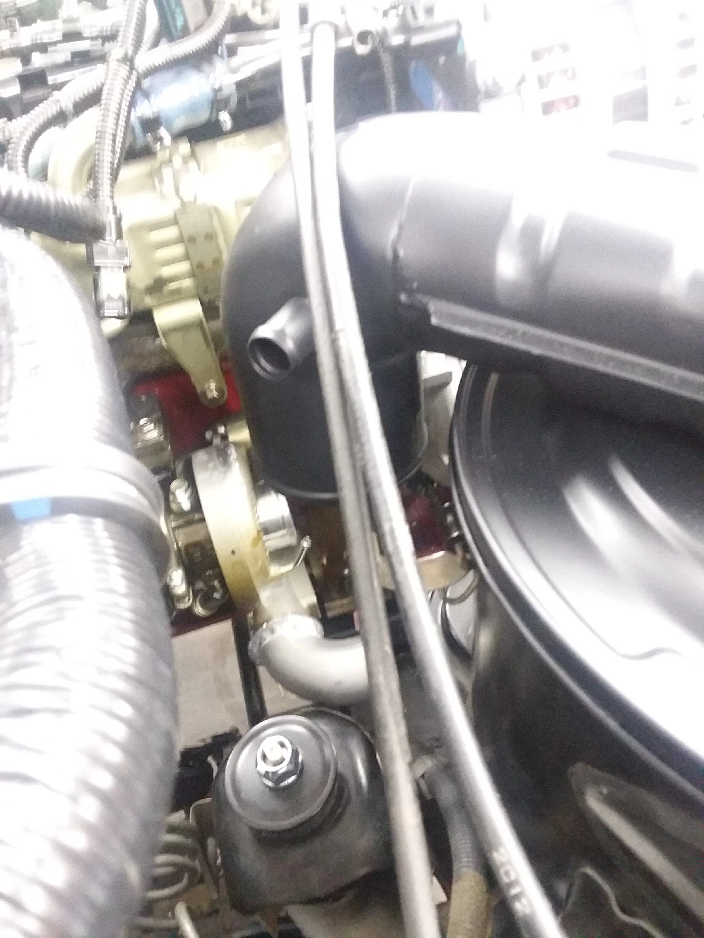
Did you put the spring back in the turbo to keep the compressor housing from turning? The snap ring that holds my housing on is so tight I cant see the need for a mechanical constrain to keep things aligned.Looking good. I had to pull that same pin out of my HE351 so I could clock it also. I thought about doing what you did with the waste gate but went with a modified spring actuator instead. I can weld steel at home. Welding aluminum is not in my wheel house yet.
No spring. I only have the snap ring and threw the pin away. It was not fun getting off and on. Broke the ends off the snap ring pliers. I prefer the ring that I can get off with channel locks like on my HX35.Did you put the spring back in the turbo to keep the compressor housing from turning? The snap ring that holds my housing on is so tight I cant see the need for a mechanical constrain to keep things aligned.
I have the feeling the pin is there to make sure people on the assembly line don't put it together in the wrong way, nothing more nothing less than that.
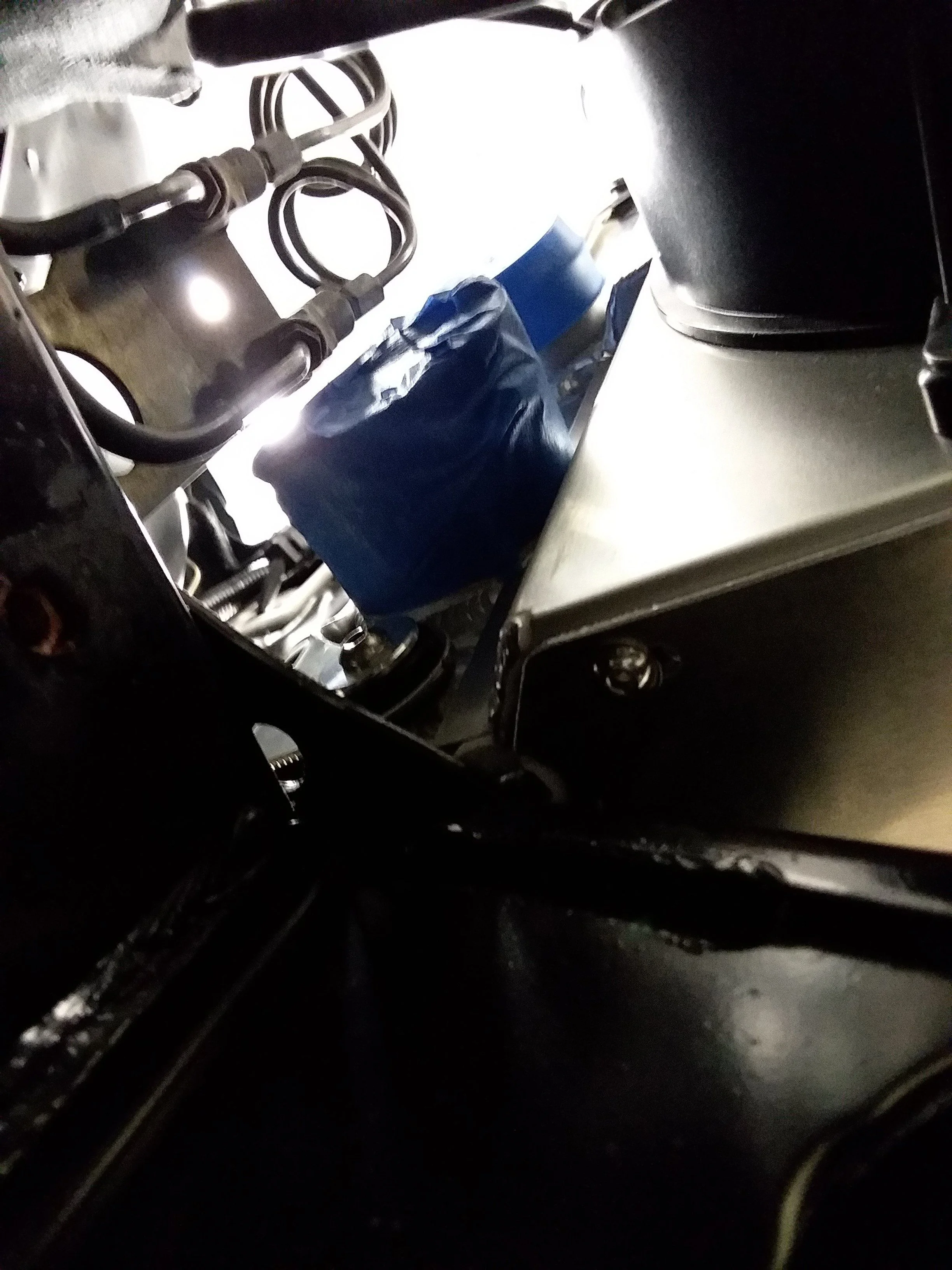
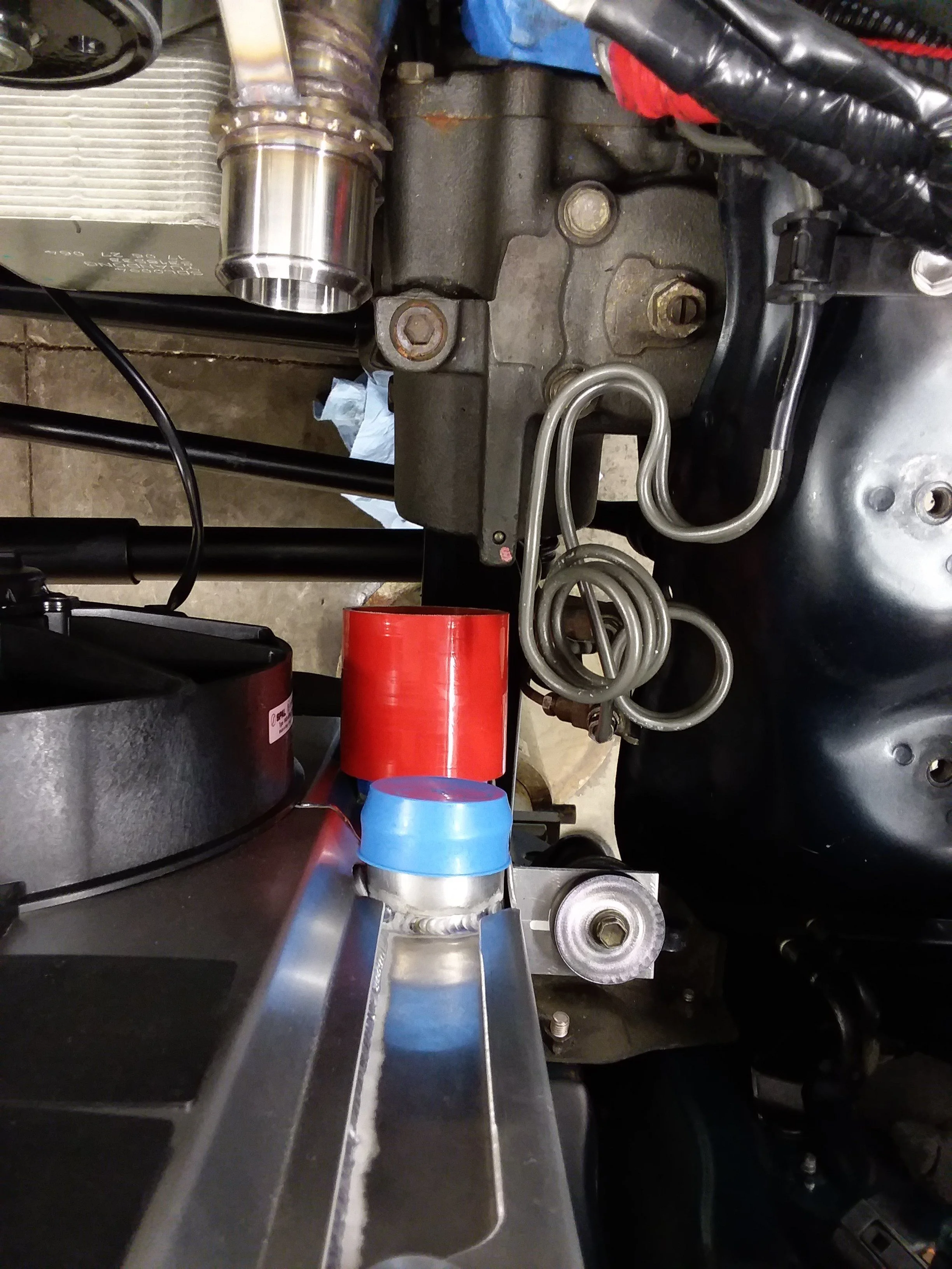
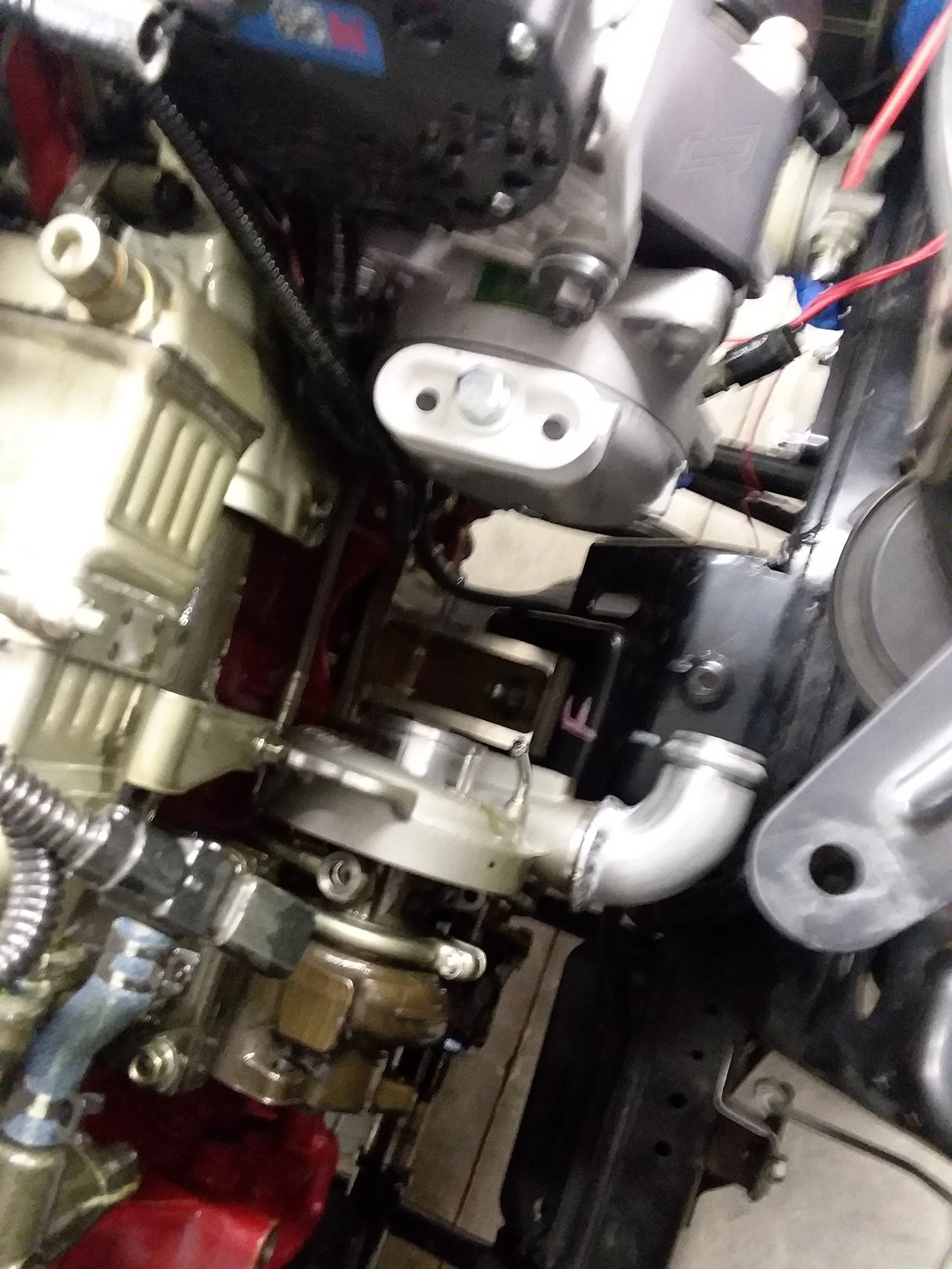
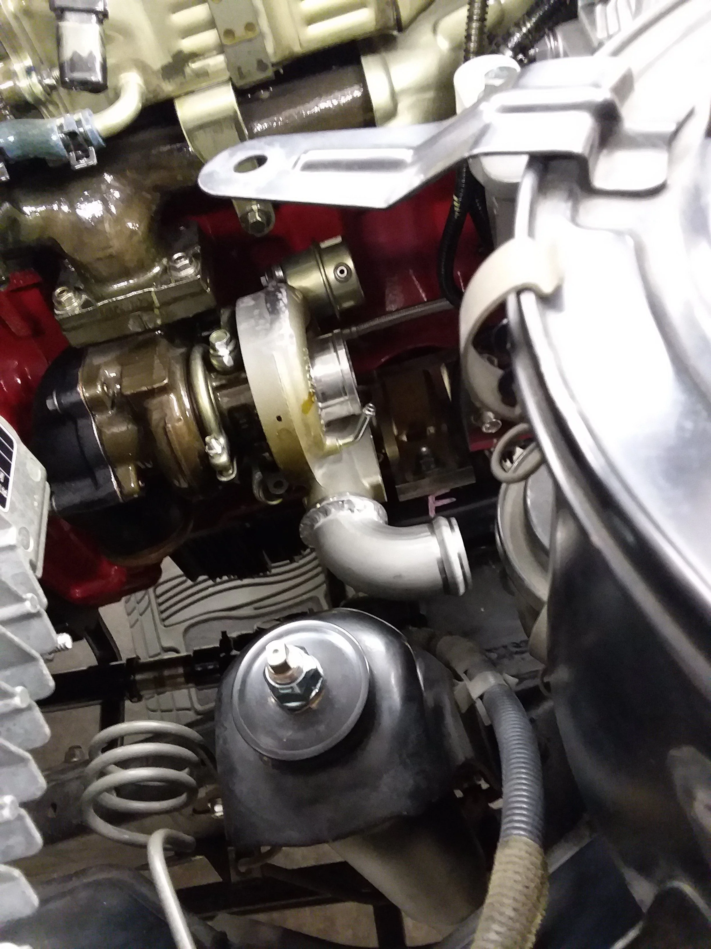
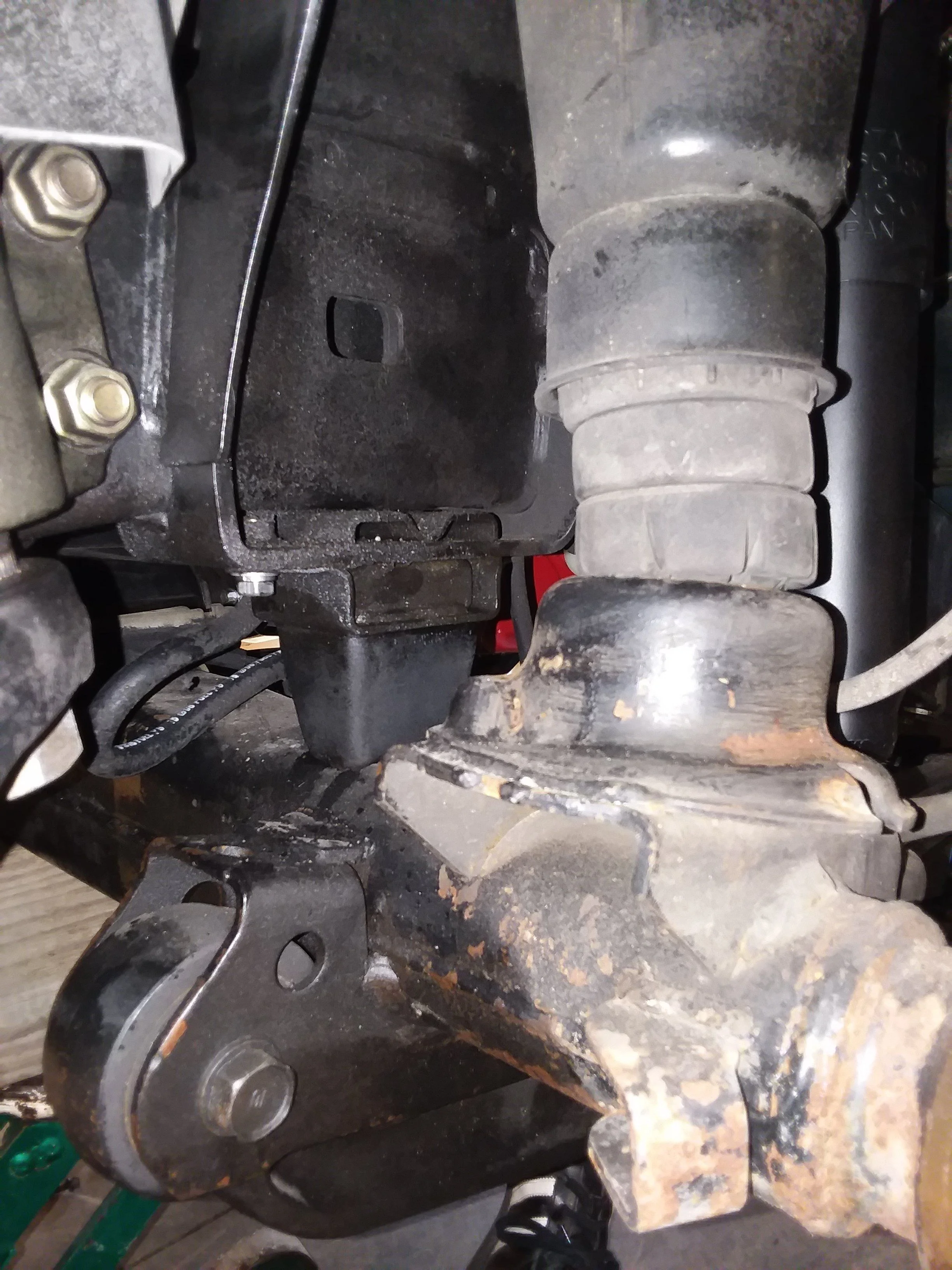
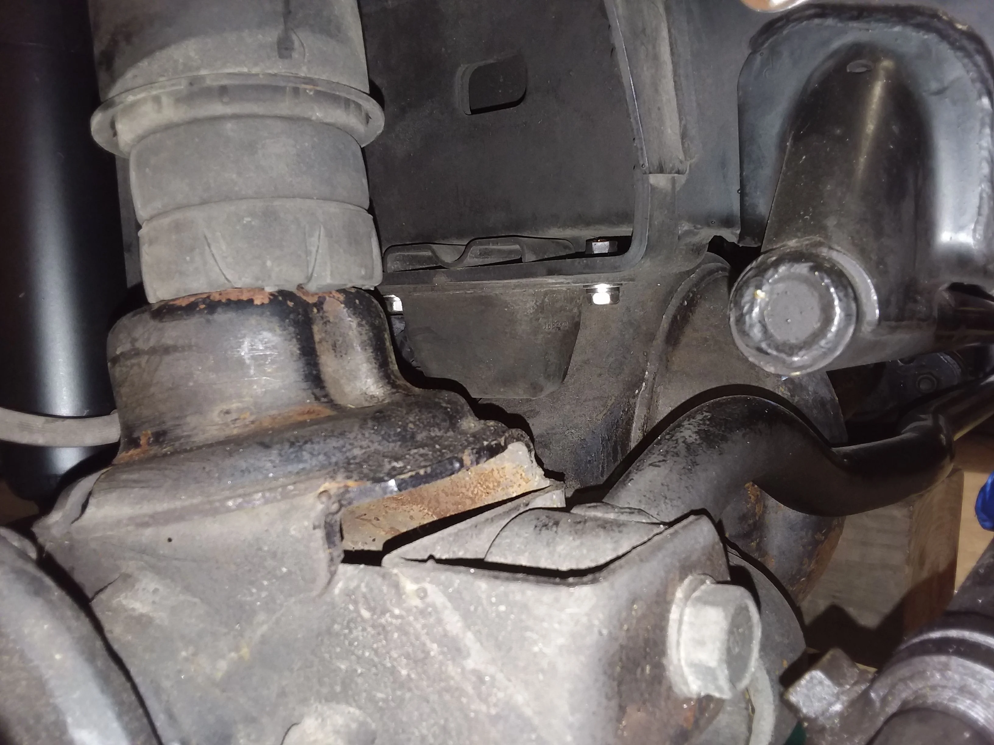
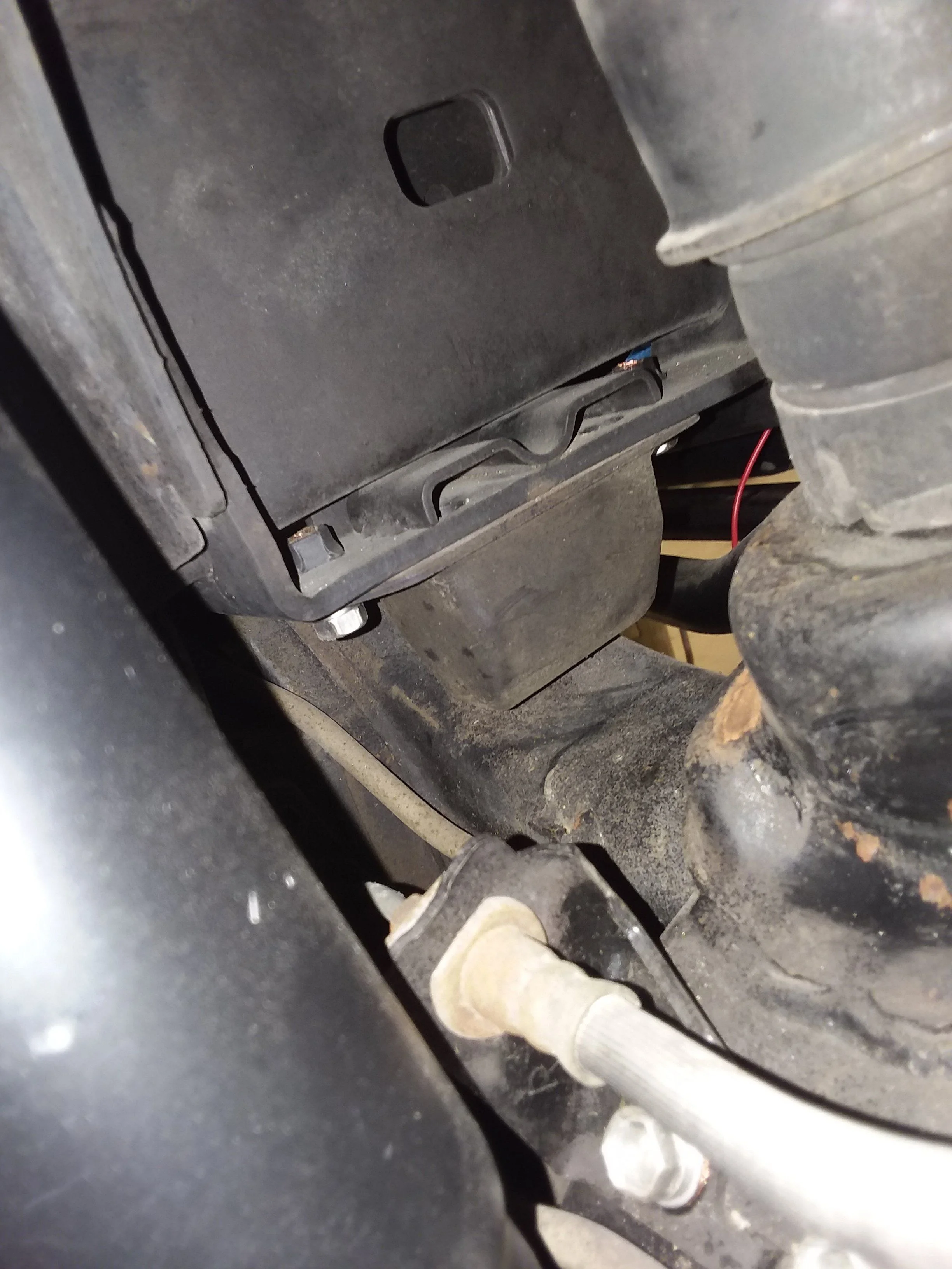
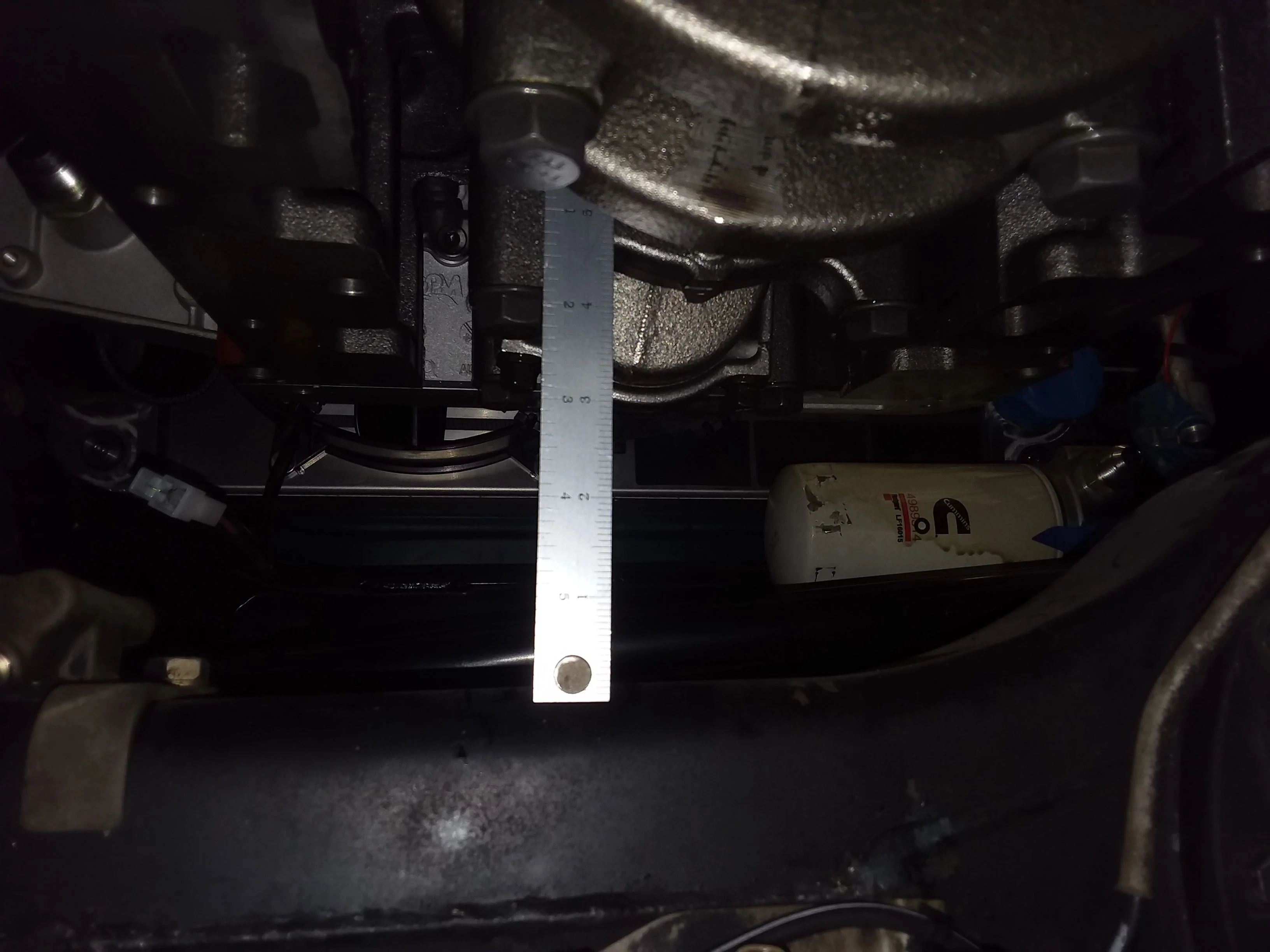
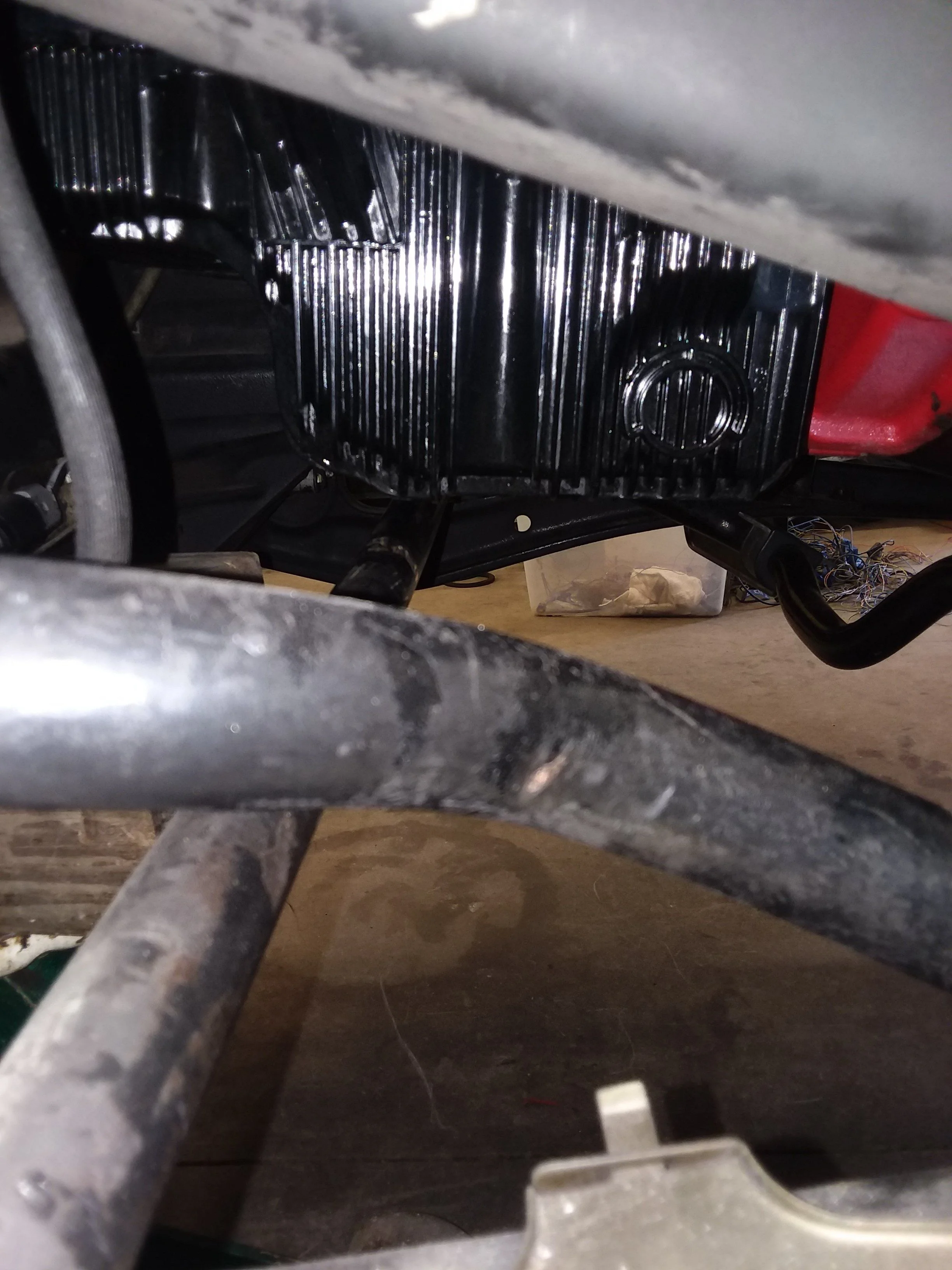
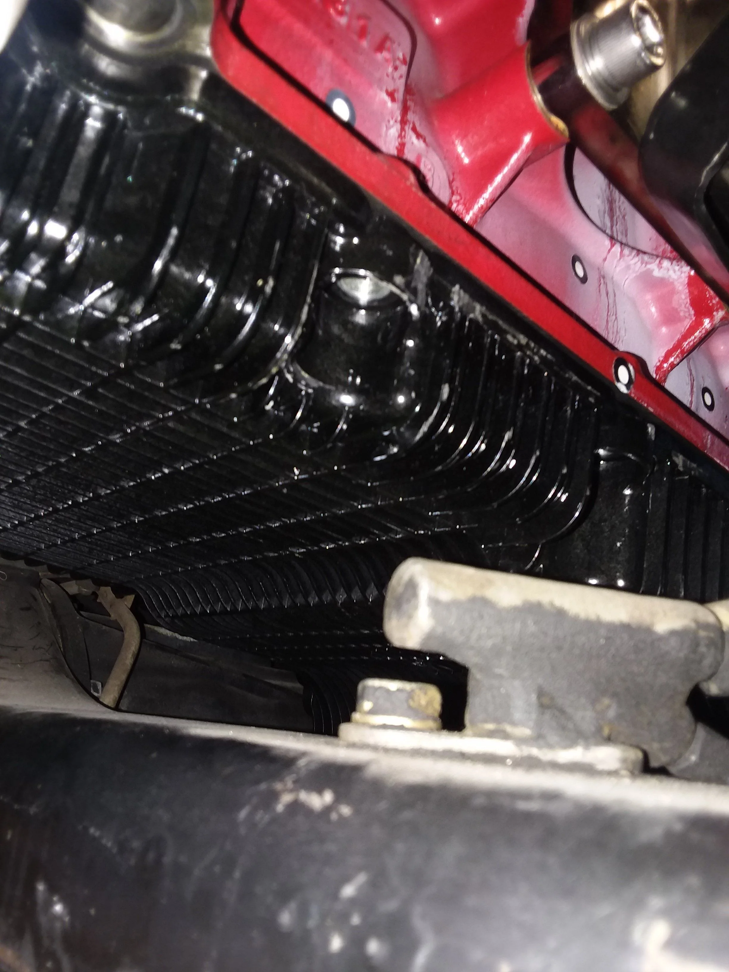
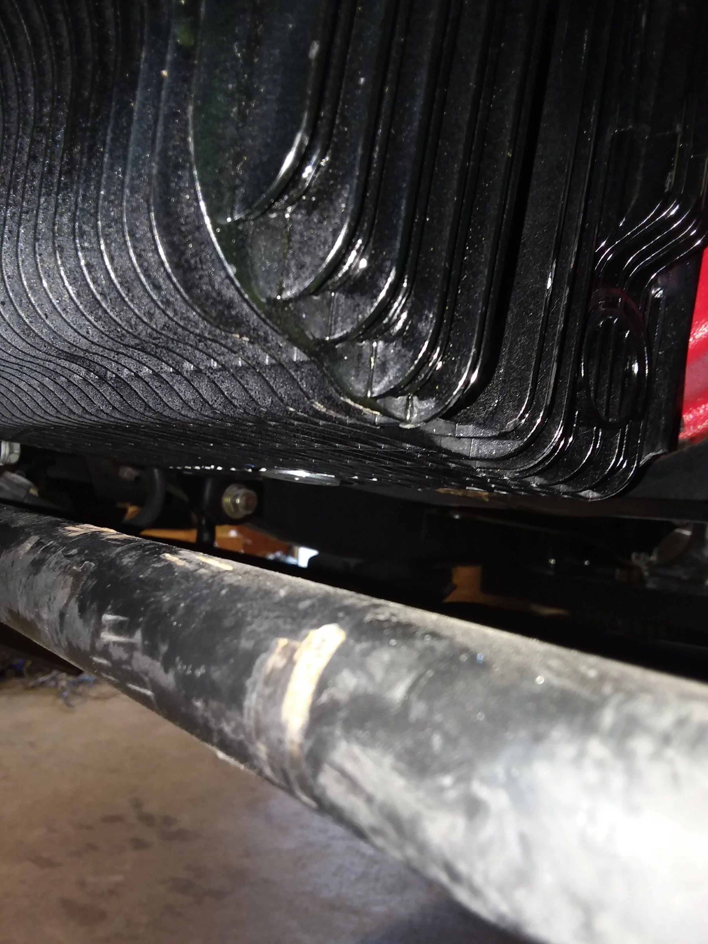
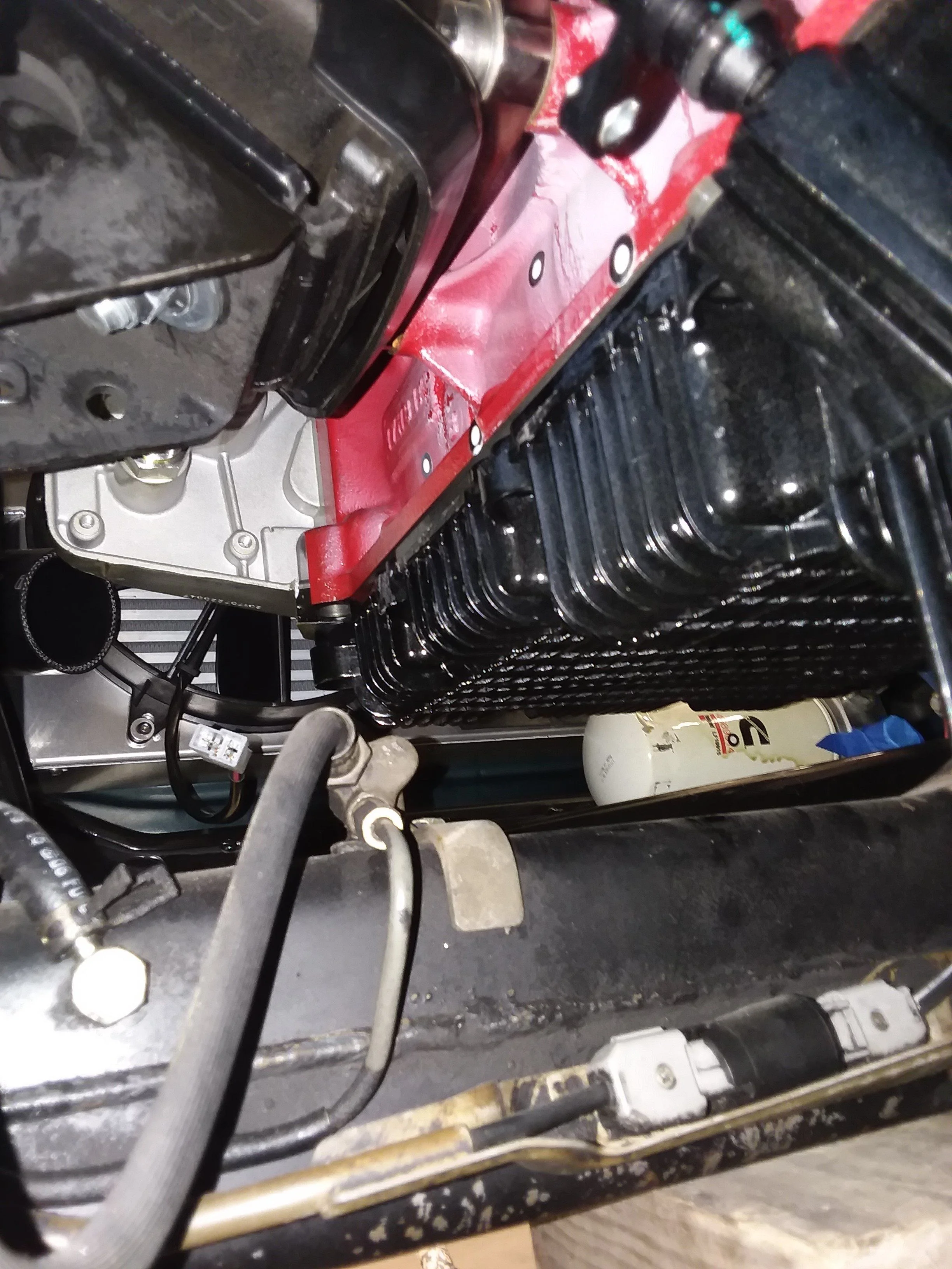
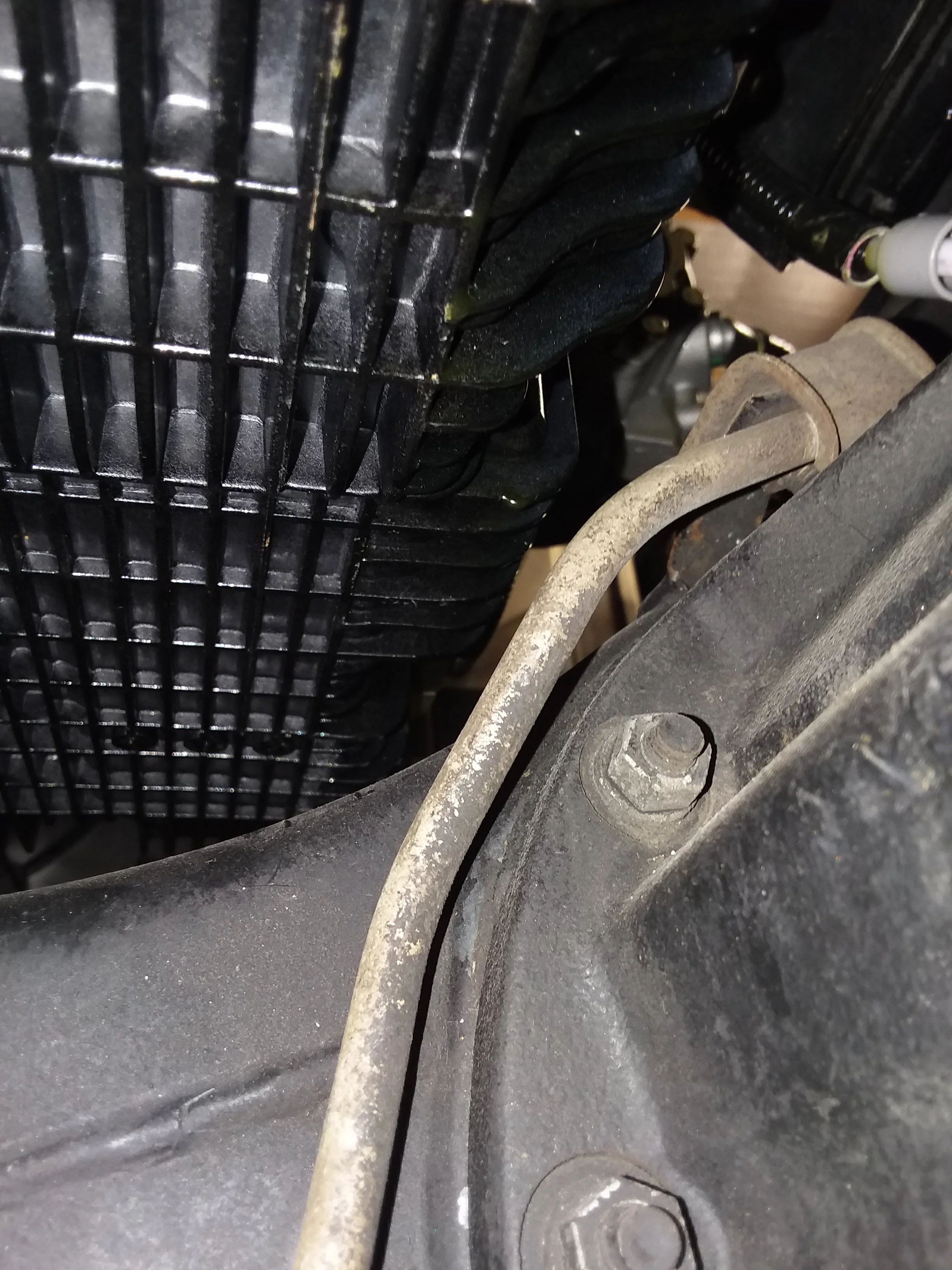
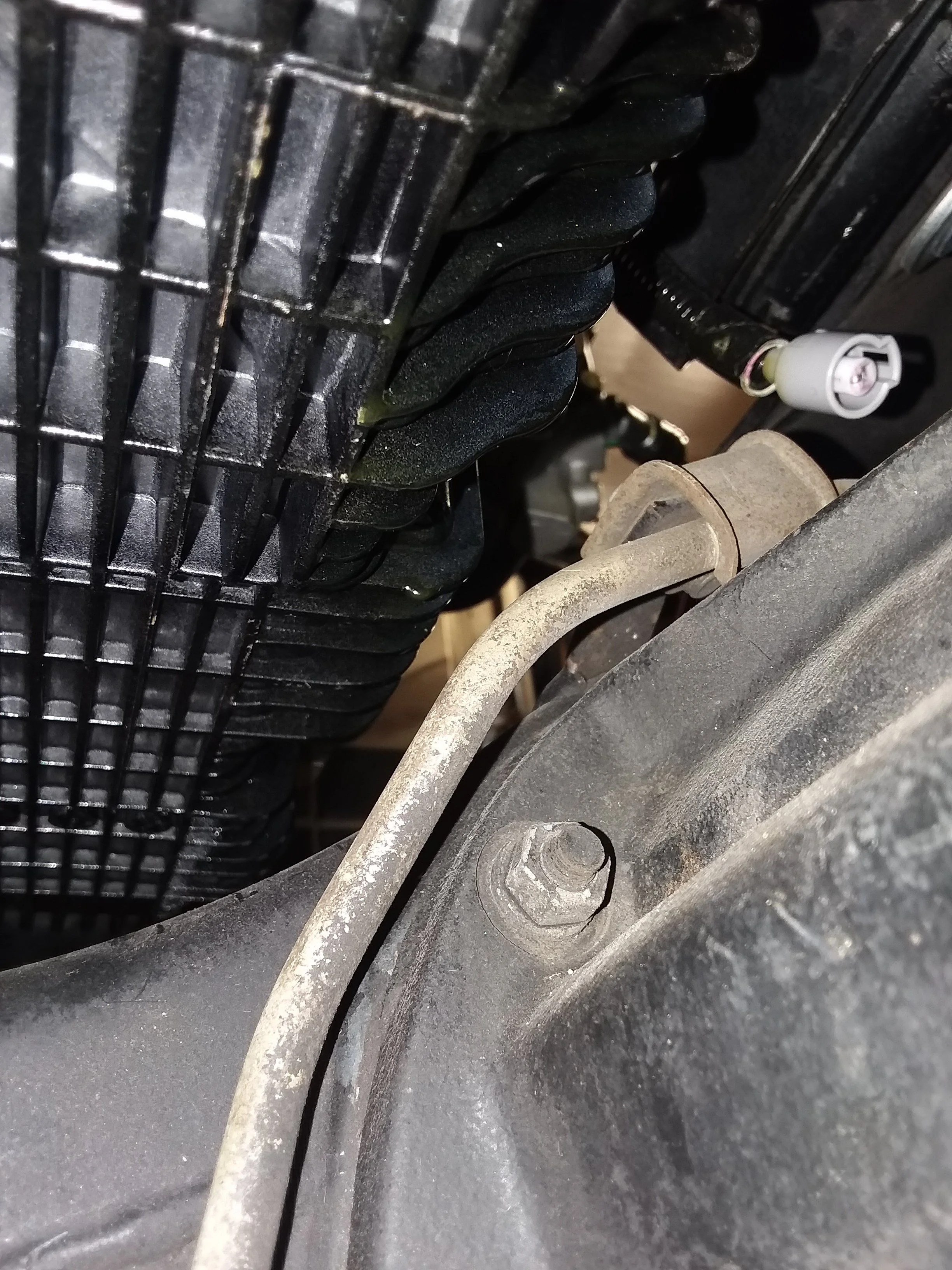
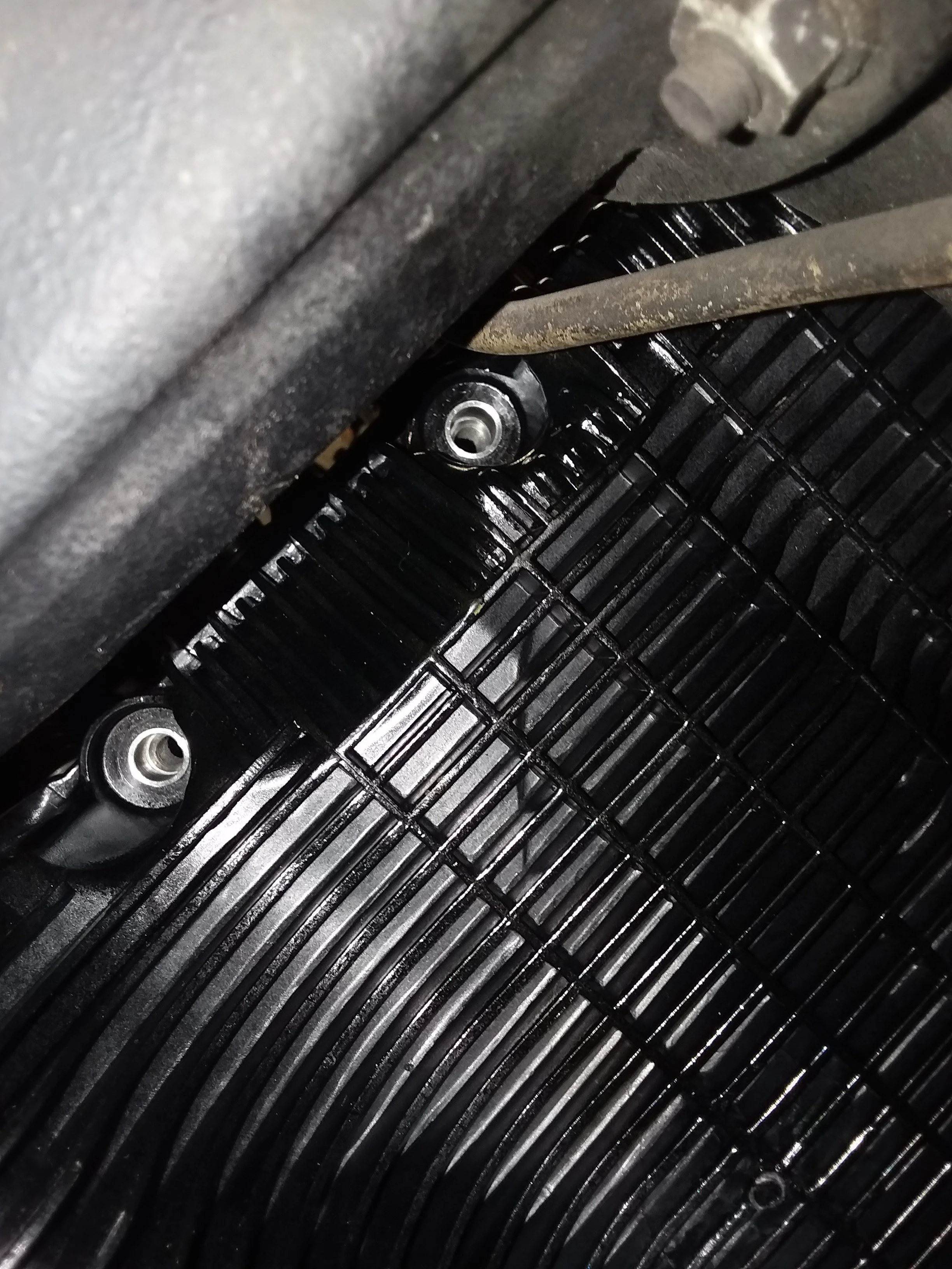
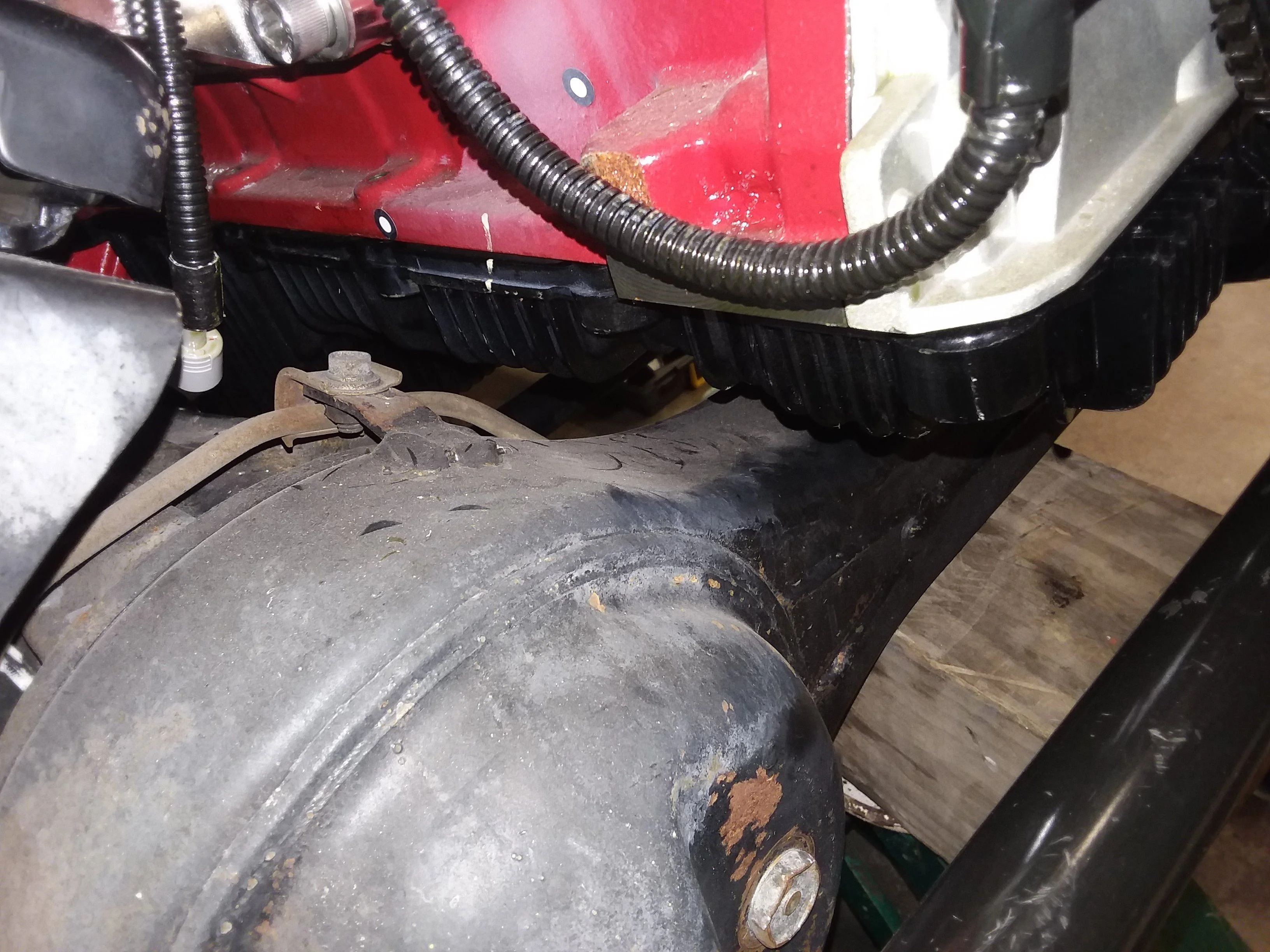
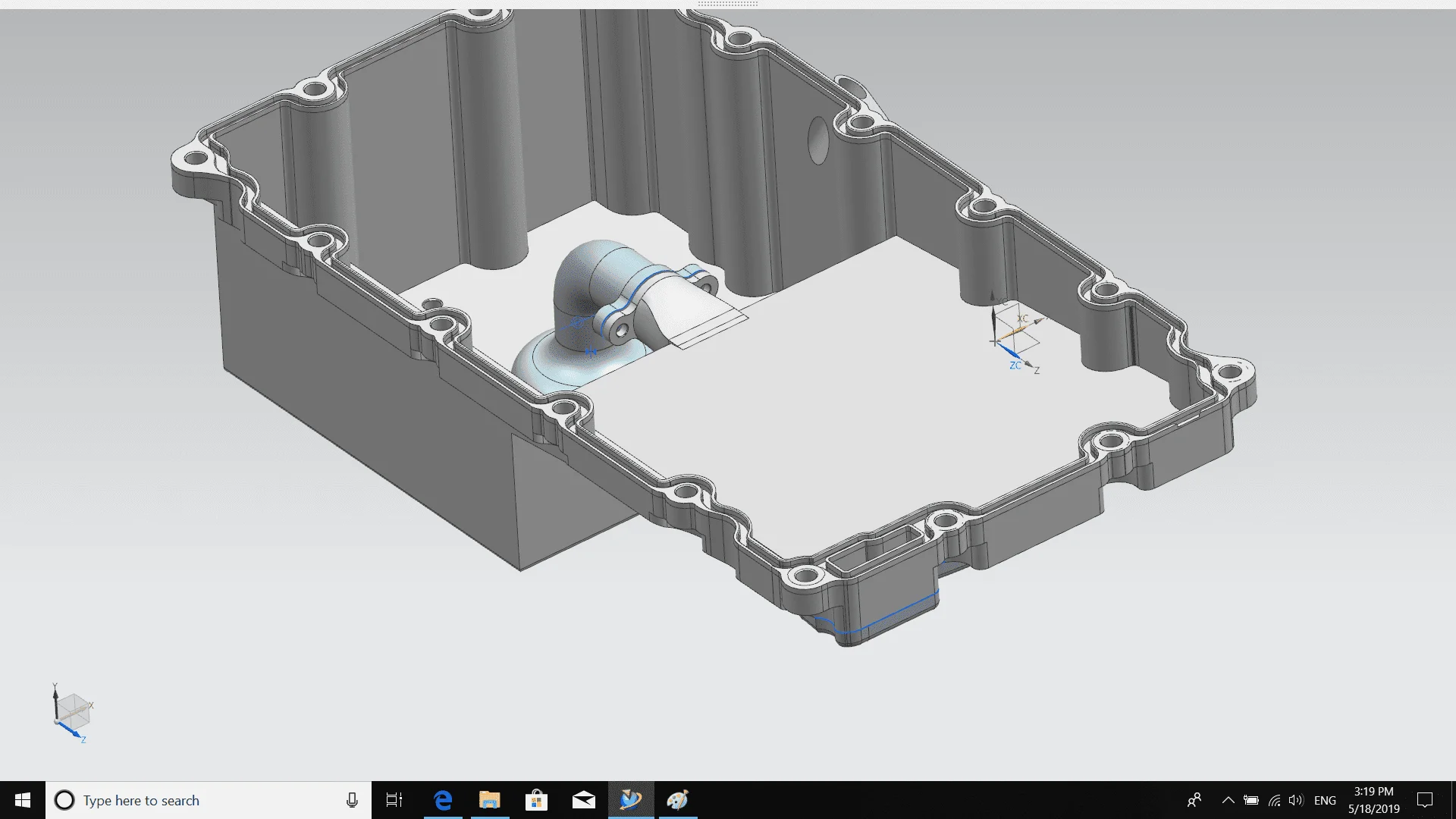
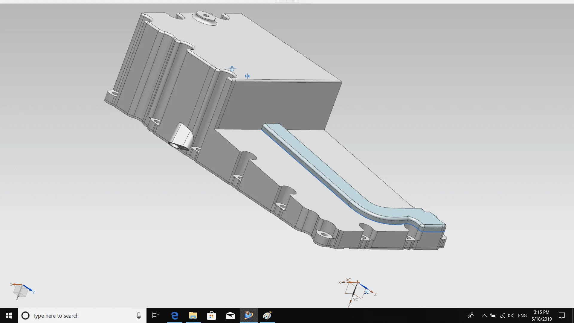
That is one of the things I don't like about the R2.8 is that plastic oil pan you get one unfriendly rock and it's going to be a bad day, I have picked up rocks and dinged my steel inter cooler tube. I wish you luck and success, with your adventure