How NOT to restore the FJ40 (1 Viewer)

This site may earn a commission from merchant affiliate
links, including eBay, Amazon, Skimlinks, and others.

I don't think lead had anything to do with compression, that would be octane. Lead was used to lubricate the valves, mostly the exhaust IIRC. John
Tetraethyl lead as an additive raises the octane, which means you can run higher compression before knocking occurs, and it also deposited a small amount of metallic lead on the exhaust valve seat after the burn. The small deposits were enough to stop the very hot exhaust valve trying to fuse itself to the head, and then tearing that fused area out when the valve next opened.
That weld/tear was what created valve seat erosion when the lead was removed from fuel. Modern castings / different metallurgy solves the problem without using additives.
 
just a question i was looking in the parts catalog at the piston part #'s and i was curious
about what the difference between the US engine and a Canadian engine is. they list different part numbers for the pistons depending on what market the engine was built for .

sorry i am not a 2F guy . see pic of #'s this is just a few of the numbers listed. ..


,,,,,,,,,,,,,
epc.jpg
 
Block prep

Spent an entire day on block prep. An engine is only as good as the foundation.

The 84-earlier engines use welch plugs to close the main oil gallery. The plugs tend to leak (as they were in the old block). To fix this, the block is tapped for the big pipe plugs on the front & back end.

DSC07669_zpsfddd7df9.jpg


On the back the new allen plug is visible to the right. On the left is the correct shallow cup plug that closes the rear of the cam bore. This in contrast to the deep, american size plug that was used by the previous builder, which contributed to the early demise of the old cam.

DSC07673_zpsb57254f4.jpg


Then all of the threaded holes get chased out, dipstick tube painted and installed, block drainplug cleaned & reinstalled.

DSC07667_zps625e85a7.jpg


Deburr main saddles and install new Japanese Mahle/Clevite/NDG bearings.

DSC07675_zpseab21ff8.jpg


More to come later. It's lunch thirty.:cheers:
 
You can eat your lunch off that thing ...
 
Looking good Jim
 
More pics needed!
 
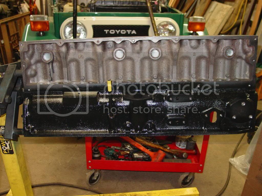
As was pointed out, this is how NOT to restore. So the focus will remain on identifying and repairing the many errors made in the "restoration".

Already covered:
Bore block to correct size so pistons don't smear in cylinders.
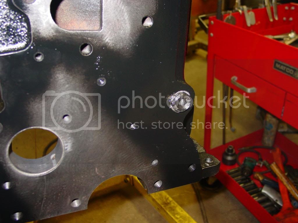
Install correct cam plug so cam will not stick out front of block.
Replace leaking oil plugs w/ allen plugs.
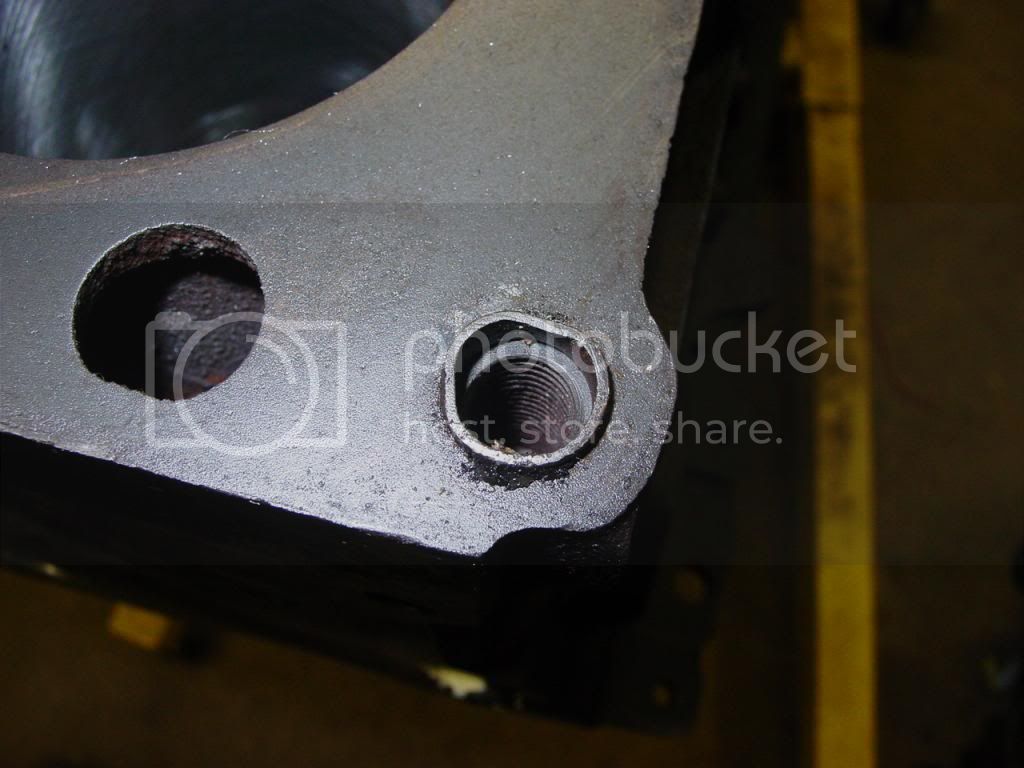
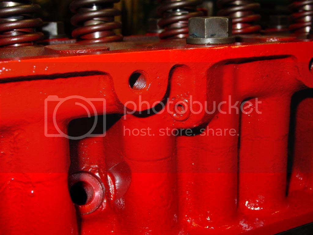
Chase all threaded holes, so the bolts aren't bottoming out against old rust & RTV in the bottom of the bolt holes.

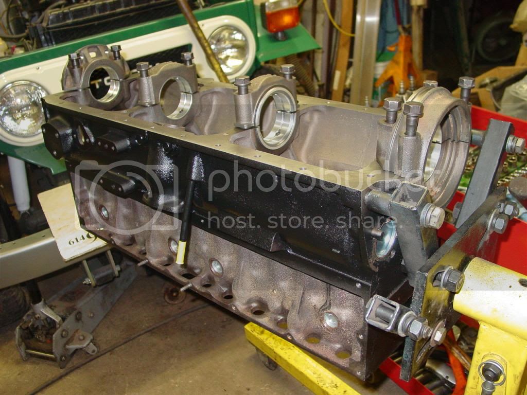
Next up is the crankshaft. The original crank was already cut .25mm undersize, and badly. It also had a rear seal surface was too far undersize.
A better crank was dug up, and turned .25mm under by a competent machinist. The journals are straight (not swaybacked) and the seal surface is polished, but not excessively.

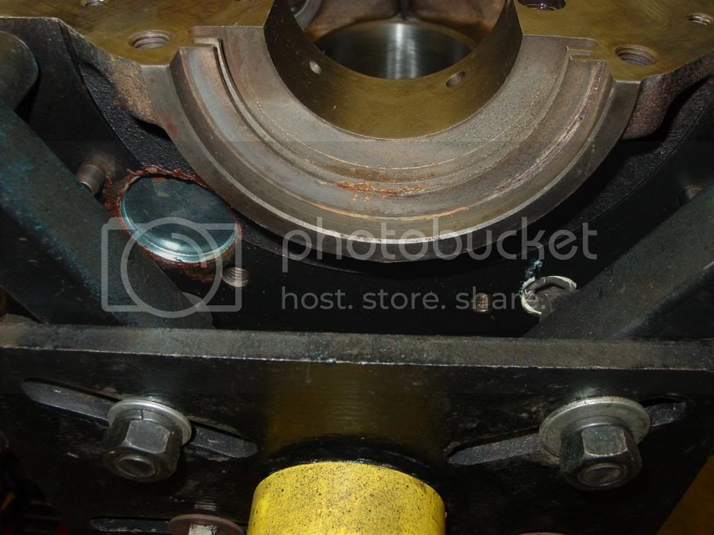
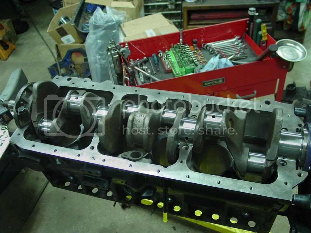
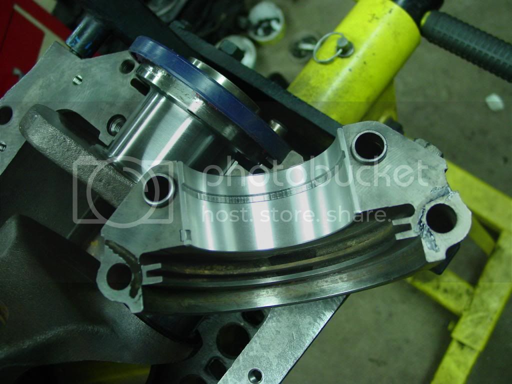
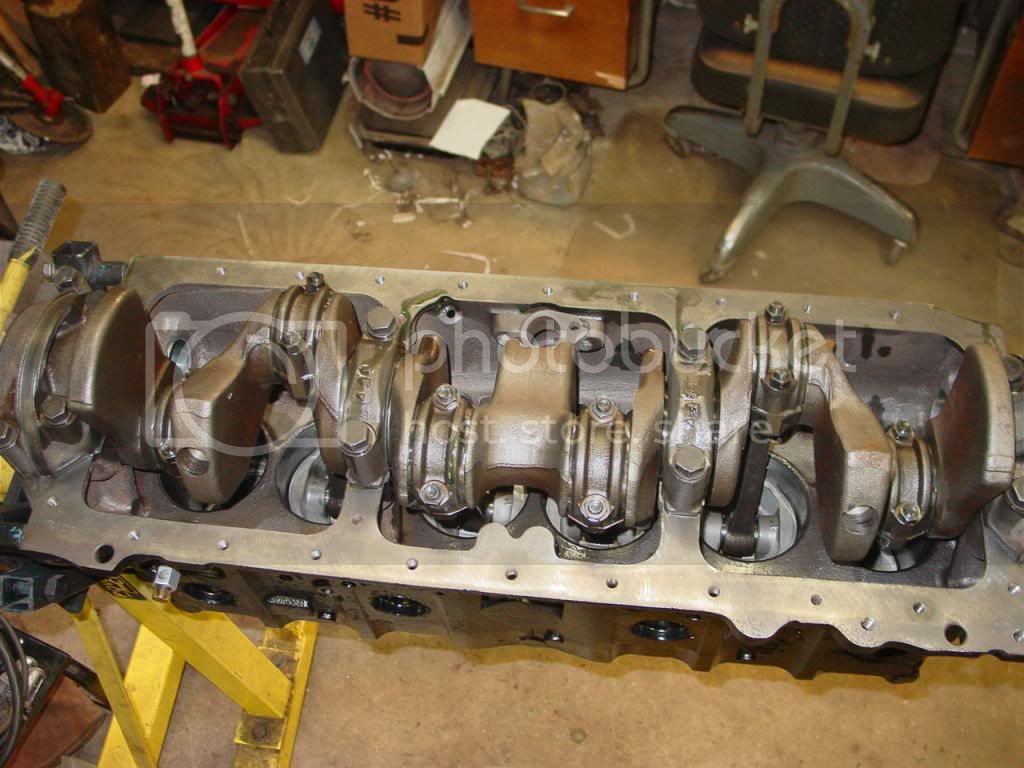
Crank is cleaned a final time, the bearings smeared w/ assembly lube and crank laid in the block. Note that the rear main seal is installed at the same time as the crank. It is not beaten into place later, which could ding the rear of the crank, making FW installation more difficult. Like it was upon disassembly.:rolleyes:

DSC07677_zps28d9ef6f.jpg


Also note the tiny smear of permatex#2 that is applied to seal the main cap between the rear seal and oilpan corner.

DSC07678_zps04a8204d.jpg


Smear lube on main bearings in caps, install and torque caps using a TORQUE WRENCH this time.
As QC, verify that crank still spins, and end play is detectable but not excessive.

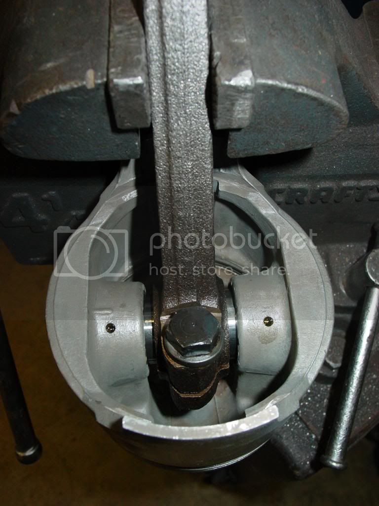
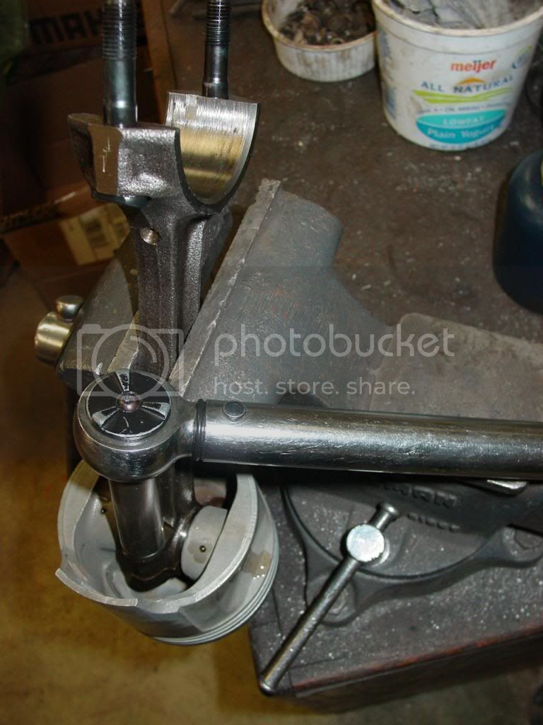
The rods from the old engine are re-usable. Clamp a rod in the vise, orient oil squirter hole toward cam, and notch on piston toward front. Apply oil to wristpin bore and slide pin through piston & rod.

DSC07682_zpsf83d413d.jpg


Center pin in rod, then TORQUE rod pinch bolt with a TORQUE WRENCH to 45ft-lbs.

DSC07681_zps3f4a3914.jpg


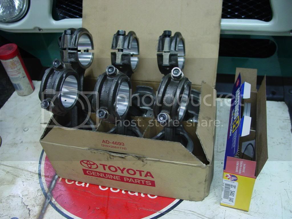
Do that 5 more times. With a TORQUE WRENCH. Until there is a box like this:

DSC07683_zps07bcc3c1.jpg


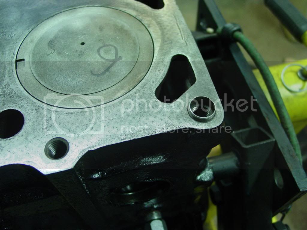
Grab a couple of those rings and stick them in the bore to be sure ring end gap is OK, then install rings onto the new used Mud-sourced 1mm O/S pistons. Line up ring gaps on pistons so they are staggered every 90* around piston, and no gap on the thrust faces. Saturate rings and bores with light lubricant (WD40), smear assembly lube on rod bearing, squeeze it with the ring compressor, and whack one in the block. Smear, squeeze and whack 5 more times, then TORQUE every rod cap and main bearing cap using a good torque wrench one more time.

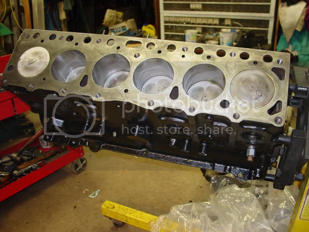
It should look something like this from the bottom:

DSC07686_zpsff7152aa.jpg


Note that in the top view, the correct pistons are in the correct holes. They are each measured for max diameter, then the bore is finished to provide just enough clearance for that piston. This is not always necessary, like for a set of new Toyota pistons. But for these used pistons of unknown provenance, it was a necessity.

DSC07684_zps790ae63f.jpg


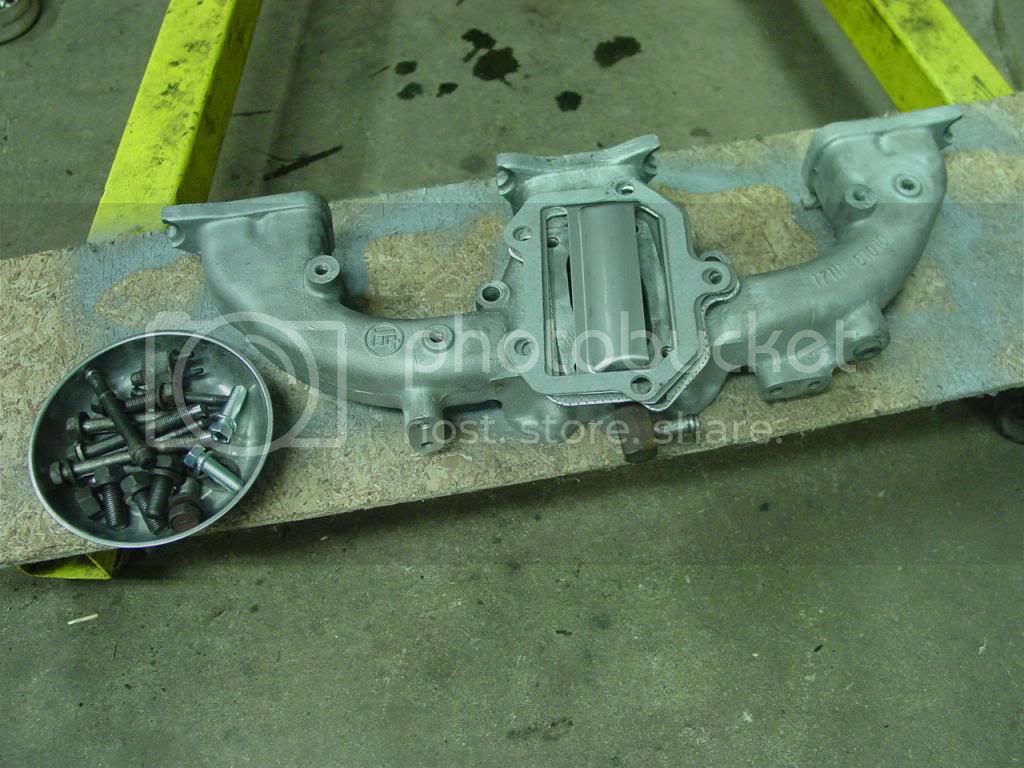
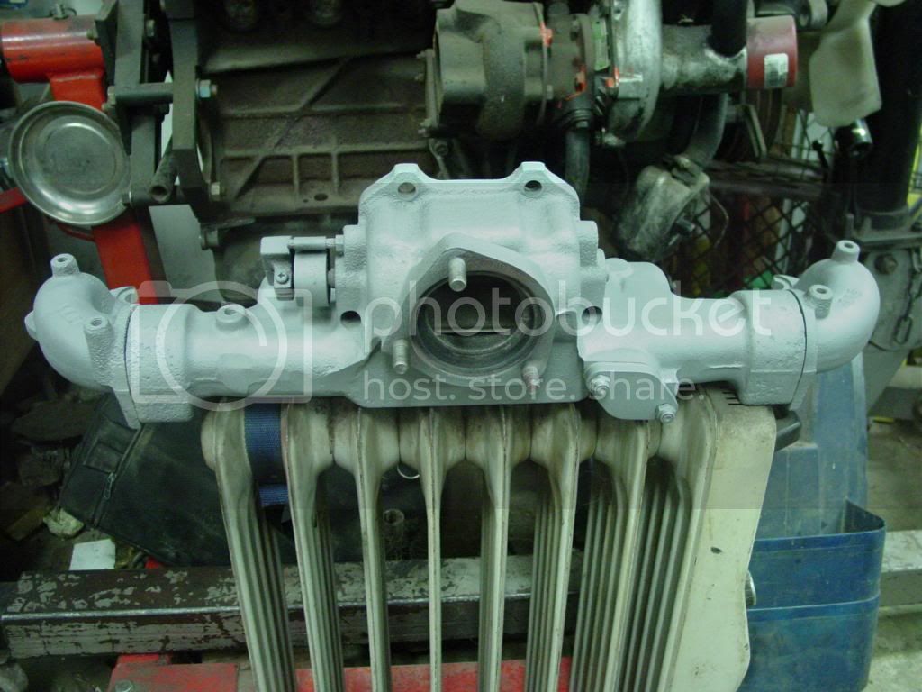
Next up is getting the fuggled manifolds back in order. Tomorrow.
 
Considering that I assembled my block last winter I think I did okay for the first block I've assembled in 20+ years but I would have loved to have had your tutorial then. Thanks Jim for the lesson.
 
Dang Jim, that block hasn't looked that nice in YEARS! I still liked the yellow paint better though...easier to see stuff down in the bottom of the engine compartment vs. the black hole next to a black block. :p

Nick
 
It won't be yellow, but there are colors coming.

Oh lord not another Big Gay 2F engine! :grinpimp:

If I ever get to build my dream cruiser I know where I'm getting the engine work done... Just got to find that turbo for the 2F... ;)
 
The manifold package is pretty simple. An aluminum intake is bolted to the top of the iron exhaust, and held on the engine by six M12 fasteners.

On teardown the following deficiencies were noted:
Wrong 12mm mani bolts in head.
Missing 2 of 5 inter manifold bolts, 1 of 5 intermanifold bolts had threads torn off.
Missing 1 of 2 inter gaskets and the stainless separator plate, resulting in half holes of manifolds badly misaligned.
Head/mani stud threads mashed from prying off misaligned manifolds.
Missing one EGR outlet tube locknuts.
one downpipe stud replaced w/ bolt, one stud rusted to nut, making it a bolt.
Significant manifold leaks everywhere: head, EGR tube, downpipe

Addressing these items in order:
The manifold bolts had been interchanged with the similar engine mount bolts. Cleaned up correct bolts and put them in the manifold bucket.
Got 2 new intermani bolts & separator plate from CDan.
2 new intermani gaskets came in gasket kit.
Chased threads on studs w/ dies, they straightened up good enough. Worst damage was right against head, where thread is not needed.
Dug 2 correct EGR locknuts out of used manifold bolt bin.
Ordered 2 new exh studs and 3 locknuts from Cdan.
Will reassemble correctly w/ graphlex manifold gasket, EGR blanking plate & gasket, new OE downpipe gasket.

Intake manifold after a trip through the dishwasher, removal of a bunch of gasket shmegma, thread chasing intermanifold holes, media blasting...
Sitting atop the manifold is the 2 gaskets and 1 new intermediate plate.
Also visible is a bucket of correct, cleaned up fasteners.

DSC07691_zps5edd40b1.jpg


The cleaned up exh manifold, curing the high-temp paint on the special hi-tech curing machine. New EGR blockoff held on w/ correct metal locknuts, 2 out of 3 downpipe studs are new toyota. CDan said 78 studs were discontinued, so 1987 studs were ordered. There is no significant difference.

DSC07690_zpsf524046c.jpg
 
Last edited:
While the manifold is curing, the fresh big valve head head can be installed on the engine.

Head deficiencies:
The stock valves were sorta OK, but the seats were badly ground. Stock guides were good.
The oil plug was leaking and had a giant RTV booger on the outside in an attempt at stanching the flow.
Missing 1 of 2 head locating dowel sleeves.

To repair:
The switch was made to bigger SBC valves. This allowed cutting out the seats a little bigger, which restored correct seat geometry. SBC valvestems are slightly larger, which requires drilling the guides oversize, which gets into new guide material (a good thing). But the guides had previously been guide-linered, so when they were drilled out to .343, there was a paper shin shell of bronze liner left, which fell out. So the guides had to be drilled further, then bronze-linered back down to .343. Bronze liners are a nice thing to have, they last longer than iron and reduce heat in the valve. But this is an extra cost step I usually don't do. We had no choice in this instance. The SBC valve swap also gets new SBC springs, retainers & seals.

Decked open chamber head with new SS 1.50 exhaust valves and 1.84 intakes.
DSC07695_zps0918bd41.jpg


One crappy old dowel sleeve, which was rejected.
DSC07655_zps0f219d76.jpg


One of two new dowel sleeves. These are critical to precisely align both the head gasket and the cylinder head.
DSC07692_zps93c91318.jpg


Time to drop that new head on with a graphlex gasket and cleaned & lubed bolts:
DSC07704_zps2887403e.jpg


There's your color. Engines with big valves are testarossa to distinguish them from stock rebuilt heads. :cool:

Closeup of allen plug in oil hole.
DSC07706_zpsa935f411.jpg


Head is on & torked. We'll work on this some more later.
:cheers:
 

Users who are viewing this thread

Back
Top Bottom