Has anyone on here found a BSFC curve for the 6BT?
Might be helpful for this conversation...
Ok unless you are at a load of 100% all the time this measuring is useless . There is no purpose in our application
Last edited:
Follow along with the video below to see how to install our site as a web app on your home screen.
Note: This feature may not be available in some browsers.
This site may earn a commission from merchant affiliate
links, including eBay, Amazon, Skimlinks, and others.
Has anyone on here found a BSFC curve for the 6BT?
Might be helpful for this conversation...
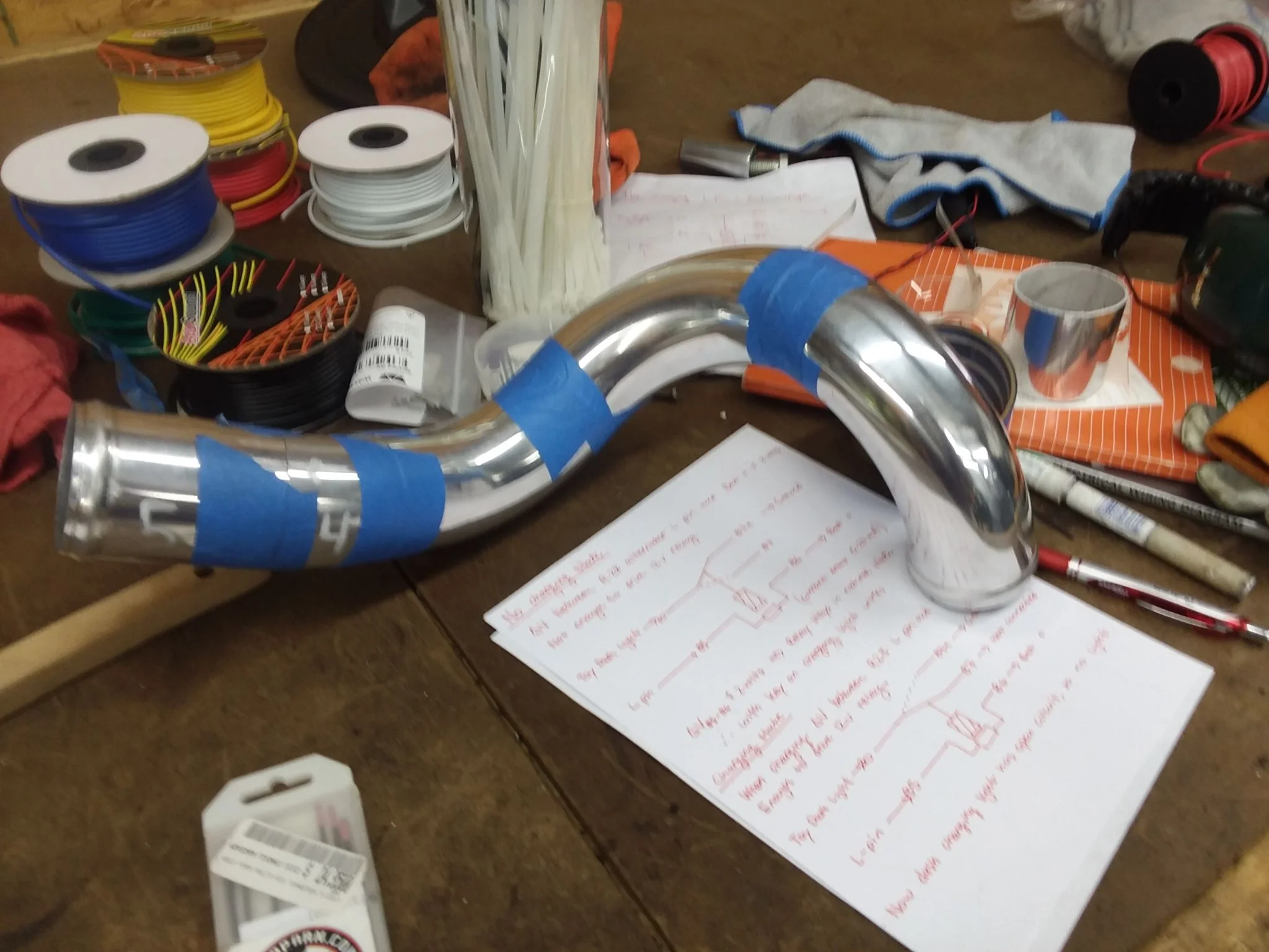
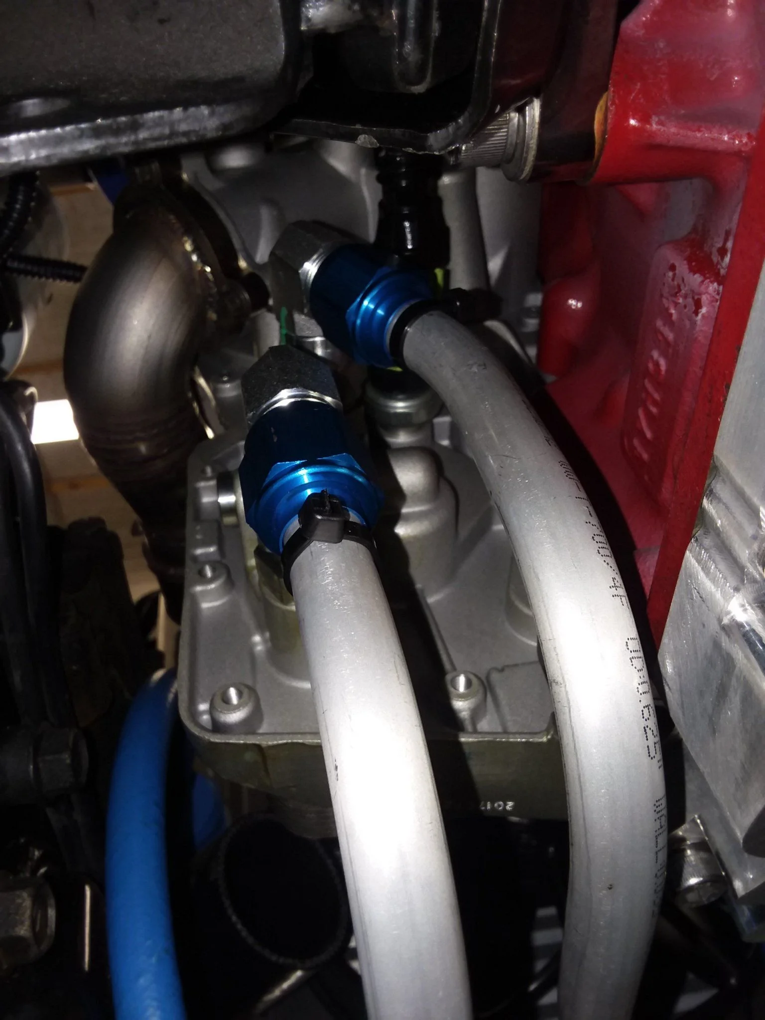
I have had several high pressure PS lines built using the OEM fittings. I just get everything set up how I need it (length, fitting orientation, etc.) and take it to the local hose shop and they crimp it all together.
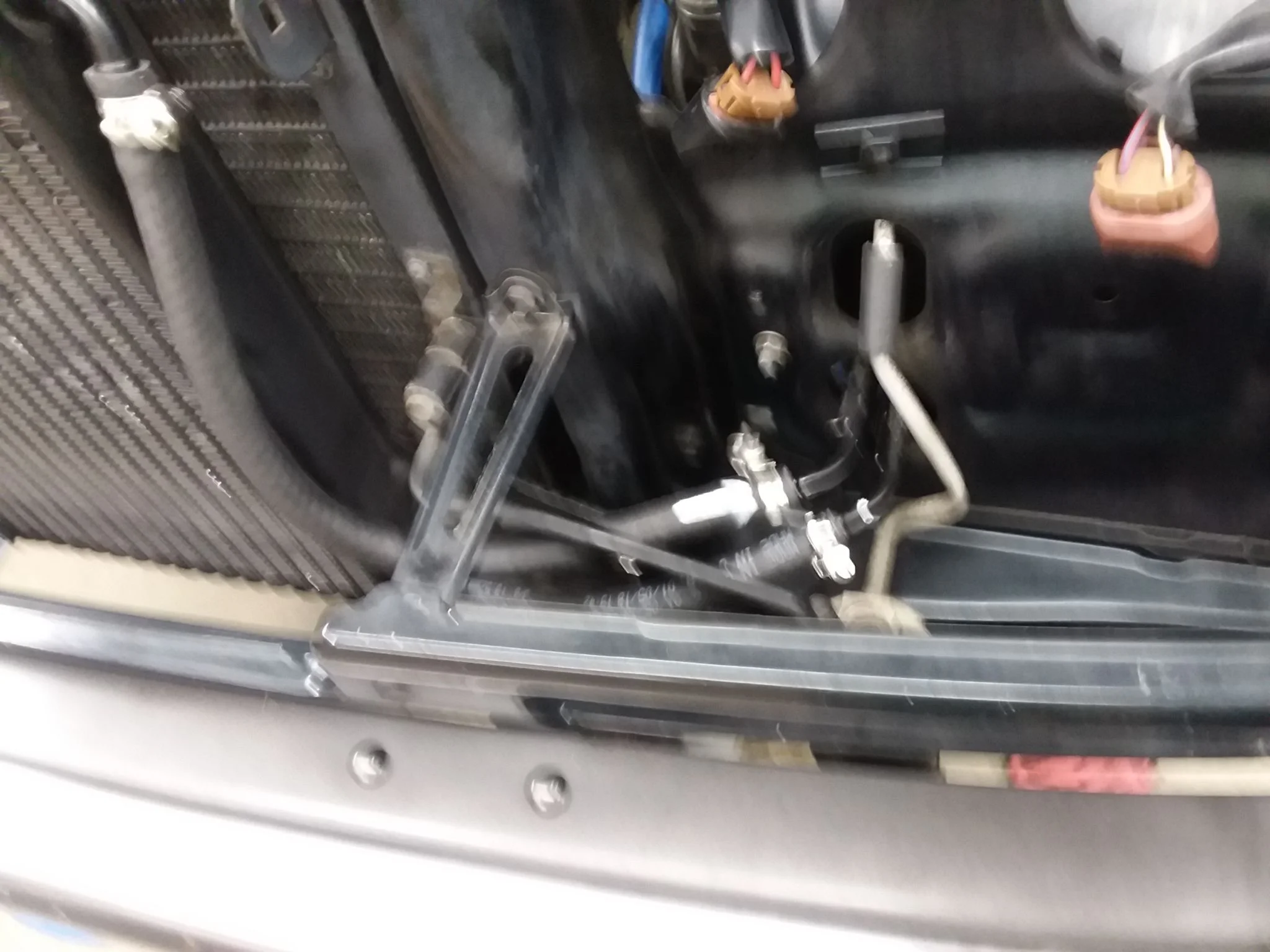
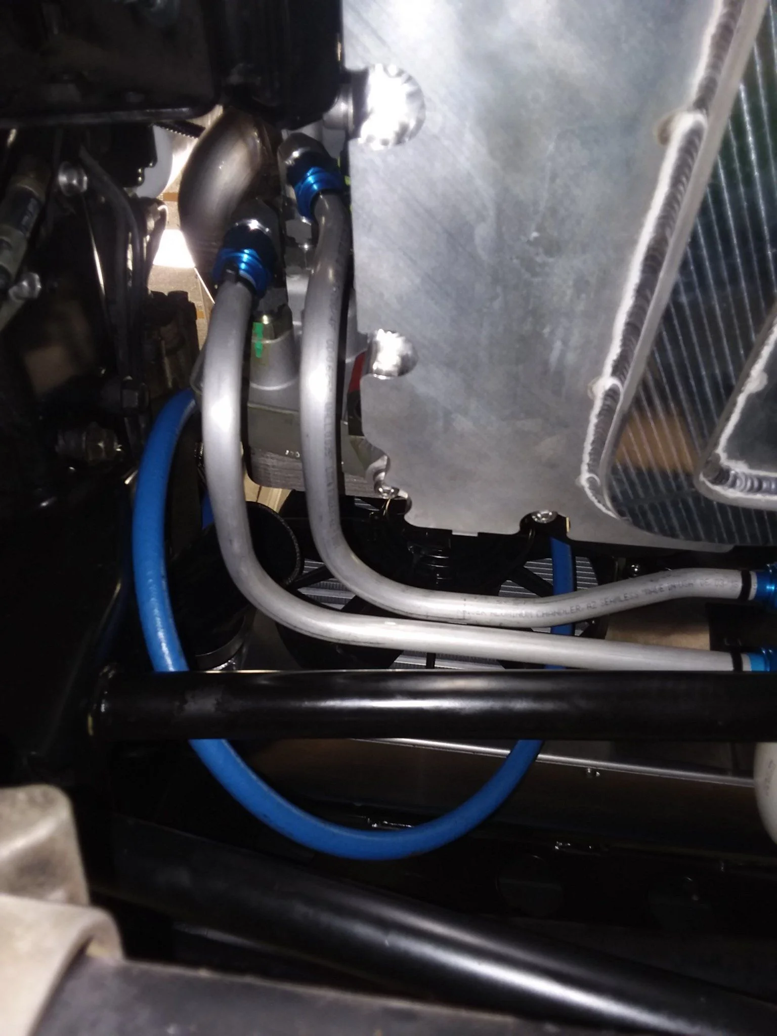
I hope to use a cooler like this on my 80 in the near future. It'll be mounted on the front of the cross member where the current paperclip cooler is. Also, wits' end sells a nice kit with a Derale cooler in it ready to rock (for stock 1FZ guys).
Well that's lame. I've always had mine done at Hose and Rubber, but I don't think they have a location very close to you. I suppose you could mark things up and send it to them? I'd bet you could find a hydraulic service shop near you that'd be willing to help you out though...I took my fittings into the local Parker Fitting Store and they said they could not help. Its gotta be Parker hose, parker fittings and parker crimp collars for them to do anything.
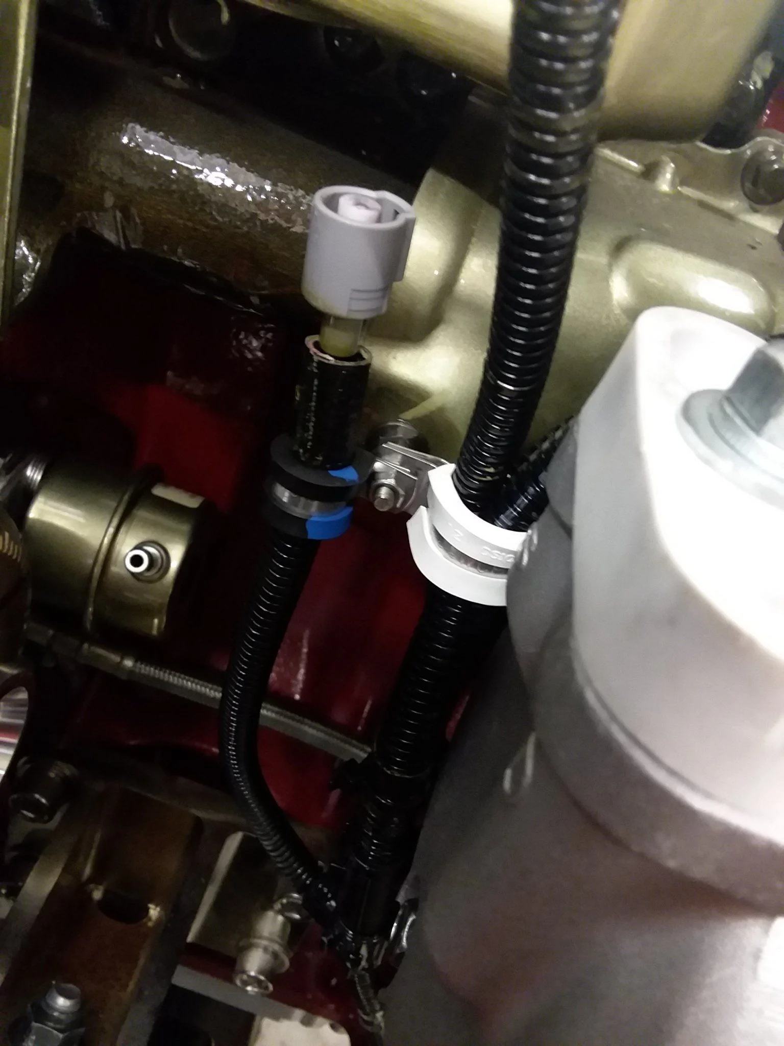
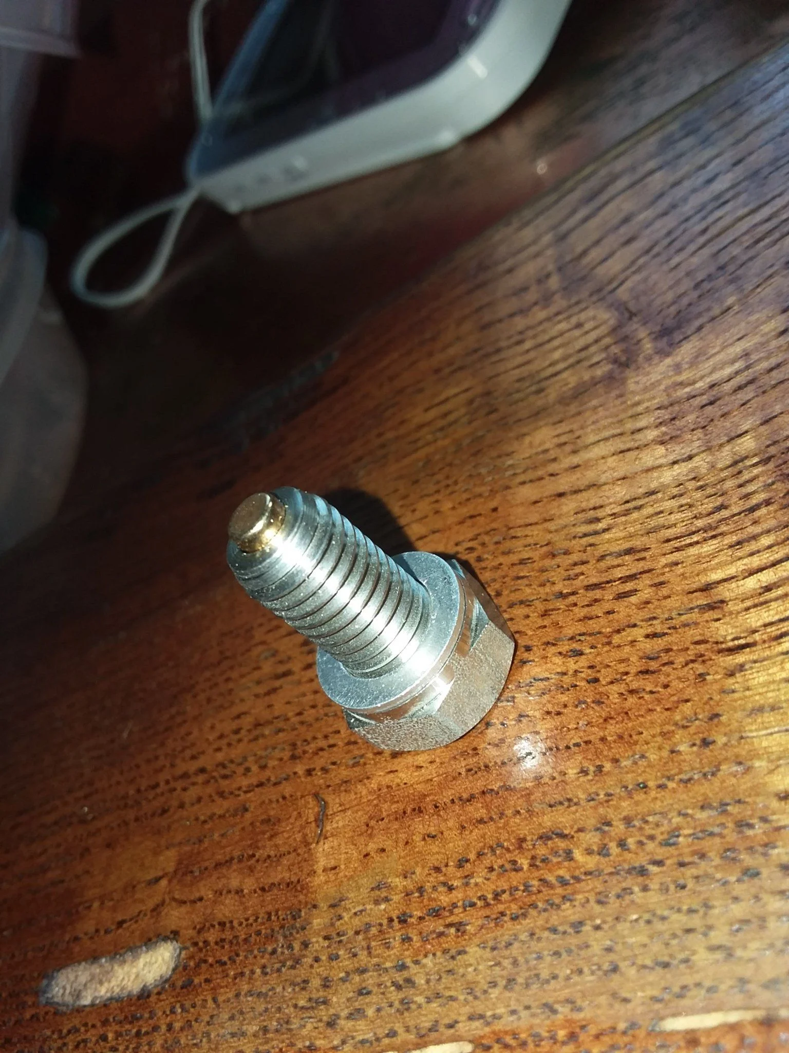
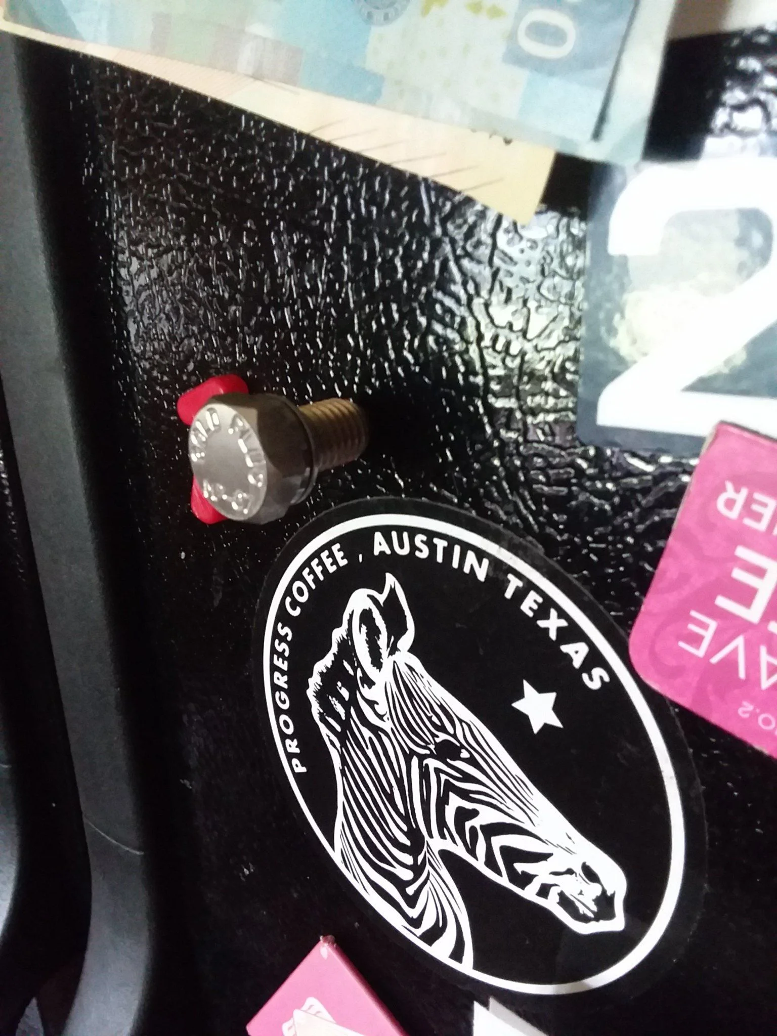
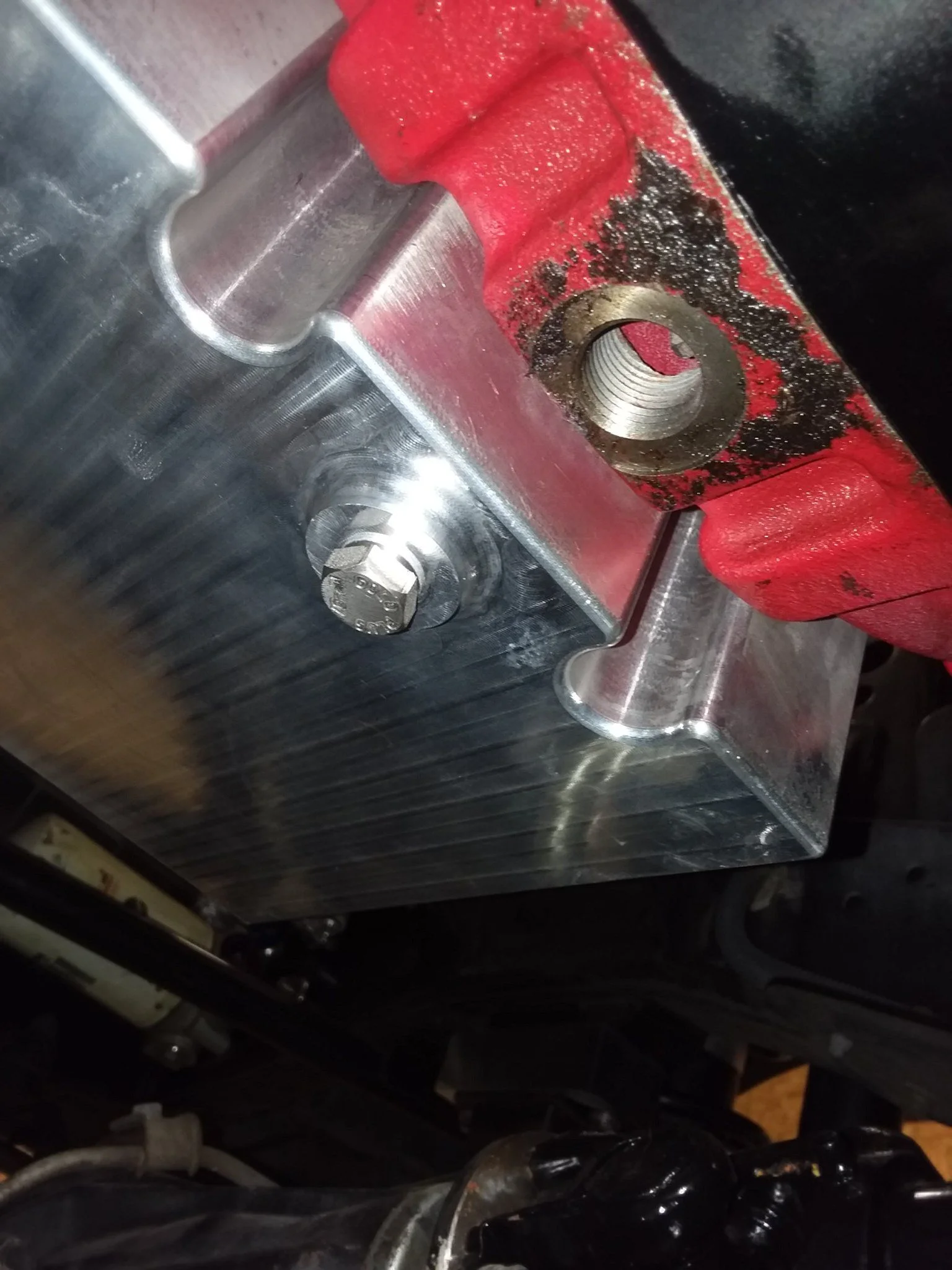
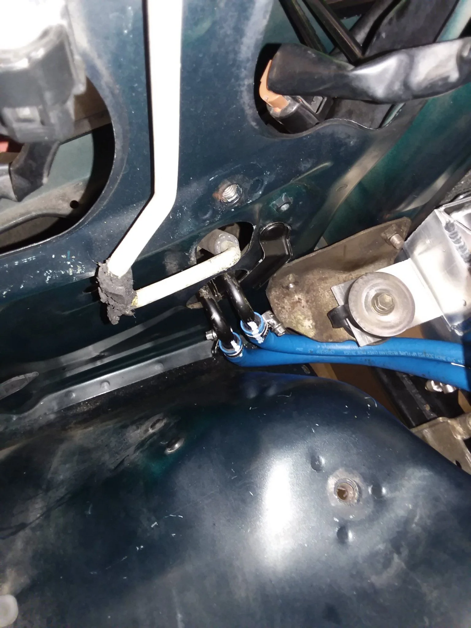
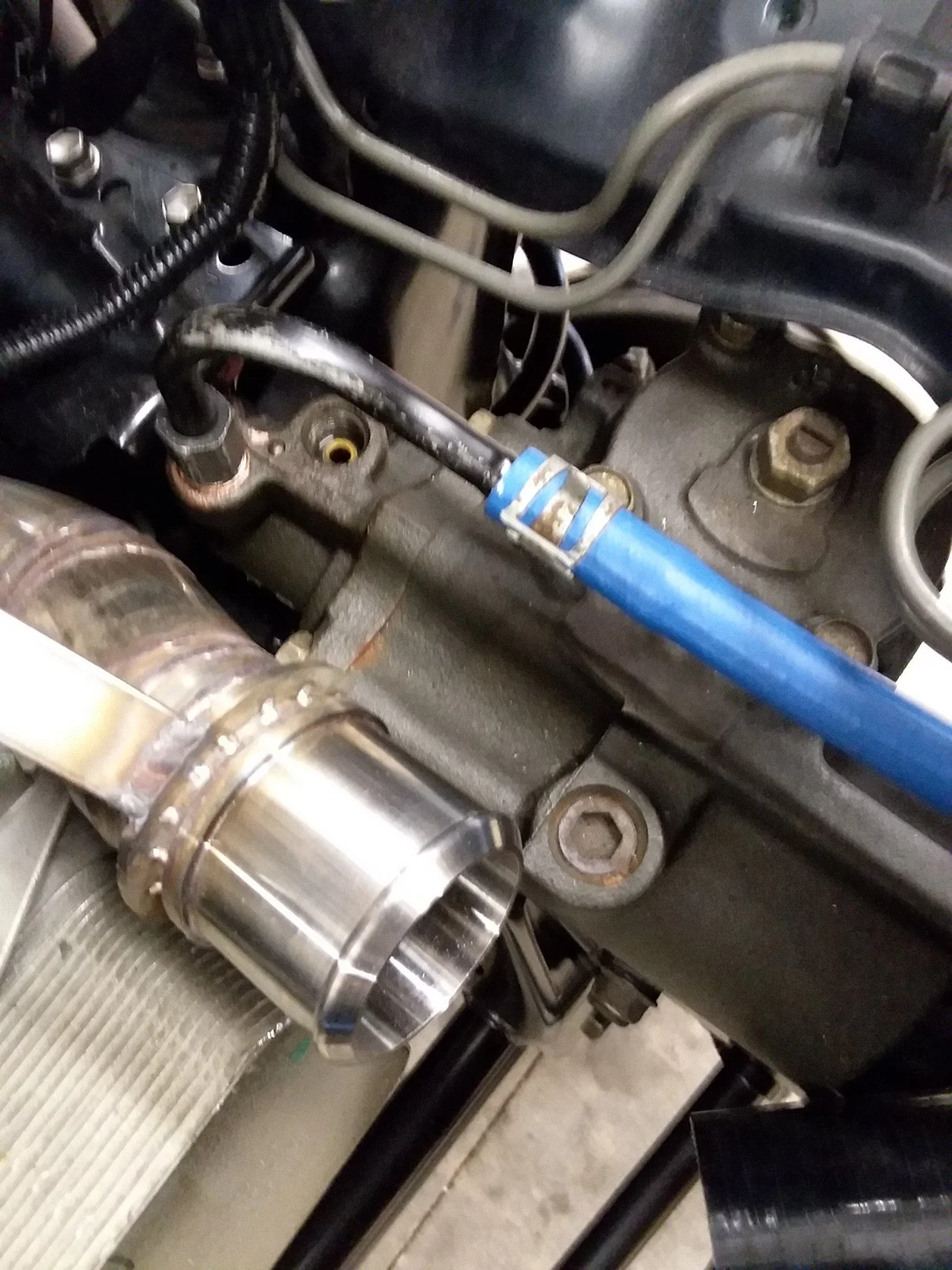
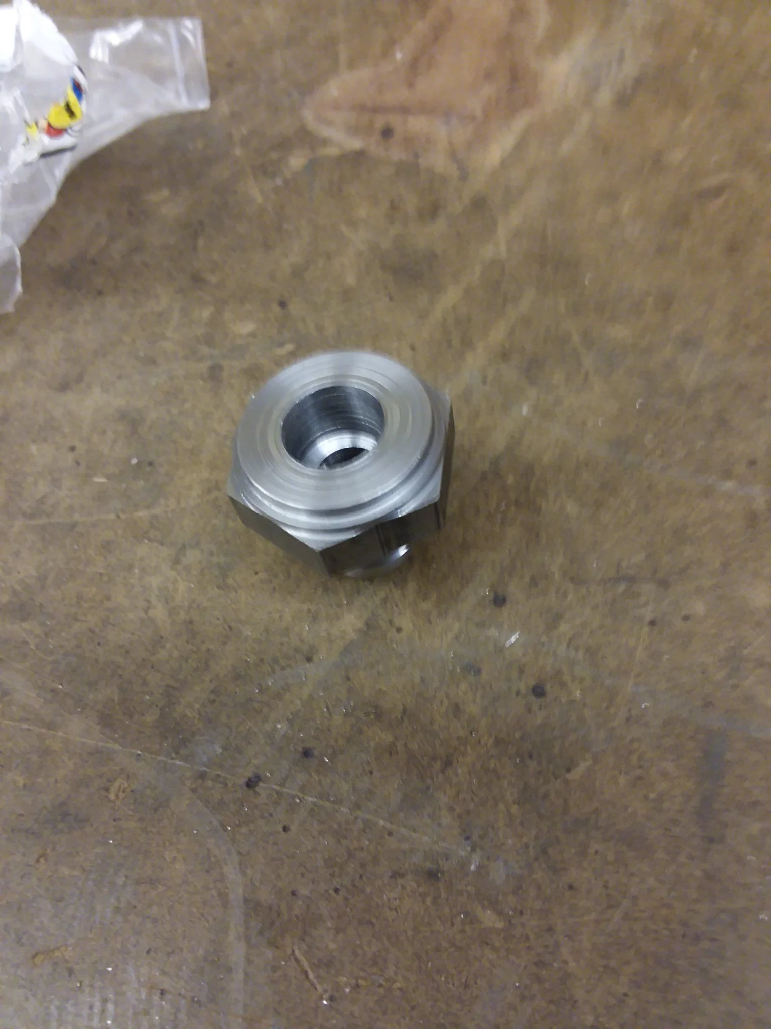
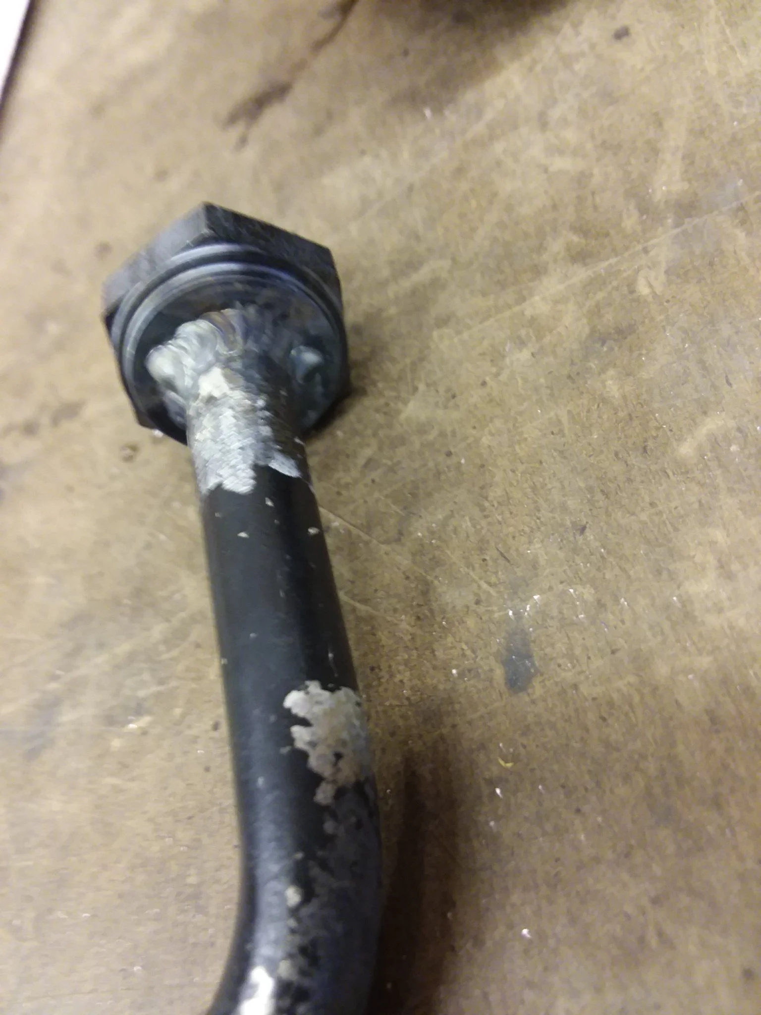
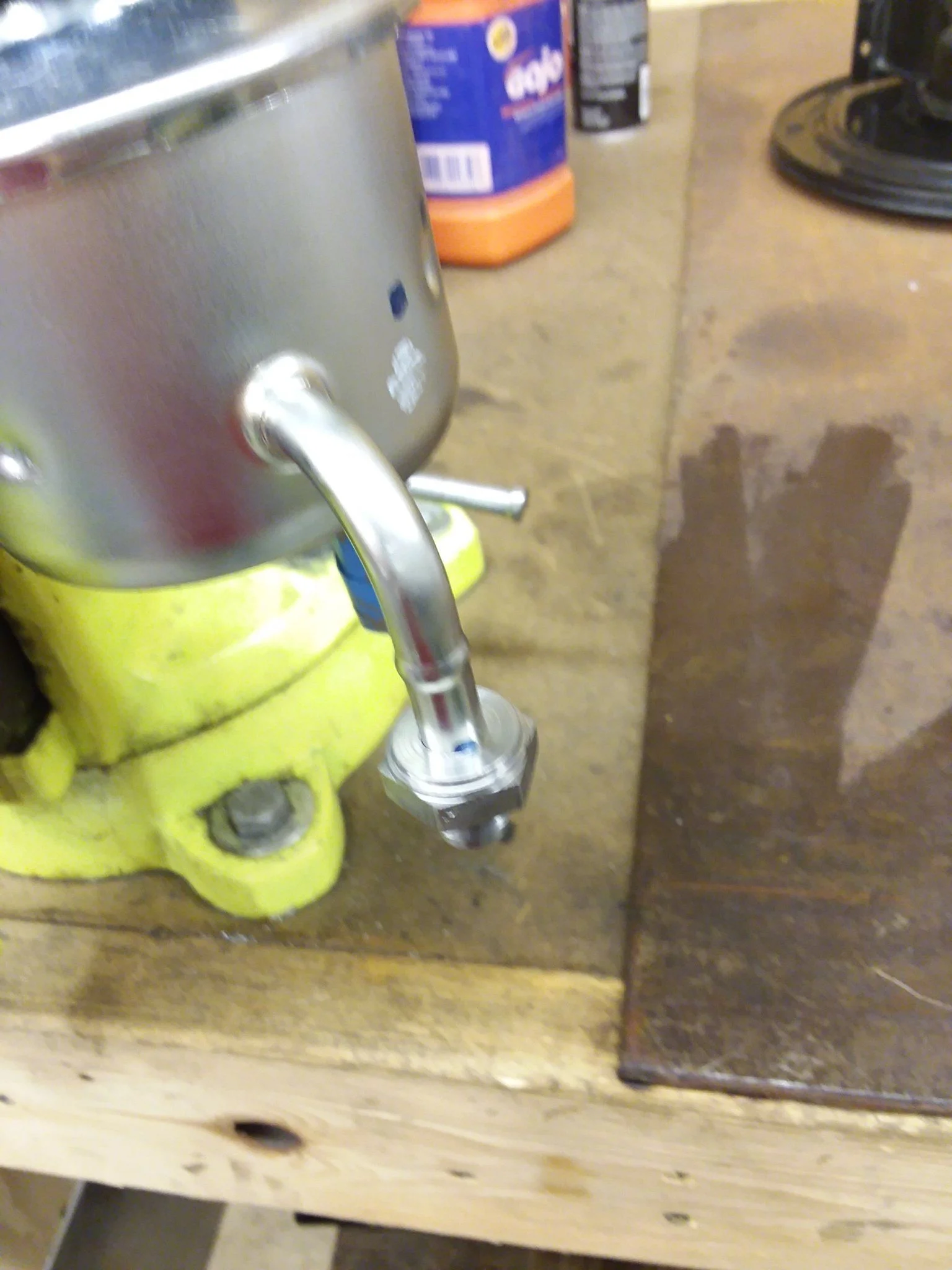
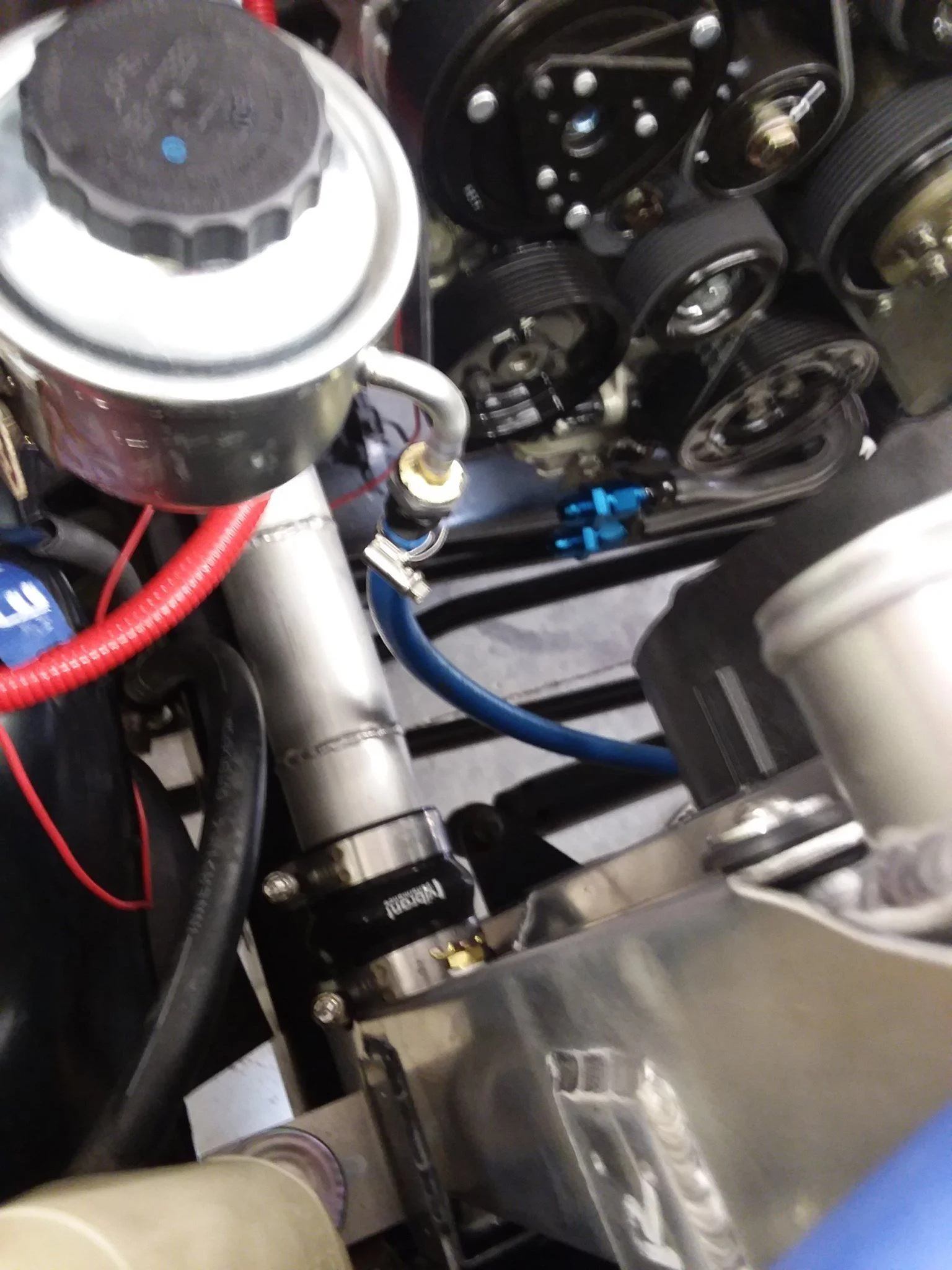
I've got a solution that I think will work well. Take a male -6AN fitting and weld it to the high pressure line on the steering box. The Cummins is ready to accept a M16x1.5 banjo fitting, get one of these with a -6AN fitting in it. Then get some hydraulic hose and the right hose ends. Sounded good in my mind anyways...Well that's lame. I've always had mine done at Hose and Rubber, but I don't think they have a location very close to you. I suppose you could mark things up and send it to them? I'd bet you could find a hydraulic service shop near you that'd be willing to help you out though...
Can you clarify what you mean by this?Ok unless you are at a load of 100% all the time this measuring is useless . There is no purpose in our application
Can you clarify what you mean by this?
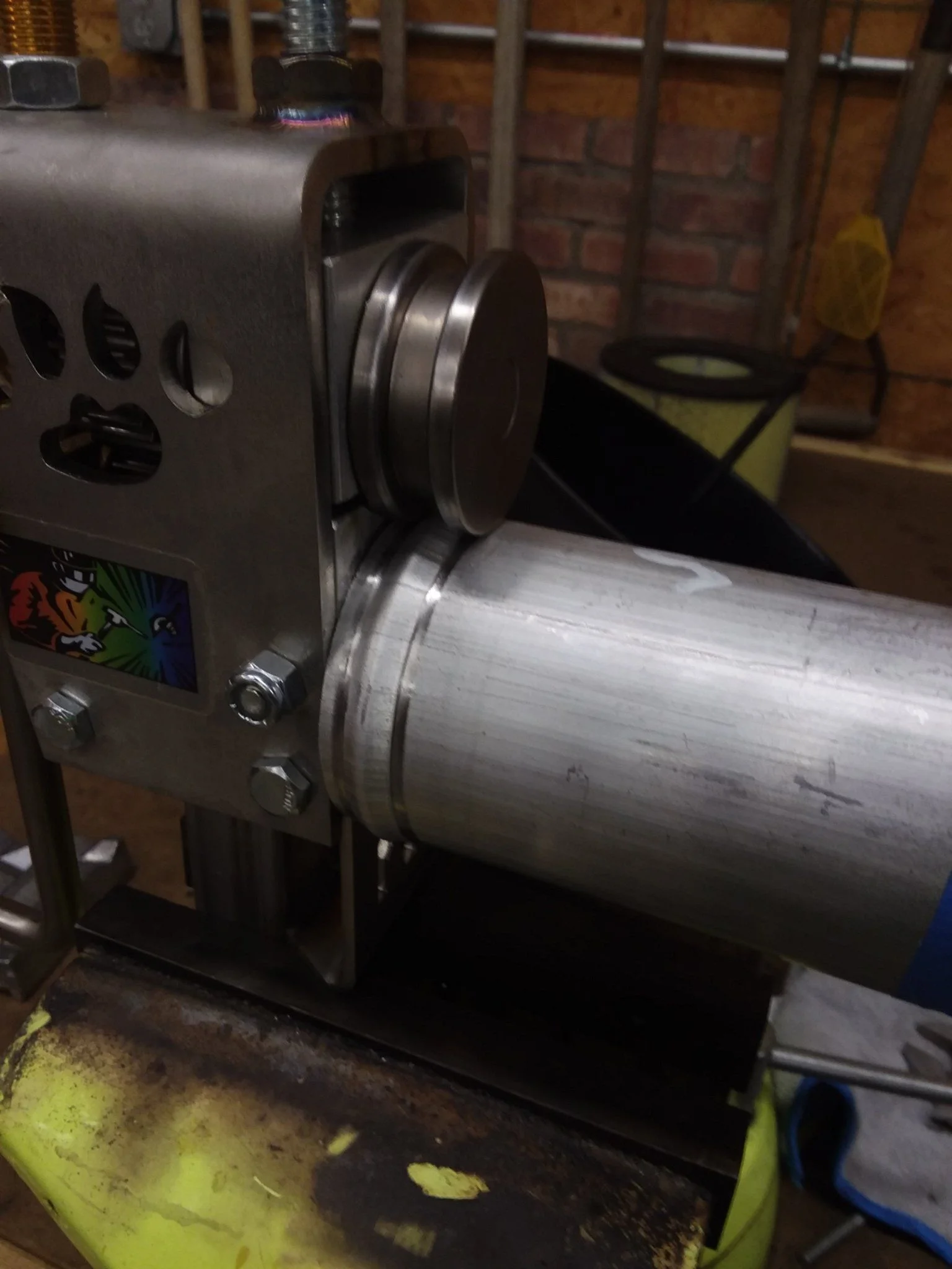
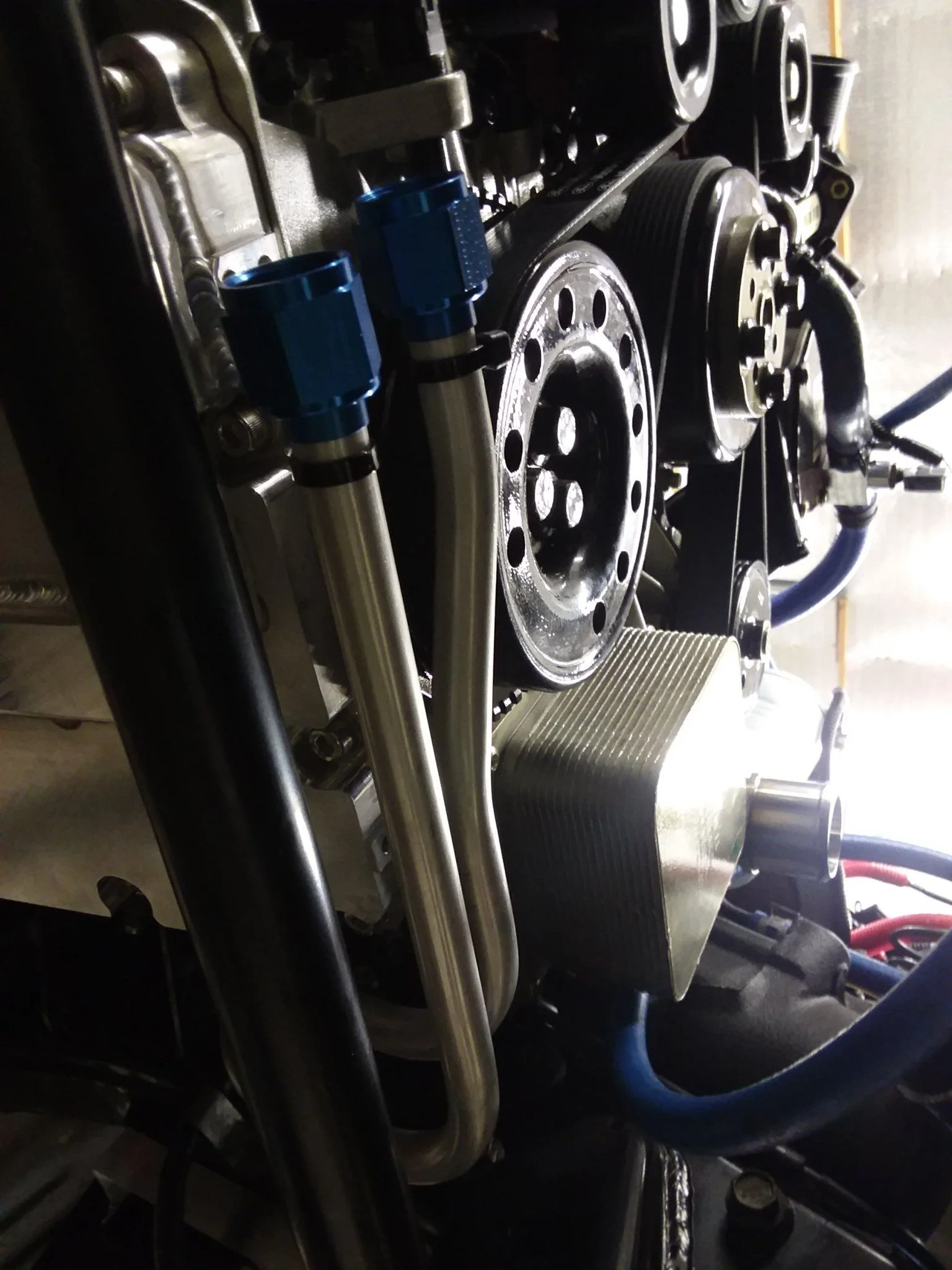
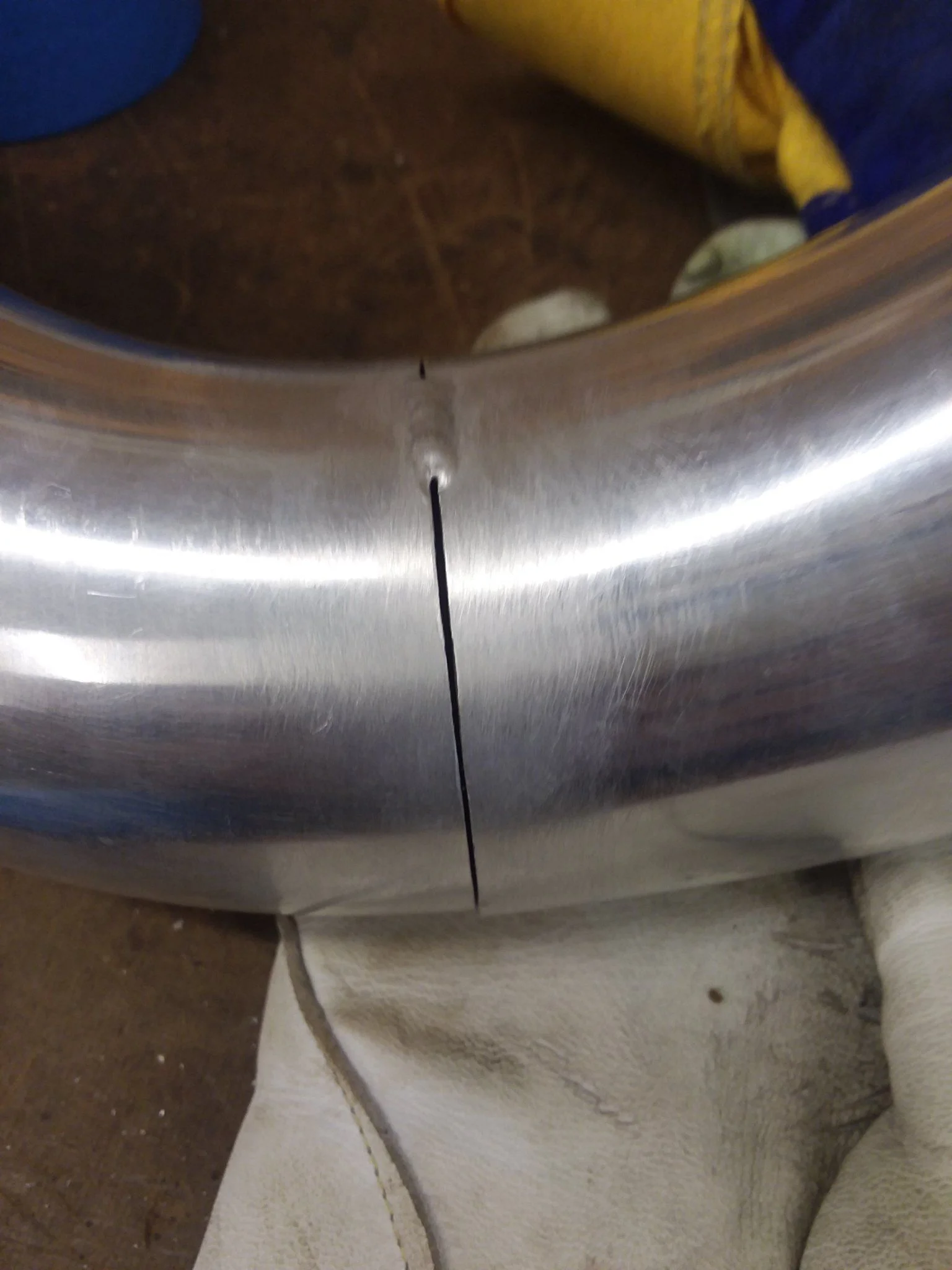
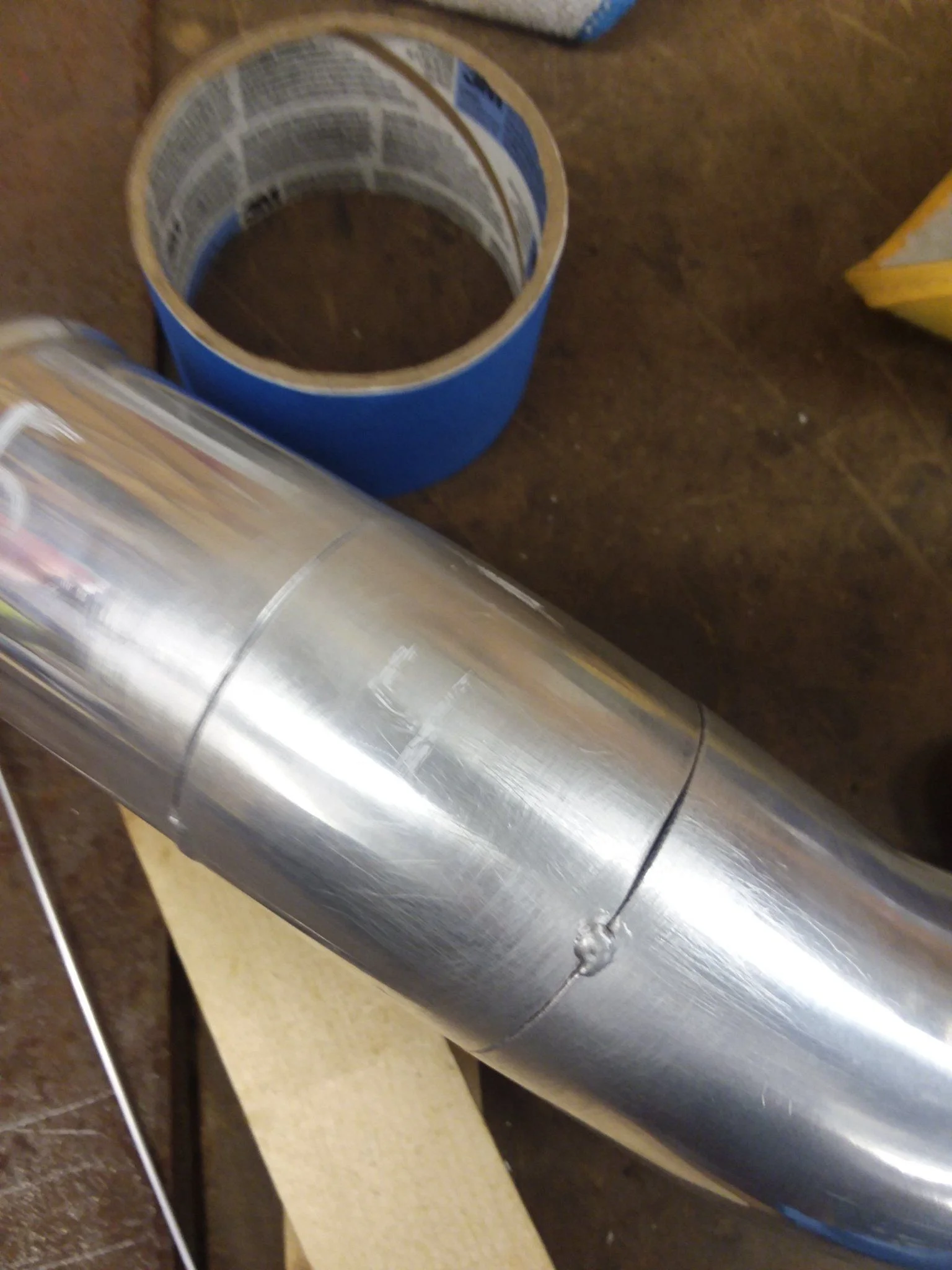
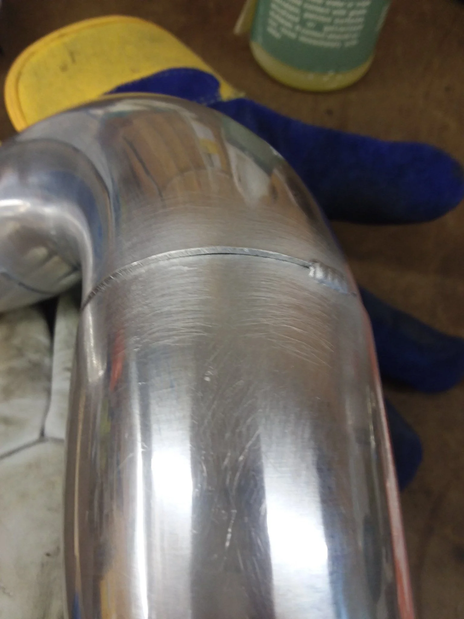
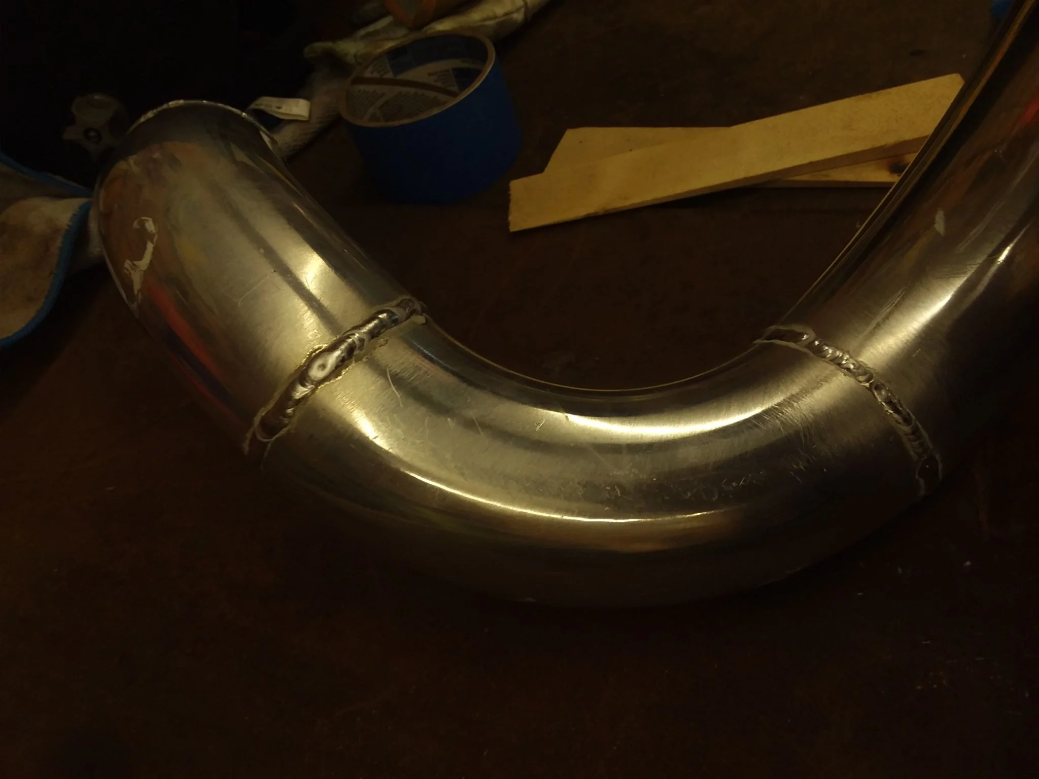
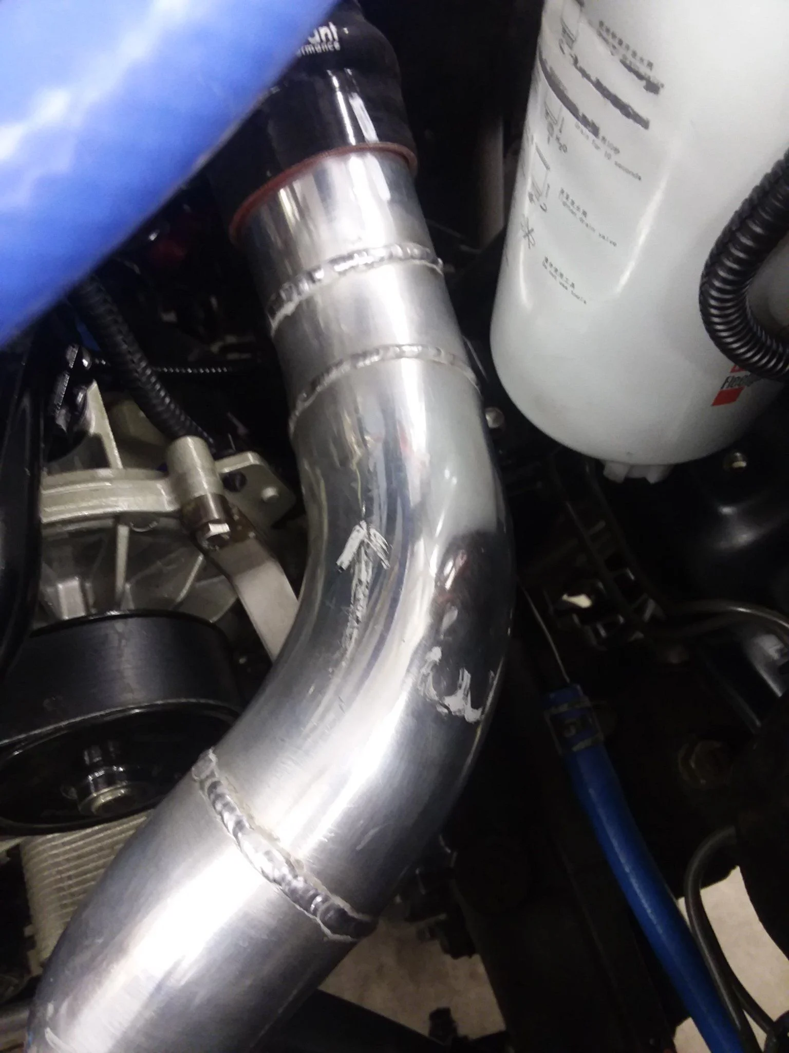
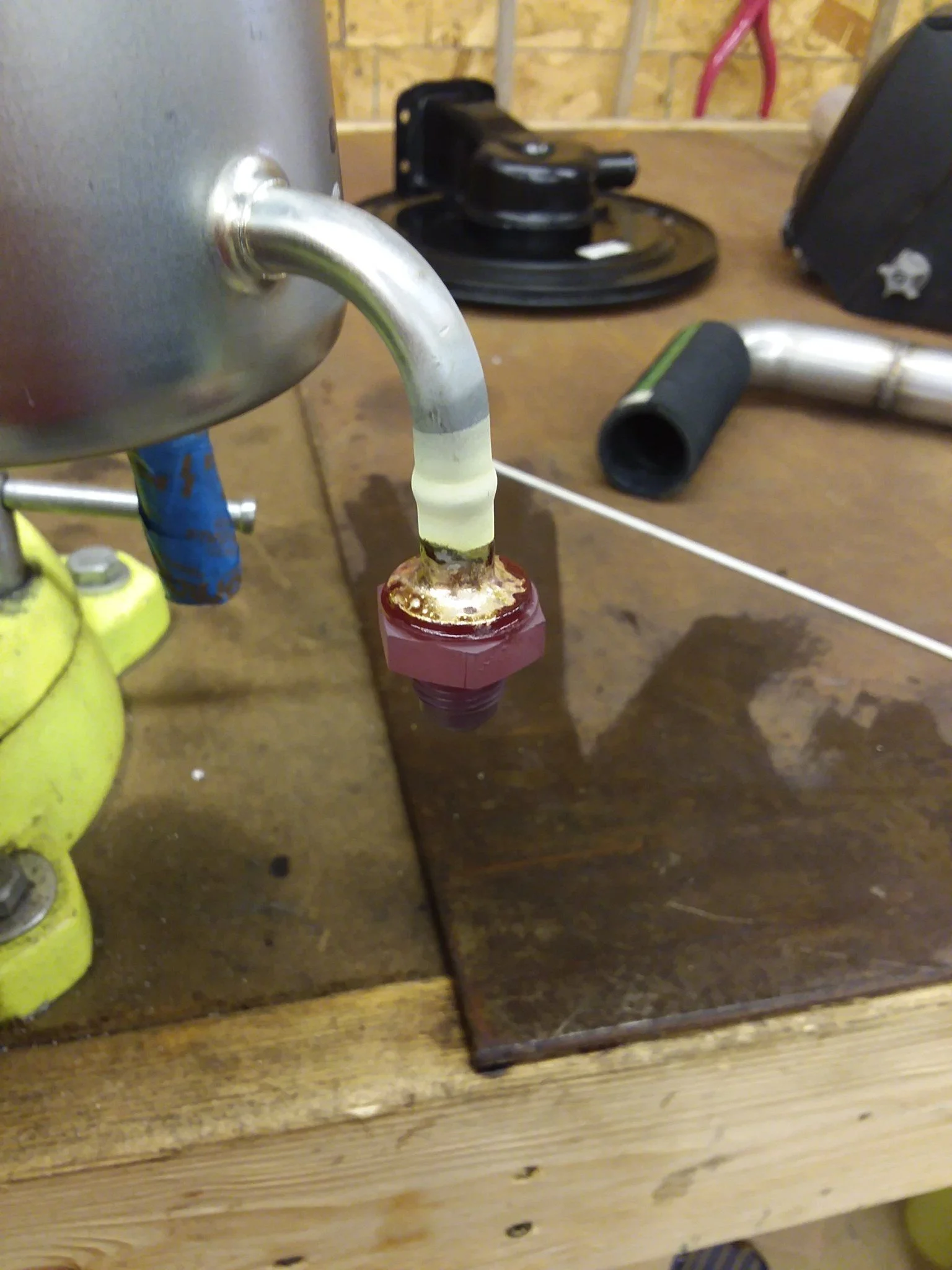
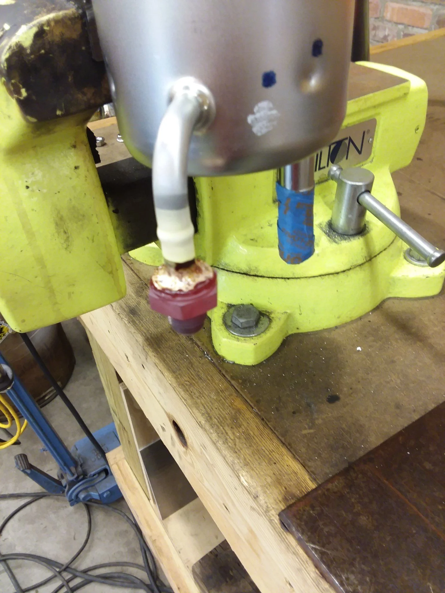
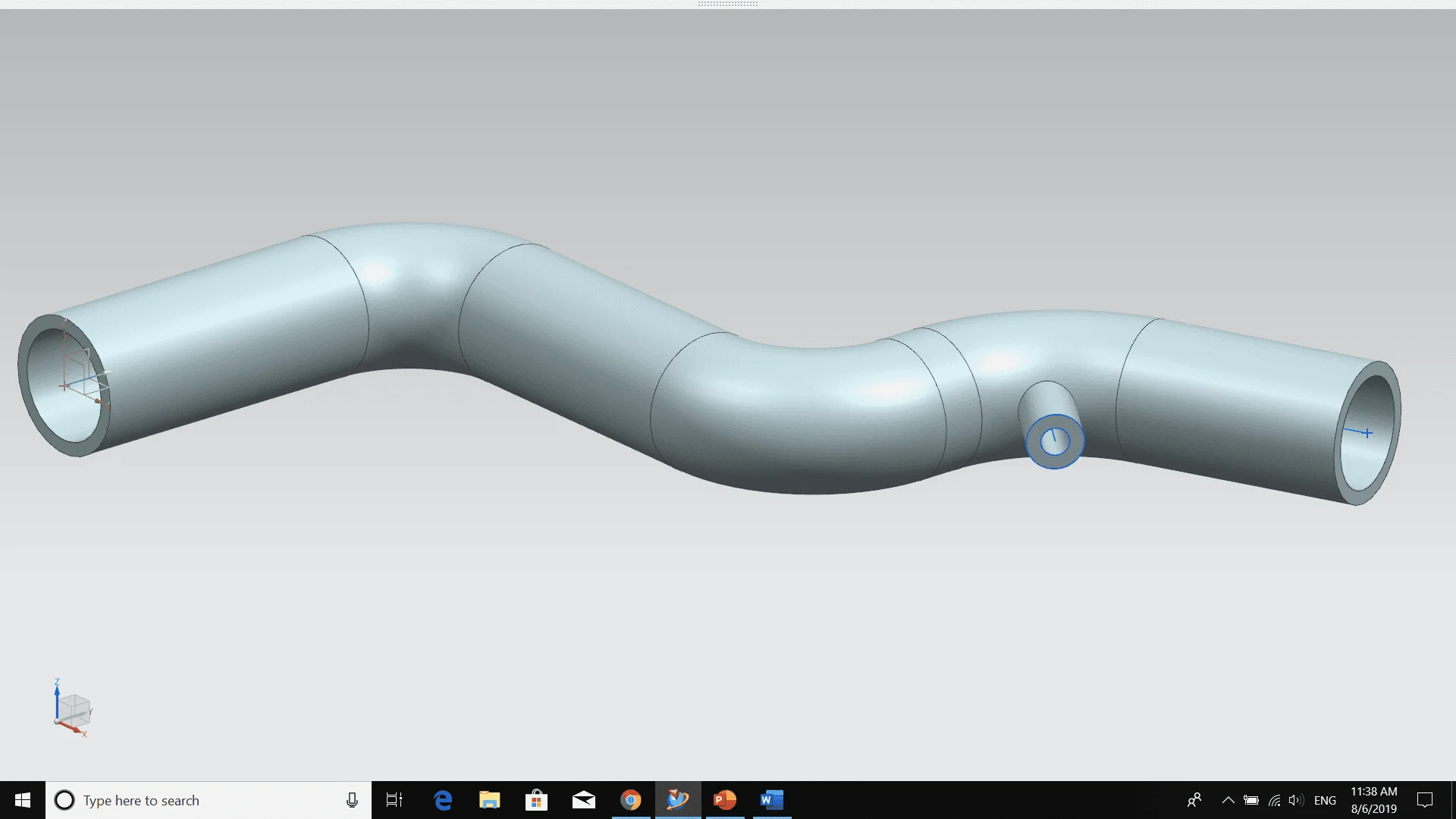
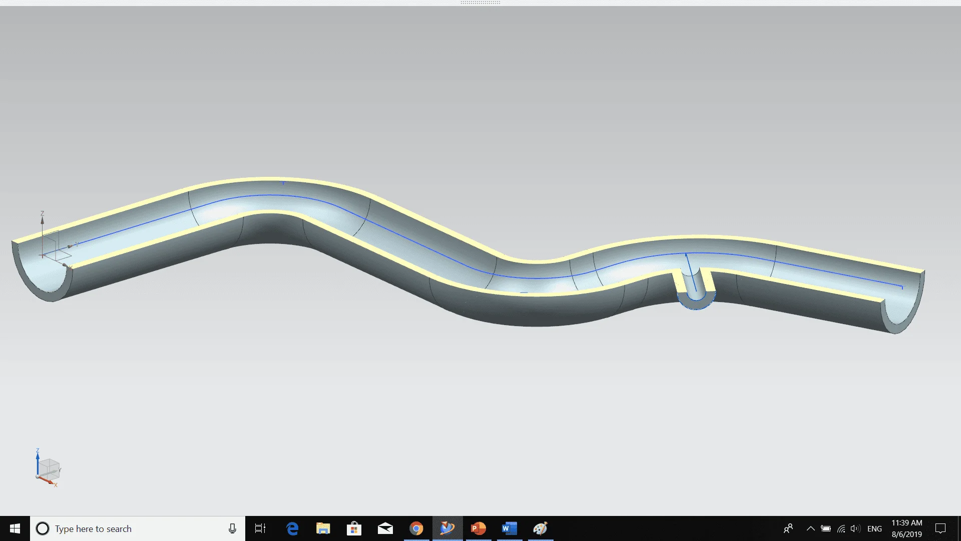
No back purge on this...Were you running a purge gas into the pipe while welding it?
So unless it is like a choo choo train hauling 70 full cars of rocks or something you will never get a measurable load on a vehicle long enough to get that measurement, it does not apply to cars
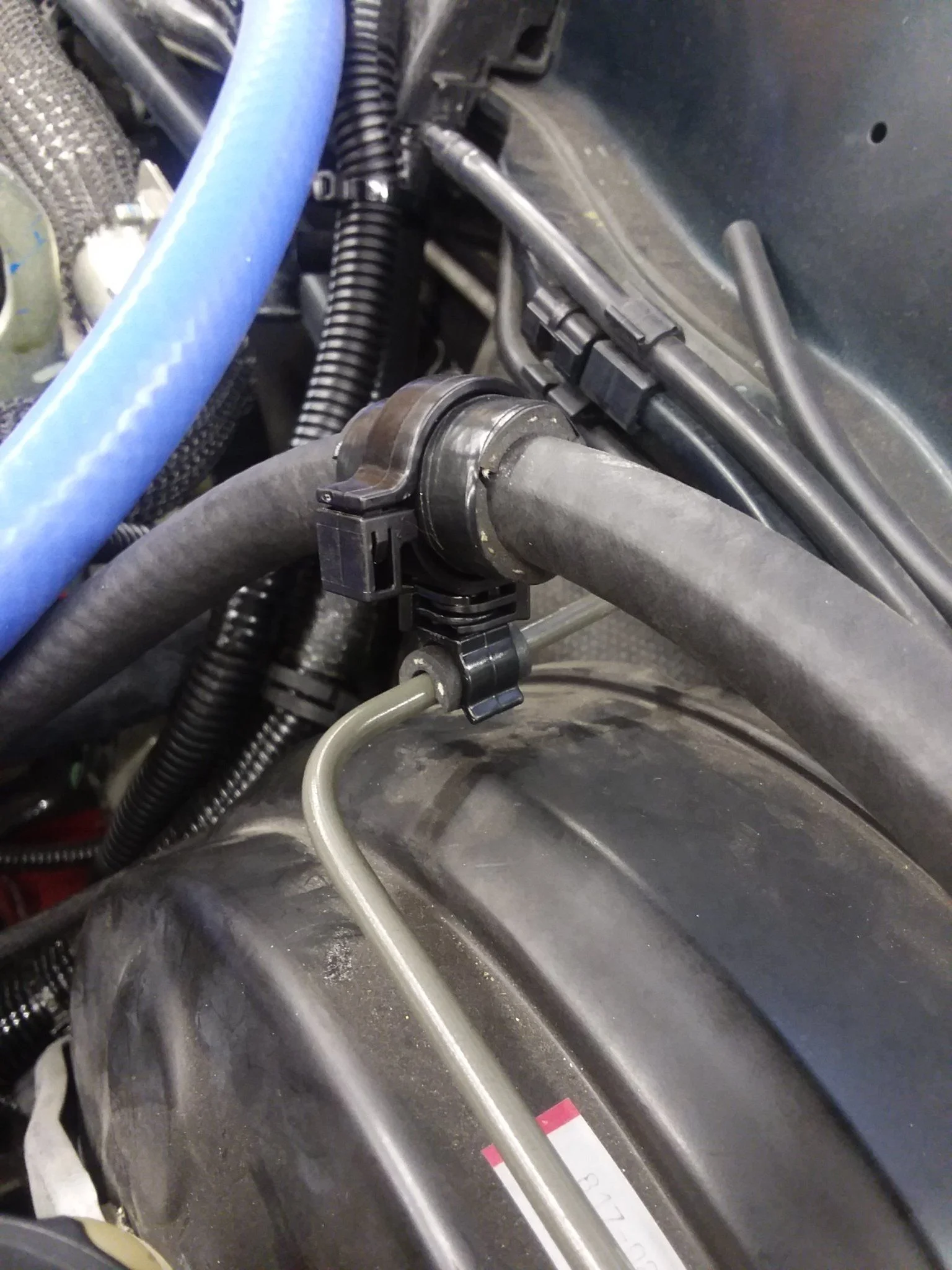
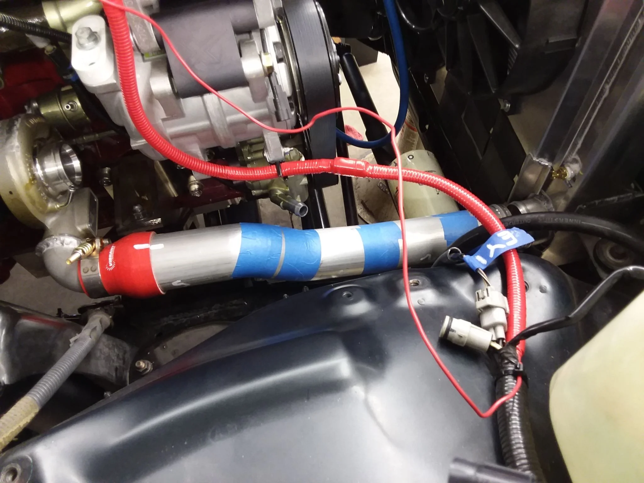
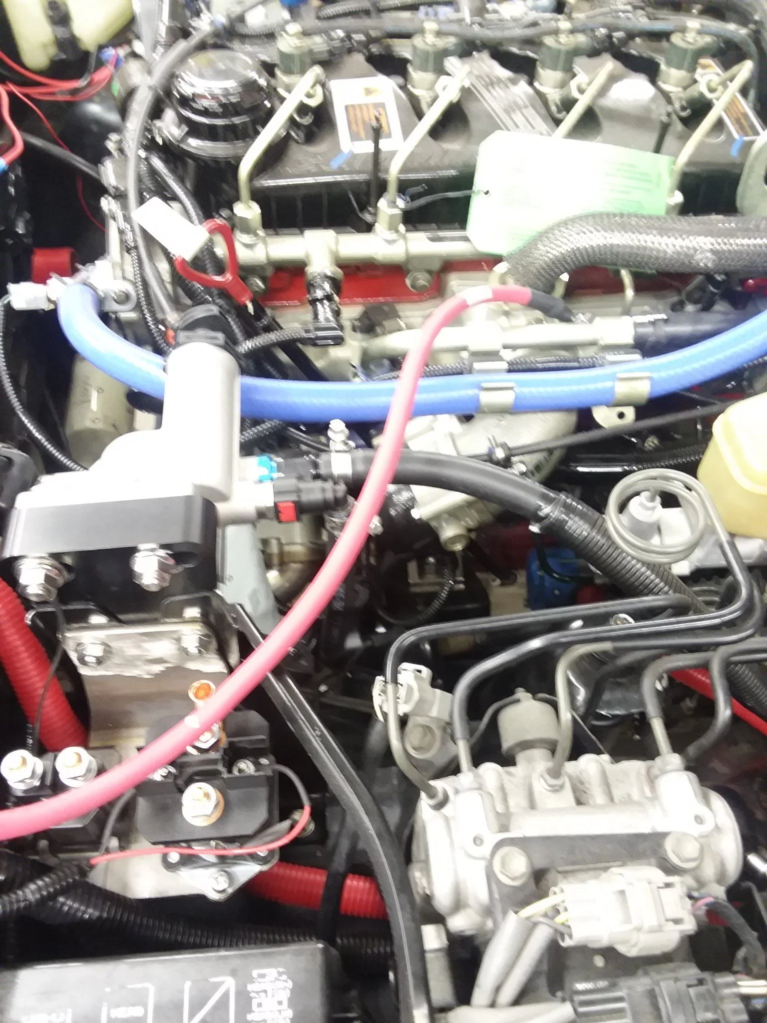
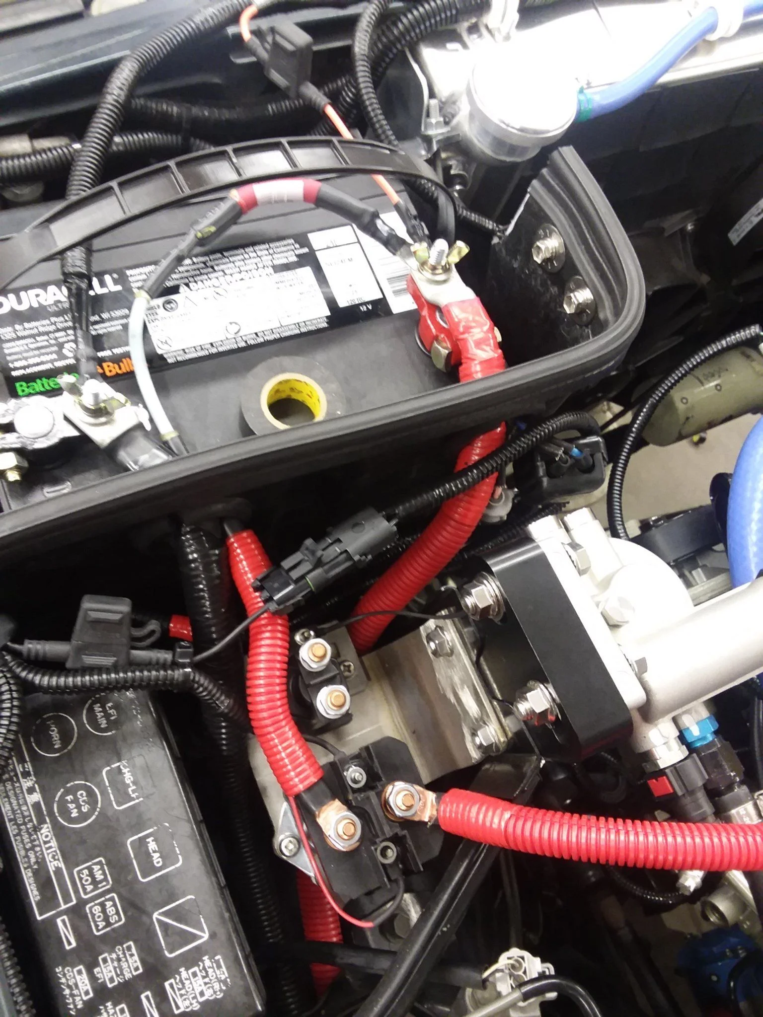
I make a strong effort to get atleast one thing done every day on the cruiser. Today it's something very simple. I have completed the intake grid heater wiring by modifying the Cummins supplied 4AWG cables to fit better in my chassis.
I got a couple of crimp on copper lugs and went to town, took all of 20 minutes.
Here is the cable as supplied from cummins. A little too long as you can see...
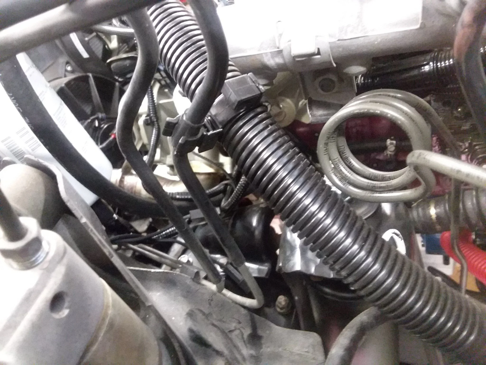
A quick trim, new lug and red split loom gives the finished product.
The other cable from cummins has a built in fusible link. Same plan of attack as above...
Now it should be able to fire right up on the cold mornings. Still dont have any info about block heaters, should have built a port into my oil sump for one. Do they even do that? My 6bt has one but I believe it sticks into the cooling jacket, makes a hell of a difference in February.
I must be missing something. I understand brake specific fuel consumption to be defined as the fuel consumption rate divided by shaft power produced. Thus, if your engine is running, then it is generating some amount of shaft power, and consuming some amount of fuel, regardless of load. I don't see how it would never apply. All power generation devices used for motive power, whether it be a 4-cycle gasoline engine, or a choo choo train engine, will have a brake specific fuel consumption surface. This surface is z-axis: BSFC, y-axis: power, and x-axis: RPM. A cross section in one direction gives you a BSFC curve vs RPM at a constant power level, and a cross section in another direction gives you a BSFC curve vs power at a constant RPM. I believe PurpleFJ62 slightly misspoke when he said BSFC curve, really he should have said BSFC surface; regardless of that specific thing he said, he was right, it always applies and it is a major criteria for design of an engine. Its also a handy tool for comparing different engines that could be potentially used in the same application, which is what PurpleFJ62 was implying.
For example, if you knew the BSFC surface of several engines that you are considering installing in a Land Cruiser, and you wanted to maximize fuel economy at 60 MPH on flat land, and knowing your gearing, drag, and rolling resistance, then you would be able to go to that BSFC surface and simply find the engine that has the lowest number given those inputs. In reality, it gets trickier choosing an engine because in the real world you'll be going up and down hills, up and down in speed, and not all engines have the same shaped surface. Basically you'll be traveling through many areas of that surface. It is then a more complex calculation to somehow average those BSFCs across a multitude of power and speed ranges. Some engines are very efficient at one point and fall off hard around that point, some engines are very flat and are fairly efficient everywhere. But not all engines are the same in this respect, some are very different than others.