Builds Here we go (FJ-40 getting a 3B/Turbo/H55f)...

This site may earn a commission from merchant affiliate
links, including eBay, Amazon, Skimlinks, and others.

So, here's Paul (Bad Mojo) sitting in the drivers seat with the 55 column bolted up with a steering wheel. You can see it's pretty close. So we've got a fix for that (that should even avoid cutting the column!!!) in the works. Pics of that when it's done...
steering 1.webp

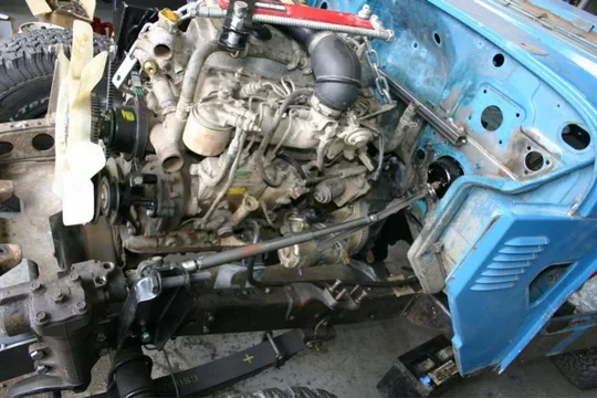
I attached a little piece of angle steel to the shaft of the 55 column to be able to mock this up. Just a look at the angle of the steering shaft from the 60 steering gearbox to the 55 column coming out of the firewall. Most workable. That shaft attached to the 60 steering gearbox is the shaft from the inside of the 60 series tilt column, BTW.
steering 2.webp

And here's a measurement from the firewall to the 60 series steering gearbox. I don't know if I can use the standard 60 series intermediate shaft (that telescopes with the cool rubber boot) or if I'll have to have something custom made or what.
steering 3.webp
steering 1.webp
steering 2.webp
steering 3.webp
 
Here's mocking up where I'll mount the Racor fuel filter (with heater and water detector!)
fuel filter.webp

Here's the cobra adapter on the front of the turbo----and how it hits the hood. I'm going to have to think about how to get the intake from the front of the turbo (3" diameter) across the engine and over to where I plan to mount the Donaldson air filter under the hood. I'll probably see if I can't get some tubing bent to fit real tight and see how that looks.
intake 1.webp

And here's a quick snap of the right side of the motor. You can see how much room I gained around the firewall by moving the motor 2-3" forward of the "stock" position. There's TONS of room to route the exhaust out of there.
motor .webp
fuel filter.webp
intake 1.webp
motor .webp
 
Since I had the help, we tacked up the back part of the Metal Tech Jackson Cage for the 40.
mt cage 1.webp

Then I had Paul sit in the driver's seat to get a good picture of how close the MT cage came to his head. He's tall (6'2" maybe?).
mt cage 2.webp

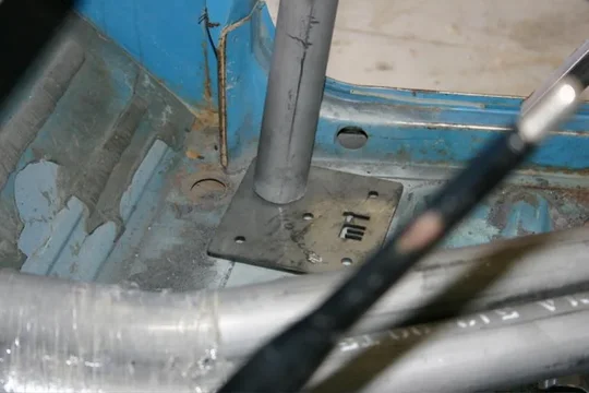
Here's a pic of the underside on the right, showing the cage plate bolted to the topside plate, just so I can start figuring out how I'm going to tie the cage into the frame....
mt cage 3.webp
mt cage 1.webp
mt cage 2.webp
mt cage 3.webp
 
After pappy got his MT Jackson cage pre-welded, I was a bit worried that the cage would be too "short" in our truck. I'm sure the pre-welded models are a bit smaller just to make sure they fit in all the trucks, but I want to save every inch possible inside, AND I'd already done the bodywork on the floor to make room for the MT cage plates.

Luckily, the cage kits come with the front hoops still long, so no worries at all.

But here's the plate (and the front hoop help up on it).
mt cage 4.webp

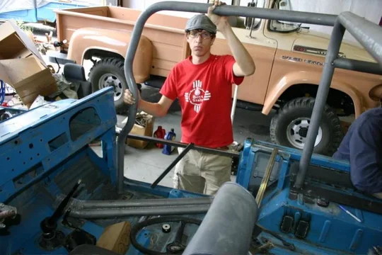
And Paul holding the front hoop up for me to get a pic of it's fitment...
mt cage 5.webp

And here's the extra that I can trim to make it fit as tight to the dash as possible.
mt cage 6.webp

I'm very pleased with the MT cage. I ran out of shielding gas in the welder, so I didn't tack anything more than the rear hoop and bars, but no worries.

That's it for now. We've got the 55 column out for some "work" to make it "right" for the 40, and I'm pretty busy with work (and a trip to the Washington coast with the chica) for the rest of the month, but first week of September.... Dad is probably busy at home grinding down the welds on the tub, and he's the one actually dealing with the 55 column work, and some other odds and ends right now.

To say that I'm pleased is an understatement. I do need to lower the motor and transmission mounts just about 1/2", and I need to finish the body work on the floor of the tub (just the bed, and I've got a donor tub lined up I think), but with any luck, the tub will be blasted and epoxy primed by the end of September (along with all the other body parts) and I'm hoping to drive it like that a bit just to make sure I don't need to make any changes before I commit to painting it....

Dan
mt cage 4.webp
mt cage 5.webp
mt cage 6.webp
 
OK, just got a day and a half to tinker with the 40, so...

We removed the tub from the frame again.

Then I moved the transmission crossmember mounts down 10mm to end up with just a small gap between the H55f and the tub. Fingers crossed...

I don't think it hangs down too far below the frame. I'll either use an IPOR skid plate or make my own to cover all this up anyhow...
crossmember.webp

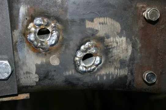
I also sleeved the bolt holes for the shock tower and welded the inside frame plate for the PS gearbox on.
sleeve.webp
sleeve 2.webp
sleeve.webp
sleeve 2.webp
crossmember.webp
 
Since I had lowered the crossmember, I decided I should stop procrastinating and get to fabbing up the motor mounts. It really wasn't as bad or hard of a job as I was expecting. I took maybe 5 hours to them them pretty much done.

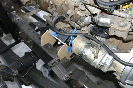
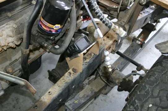
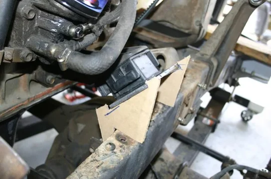
I'll let the pictures do the talking, but I used 1/4" sheet steel, cut with the plasma cutter for them. But I started with some cardboard...

mount mockup 3.webp

mount mockup 2.webp

mount mockup 1.webp
mount mockup 1.webp
mount mockup 2.webp
mount mockup 3.webp
 
Then I tacked them into place...

The right side...
motor mount 1.webp

And the left side. I know that the stock radiator core support rod won't stay in that form (it hits the steering shaft), but I went ahead and put a hole in anyway just to make it work if I wanted to. If you were keeping the original steering gearbox then this would work beautifully.
motor mount 2.webp
motor mount 3.webp
motor mount 1.webp
motor mount 2.webp
motor mount 3.webp
 
And here's a final three for the evening...

One of the mounts with the welds finished.
motor mount 4.webp

An overview of the engine in the frame.
motor mount 5.webp

And here's the front. It is too close for my taste to the fan shroud, so I will actually cut the tack welds off the motor mounts/frame and will cut some 1/4" to act as a spacer (will also add some strength, and I like that too).
motor mount 6.webp

That's it until next week! Those motor mounts will work well I think. I'm much happier with the angle the engine sits now, and the motor mounts are compressed perfectly with these. I'll probably gusset them a bit, and there's the already mentioned spacer/stiffener between the top of the frame and the motor mounts, but they're pretty much checked off the list!

I somehow got the wrong stuff from 4 wheel auto for the steering. Apparently I got a 70 series tie rod (that goes between the two knuckles) and a tie rod end for the left side of that, instead of the 60/70 series TRE that mates to the pitman arm, or the late 40 series tie rod end that will mate to the existing 40 tie rod (the one between the knuckles). Not too sure what to do about that. I'm not sure what it would cost to send it back to Edmonton versus just cajoling CDan into ordering what I need (or some other supplier).

Dan
motor mount 4.webp
motor mount 5.webp
motor mount 6.webp
 
Looks like you are making progress since the last time I saw it last. I am really liking the power steering set up. I wonder why. It seems to be coming along pretty well. As always if you need any help let me know. I am going to send you a PM in just a sec regarding parts that I owe you. Can't wait to see it put all back together.
 
I've been getting more done on it too.

I'll try to post an update in a couple of days. Ali and I went wheeling/camping last week and I toasted the fan in the faux-lux. After reminding myself how stressful it is to be caught in traffic without a fan, I decided to tackle that (and a whole other electrical rewiring/bracketry/misc project) today. Tomorrow I'm off to explore Chaco Canyon with the chica, and when I get back I should have time to post an update. If I can set the tub back on this week I might be able to finish the 60 PS swap--maybe.

I'll get a response to your PM in the morning.

Dan
 
Why haven't I updated this?

For one, I added 1/4" plates between the frame and the motor mounts, to both raise the motor a touch, and to move the mounts in a touch.
mount 1.webp

That centered the fan in the shroud nicely...
mount 2.webp

And here's the isolator on the right side.
mount 3.webp
mount 1.webp
mount 2.webp
mount 3.webp
 
After test fitting the tub--again--I was happy with how it sat. So I finished the welds off and really attached them to the frame.

The transmission crossmember mount...
mount 4.webp

The right side motor mount. The cutout is to clear the bracket for the brake line.
mount 5.webp

Now here's where it gets a little weird. When I first set the motor into the mounts, it site nice and straight. Both motor mounts look great, and it is exactly where I want it. No complaints then--at all. But, after sitting for about a week, the left side motor mount sort of slides down. The pic shows it as best I can. Only the left side isolator does this. I will probably try swapping the isolators from left to right, just to see if it follows the rubber isolator, or is a bigger problem. I certainly welded a bit with them bolted on there, so I very well may have gotten the rubber too hot or something. I also wonder if I started the engine and let it shake for a bit if it would level itself out.
mount 6.webp

Even with the "sliding" isolator, the motor sits just fine, doesn't get to close to anything, and isn't in any danger of hitting anything even if the motor makes some torque (which would lift the left side anyhow). I just imagine that "sliding" isolator wearing out really quickly like that.

Anyone ever seen this? Ever fixed it?
mount 4.webp
mount 5.webp
mount 6.webp
 
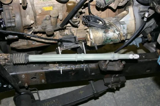
I won't get too much into the steering setup here, but when it's all said and done I will do a complete write up on just the 60 series PS conversion I did in the 40 section. That said, you can see the trick we used here to make it all work in these pictures. The parts are basically an FJ-55 steering column, and an FJ-62 steering shaft.
steering 1.webp

I did have to lengthen the FJ-62 steering shaft. you can see my cut and splice pretty clearly here (just look at my not-as-nice-as-Toyota's welds). I even managed to keep it straight within about 1mm, not bad for my primitive means.
steering 2.webp
steering 3.webp

I still need to figure out what I'm going to do to connect the pitman arm to the knuckles. I think I'll be using a stock 60 series pitman arm tie rod, a custom tube and a TRE that mates to the stock FJ-40 TRE on the right side knuckle.

I have gotten a lot more done, but apparently I didn't take pictures of it. :hillbilly: Among other things, I made a HUGE shelf for the shop. I reduced the pile of FJ-40 parts into a neatly stacked and labelled section of the shelf. Hopefully I get some pictures of that stuff when I get home next.
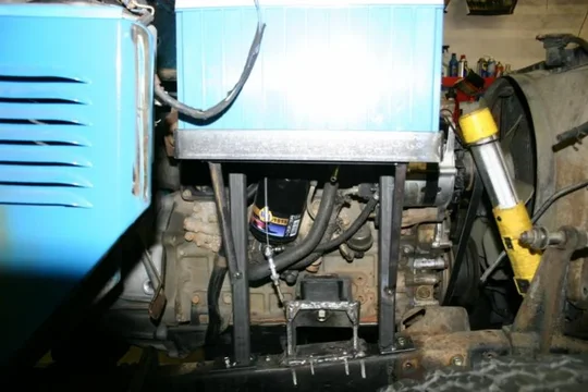
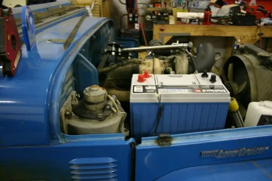
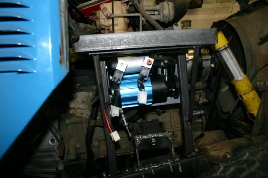
I've also got a DieHard Platinum Group 31 Marine battery for it. It is a very tight fit on the right side of the engine bay, but I think it'll work. The tightest bit is around the vacuum tube from the alternator, so I will likely bend that a bit to help it clear when the motor is torqueing over a bit. I REALLY like that battery--it is a good alternative to a dual battery setup, it's got that much reserve capacity. I'll also have to build a heat shield between the battery and the exhaust, but that should be pretty easy.

Dan
steering 1.webp
steering 2.webp
steering 3.webp
 
Last edited:
take a look at the HZJ40 build and you will see the parts i used to connect it all. the parts are all factory and do nto need cutting or welding.

nice build, cheers.
 
take a look at the HZJ40 build and you will see the parts i used to connect it all. the parts are all factory and do nto need cutting or welding.

nice build, cheers.

You used a 60 series TRE at the pitman arm, a late 40 series TRE on the right side of the relay rod, and a 70 series relay rod, correct? I *thought* that was what I had ordered, but apparently not. I got a 70 series tie rod instead, and a replacement TRE for the right side of the 40 TRE. I just haven't gotten around to ordering from someone who actually gets what I want (I'm thinking there were some crossed lines with 4 Wheel Auto when I ordered it up).

Anyway, I got to fabbing up a battery tray....

The battery is a group 31 Diehard Platinum. This single battery is a pretty good alternative for a dual battery setup. This thing has HOURS of capacity at more amps than all the accessories on the truck can draw together, so I like the simplicity of the single battery, but the MASSIVE capacity of this one.

First off, it all fits, and I've even got plenty of room to fit my hand between the battery and the hood when it's on.
battery 1.webp

Here's a pic showing how it's constructed. I used existing bolt holes in the frame (the original battery tray bolt hole in the front) to attach it to the frame, 1"x1"x1/8" square tubing, and a little bit of 1/2" angle to support it.
battery 2.webp
I will also attach a small bracket (or rubber perhaps) between the battery tray and the fender/apron bolts to support it a bit more at the top too.

And underneath the battery there is BARELY room for the ARB air compressor.
battery 3.webp

There is not much room at all to work with. But I think I got it with enough clearance from the engine so that when it torques over it should still clear the battery. I will also add a heat shield on the back corner to protect it all from the heat of the turbo and exhaust. Additionally, I will add a small plate on the front of the assembly to mount the power relay for the compressor.

Next step (this afternoon) is to get to fabricating my auxiliary starter/glow plug switch panel, which will also double as a place to mount the Racor fuel filter.

Dan
battery 1.webp
battery 2.webp
battery 3.webp
 
So, I stopped by American Toyota today to see what CDan could order for the last of the steering linkage....

Turns out he had everything I needed on the shelf! Good stuff.

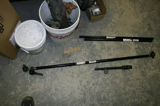
So, here's what I bought:
  1. FJ-60 LH Relay Rod End (goes into the pitman arm)
  2. FJ-40 LH Tie Rod End (comes with new tube, and I already have a new 555 RH TRE)
  3. FJ-40 RH Relay Rod End (that goes into the RH TRE)
tie rods 1.webp

And the part numbers...
tie rods 2.webp

And here they are mocked up together.
tie rods 3.webp

I'm going to order a custom Relay Rod tomorrow threaded on the left side for the FJ-60 Relay Rod End, and threaded for the FJ-40 Relay Rod end on the Right side. That will be the only non-Toyota part in the steering system, so I am pretty happy with that.
tie rods 1.webp
tie rods 2.webp
tie rods 3.webp
 
Here's the clearance between the Relay Rod, the frame and the spring. I think it'll clear without a problem, but I might have to extend the bumpstop a little (hope not).
relay rod 1.webp
relay rod 2.webp

Ever wonder what a new fender for an FJ-40 looks like?
new fender.webp
relay rod 1.webp
relay rod 2.webp
new fender.webp
 
I finished up the battery hold down also. I took the original battery hold down and cut out the "T" pieces, then welded on some tabs and used some simple clamps to let the "T" pieces rotate. I think it came out pretty slick! You can also see the fan motor that Dad prettied up. I'd say it looks great, don't you?
battery tray 1.webp
battery tray 2.webp

And here's the front of the battery tray--you can see there's just not much room between this and the fender. I will make a small bracket from the holes for the ignition coil to help keep it from flexing from side to side.
battery tray 3.webp

Dan
battery tray 1.webp
battery tray 2.webp
battery tray 3.webp
 
rear axle location:
remember tha the axle flexes back and never forward, the more up the travel the further back the axle moves. it is not a straight up travel.
the rear shackle:
yah, remove one of the leaves per side and see if it settles down. i wiould hazzard a guess that you bought the HD kit. if you end up adding a lot of weight then add the leaf back in...

nice, cheers
 

Users who are viewing this thread

Back
Top Bottom
-->