Builds Here we go (FJ-40 getting a 3B/Turbo/H55f)...

This site may earn a commission from merchant affiliate
links, including eBay, Amazon, Skimlinks, and others.

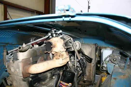
But, since I like the position the motor is in overall, we decided to leave it setting on it's pimped out 2x4s and put the fenders and aprons back on, along with setting the hood on top just to check out how it all fit.

Oh look: the Donaldson fits!
under hood 1.webp

And the turbo has a good two inches before it hits the hood (or it's heat messes with the paint).
under hood 2.webp

And here's a quick overview of the room under there. I like it very much.
under hood 3.webp
under hood 1.webp
under hood 2.webp
under hood 3.webp
 
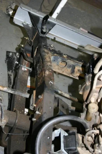
So, because I was happy with how the engine is sitting, Dad and I cut the shock tower off of the left frame rail.
left frame 1.webp
left frame 2.webp
left frame 3.webp

This is just getting ready for a 60 series PS conversion.... The Ftowers (Ford F-250 shock towers) should be in tomorrow, so I'll be able to get something done attaching them.

But really, I need to get back to the tub while I wait to find a better right side engine mounting bracket. Because the next real step after that is to set the tub back on the frame to make sure that the shift levers and everything still fit the way I think they will. ;) Worse comes to worse I'm sure I can fab up an engine mounting bracket out of 1/4" steel. But I like the big, heavy cast brackets better.

Dan
left frame 1.webp
left frame 2.webp
left frame 3.webp
 
Last edited:
Looking good Dan but I agree with you looking for a RHS mount. I don't think a mount ontop of the frame as opposed to inside will be a good idea. Here is my RHD one to give you an idea ..


P1050414.JPG
 
You weren't kidding about the rust! :)

:lol::lol: When I brought it home the wife asked if it came from the Titanic :eek:


I said " yeah, its sunken treasure!"

Should make for good contrast between before and after pics :D
 
So, while I wait on what to do about the motor mounts....

I started the 60 series power steering conversion.

First is a picture of everything that is wrong with the US auto industry. Here is a brand new F-250 shock tower (I bought two, and they are both like this). That metal isn't even stamped straight!!!! WTF?!?!?
shock towers.webp

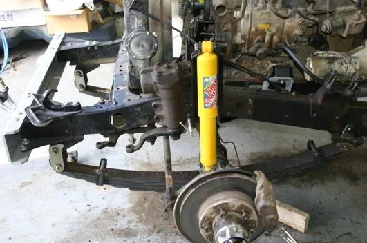
But that little rant aside, I worked as hard as I could to mount the shock tower as far back as possible (to make the drag link/tie rod as parallel as possible to the relay rod). I just tacked it into position here to check fitment.
shock towers 2.webp

And here's a wider picture. This shows how far back I can get the 60 series steering gearbox. It's better than others I've seen posted up, but it's still not entirely parallel.
shock towers 3.webp
shock towers.webp
shock towers 2.webp
shock towers 3.webp
 
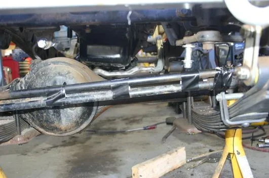
So I wanted to mock up the tie rod to see how it worked. Of course, I don't have anything the right length, so I got creative with some duct tape.
tie rod 2.webp

Here's some pictures showing the tie rod angle compared to the relay rod.
tie rod 1.webp

In this picture you can see the steering turned full leftt. It doesn't bind or anything, and the knuckles move from stop to stop.
tie rod 3.webp

I'm really not sure if that's acceptable or not. Any input? Like I said, the knuckles move from stop to stop, and the steering gearbox has about a quarter turn left in it when it gets to either the left or the right stop. But the angle seems a little excessive to me--am I just being too picky?

Dan
tie rod 1.webp
tie rod 2.webp
tie rod 3.webp
 
okay, you will need the 7* cross link, the 1979 and newer ball joints and you are ready to play. no cutting and no welding required.

Lowenbrau enlightened me to this setup. good man, that one...
 
okay, you will need the 7* cross link, the 1979 and newer ball joints and you are ready to play. no cutting and no welding required.

Lowenbrau enlightened me to this setup. good man, that one...

I've read that. I like that. Toyota parts make me happy. Looks like I'll need to get the credit card out for an order.... The 7* cross link has a tab for the steering stabilizer, correct? And I just need one from any LHD 7* truck, yes? Like 45450-69085?

How does that angle look to you? It looks good compared to other 60 series conversions I've seen on MUD, but before I go crazy making everything permanent (it's just tacked in right now) I want to make sure I'm not missing anything.

But back to the engine....

Can anyone measure the cant of the engine? Preferably from the flat spots on the valve cover (that usually have the 3B decal)? That way I can compare the cant of this setup when I eventually figure out the right engine mounting bracket.

Dan
 
OK, got a bit more done today (and yesterday, etc...)

First and foremost: there is no rust left in the tub to preclude welding the quarter panels back on!!!!

I do need to reattach a corner brace on the right rear, but Dad was busy working on that brace this weekend, and it's ready to go now. So, with that reattached, the quarters should be at least tacked into place tomorrow.

Also, I've been working on the 60 series PS conversion (when this is all done, I'll probably write up a single thread for the 40 series FAQ on it).

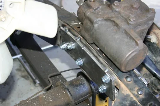
The plates on the frame are just tacked in position, and I just drilled 1/2" holes for the time being.


But here's how it lines up with the steering gearbox and Ftower bolted on.
ps 1.webp

And some detail of how it sits. Compare this to crusher's response in his 1HZ thread and you'll see I've got the PS box a little more than an inch farther back. My tie rod isn't quite parallel, but close enough to it. I like where this one sits.
ps 2.webp

And the back side... I made the inner frame plate long enough to also get the bolts for the F-250 shock tower. Right now it's just 1/2" holes for the bolts, but I will eventually sleeve the bolts with 1/2" Schedule 80 pipe (the I.D. is just over 1/2", and a 12mm bolt is 0.47" in diameter). you'll notice that the aftmost upper PS box bolt hole is a bit high on that sheet. I'll weld on a little ear to give me something better to drill into and attach the sleeve to.
ps 3.webp

I've got lots more updates, but it's time to head to the HDC meeting, and I still don't have to go back to work until Thursday. A lot is getting done.

Dan
ps 1.webp
ps 2.webp
ps 3.webp
 
Yo Bro,

Wanna see who can get thier project done first? I sure hope it is me, cause I'll need my truck soon.

Looks good, lets see some pics fo the finished tub.
 
Yo Bro,

Wanna see who can get thier project done first? I sure hope it is me, cause I'll need my truck soon.

Looks good, lets see some pics fo the finished tub.

Buy a basket case--then we can race building my 45. I'm honestly hoping to have Dad's 40 running for the train trip. We'll see how that goes, eh.

Pics of the tub this afternoon!

Dan
 
Look ma! No clamps!
quarter 1.webp
quarter 2.webp
quarter 3.webp

Just spot welded on the left side. I'll finish the welds tomorrow, and hopefully put the right side on as well.

I looks and feels good to get that done. The right side is ready to go, I just have to put a couple holes in the flange by the rear doorjamb and the right side is ready too.

With any luck, the body mounts will be in tomorrow, so I can set the tub back on the frame to make sure I like where the engine is sitting.

Dan
quarter 1.webp
quarter 2.webp
quarter 3.webp
 
you are a WAY better welder than i am,
congrats, looking good.

Well, those are spot welds (with the HEAVY spot welder). The real test will be welding the seam between the original quarter and the new metal. That's part of today's project.

I love the spot welder though. It really does make perfect little dimpled welds.

I can't wait to get the seam welded, ground down, and then a skim coat of cheap primer just to see it in one color again. That's when it will really look nice I think.

I'm *hoping* to have the tub out for soda blasting the first week of September, so that I can get it primed in good epoxy primer soon thereafter.

Dan
 
OK, so here's to make up what was lost when MUD crashed....

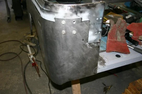
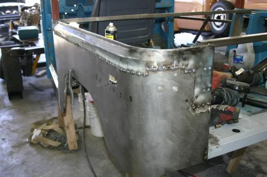
Welding the seams of the quarter panels...

Left side tacked up.
welding 1.webp

And the right...
welding 2.webp

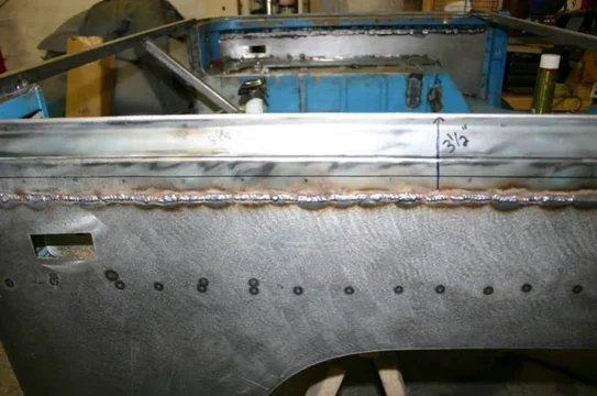
And a closeup of the welds on those seams. I'm happy with them. Flanging the original metal made welding that sheet metal seam very easy.
welding 3.webp
welding 1.webp
welding 2.webp
welding 3.webp
 
But back to some mechanical stuff.....

So, with the 60 series PS swap, we've got to do something about the steering column. Since this is a factory 40 with PS, I didn't want to cut the original column at all (since someone would probably find that most useful with the 40 PS box).

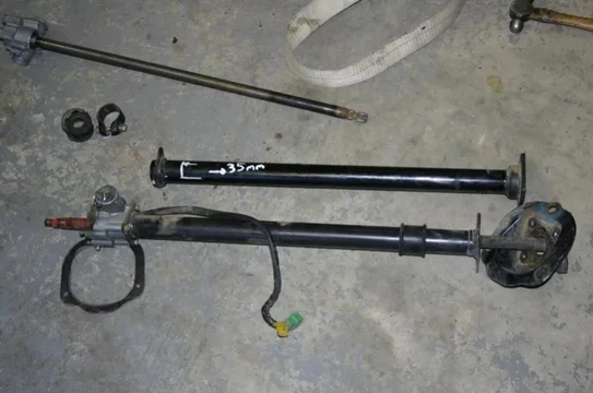
So, we got a column from an FJ-55. Here's the 55 column and the 40 PS column. The 40 column has the rag joint on the end, and still has the "bucket" that goes through the firewall on it. The 55 column is the one with the splined end (those splines just happen to match the splines on a 60 series gearbox).
column 1.webp

Here's the disasembled 55 column. There's really nothing to it. All the "bits" from the 40 will attach to this seamlessly (like the ignition, the plastic housing, etc...)
column 2.webp

But here's where some work is needed. The 40 column is about 35mm shorter than the 55 column. That little bit (a bit more than an inch) really makes you feel like the steering wheel is really in your face.
column 3.webp

I'll come back to this in a bit.
column 1.webp
column 2.webp
column 3.webp
 
To go any further I really needed to see the body on the frame.

So that's what we did. Myself, Dad, two HDC members, Mom and a neighborhood friend were all there so we put the tub on the frame.
body 1.webp

I am either lucky, or a genius! This is where my math said I should put the 3B/H55f to keep the shift levers close to their stock location (and give room for the E-brake without cutting the crossmember on the frame). I'll need to do something about the T-case lever, because that picture is in 4 Low and it hits the inside of the plate in High range, but a little bending should easily take care of that. I couldn't be happier with how this turned out.
body 2.webp

And here's a view from a few feet back. Look at that shackle angle and how far forward the axle is!
body 3.webp

The top case of the H55f BARELY touches the body. It rests on the body mounts, but just barely. So I'll actually move the motor and transmission down about 1/2" to make up for that. Easier than running a small body lift, IMHO.
body 1.webp
body 2.webp
body 3.webp
 
Last edited:
We also decided to put the fenders and hood on real quick just to make it look like a cruiser again. (and to check some things, but really just to look at it)
body 4.webp
body 5.webp

And here's a picture of the left floor area. I plan to add a second battery down here, along with the frame tie in for the roll cage, so it's good to see this room.
body 6.webp
body 4.webp
body 5.webp
body 6.webp
 

Users who are viewing this thread

Back
Top Bottom