fj40 carb cooling fan...do you run yours?

This site may earn a commission from merchant affiliate
links, including eBay, Amazon, Skimlinks, and others.

MoCoNative said:
I've done some thinking on this. I started looking for timed relays, that would function like the stock computer/relay.

Here are some links: The first looks very promising as does the second one. I'm not a good enough electrical designer to tell which one would work from the third link, but there are many possibilites.

http://www.inpowerdirect.com/docs/PDS-60D.pdf
TDRSRXP-12V | Time Delay Relays
Search results for "time delay relay" - Allied Electronics

An adjustable thermostat can be obtained for electric cooling fans easily. For a blower, for those of us that never had one stock, or can't find one, I wondered if a Bilge blower would work. They are weatherproof, cheap and would move enough air I bet, something like this:

Bilge Blowers - Wholesale Marine

Just some thoughts, I'd like the timed relay, then I would know the fan could not possibly run all night if the thermostat screwed up or something.

What I've learned on this tread is if you have the cooling controller/relay the the wiring is most likely there and that the temp sensor is a simple contact switch to ground when the ignition is set to off and it senses some hot temp. It would be great to know what temp is comes on at (those with a temp gun and have them).

I believe a simple temp sensor with a deadband (so it does not cycle back an forth). Like on at 140 and off at 130F would work. I have the same thing on my solar attic fan on my house. Mount it close to the engine to replicate.

However I plan to go back stock and will be on the hunt for one. May have to bite the bullet and give $OR some more of my green.
 
Nope. It's from an fj55. Look at the pic of SurfPig's engine bay. It mounts to the radiator support on an fj55.

The arrow is pointing at the top mounting bolt.

Well look at that...

The fan cooling circuit was fxxxered by the PO so I installed an adjustable electronic fan sensor. Everything else is original. What really heats things up under the hood is that blasted thermonukular exhaust manifold.

:bang:
 
Your top pic shows the engine temp sender (wire running to firewall). Your second pic looks to have the mini wire harness (blue wire) to the carb cooling fan manifold temp sender electrical taped to a pice of tubing. The manifold temp sender ("thermistor' as people are calling it) on a '78 model is located on a small metal bracket bolted to the driver's side of the intake manifold below and slightly aft of the carb with two bolts. Not as reliable when running headers. Without the big heat sink of a cast exhaust manifold the sender often doesn't get hot enough to function. Don't know if they're still available. Specter lists part 182-85B at $167.51. Ouch!

Maybe in your neck of the woods the thermocouple does not get enough heat loading to turn the blower on. Here in Tucson, that blower comes on every time I use the vehicle long enough to get the engine to operating temperature and yes I have ceramic coated headers which help lower the temperature in the engine bay by passing more exhaust heat out the tailpipe. I've been running this setup for about ten years or so and have had no issues with the blower not coming on when it is hot outside.
 
Here in Tucson, that blower comes on every time I use the vehicle long enough to get the engine to operating temperature...

Location is everything. I don't think I've ever had one come on when there was snow on the ground in any of the LC's I've owned. My current one has quit working altogether but I haven't experienced any vapor lock. :meh: I should probably fix it before I get stranded waiting for the engine to cool down. It is summer and all.
 
Just some thoughts, I'd like the timed relay, then I would know the fan could not possibly run all night if the thermostat screwed up or something.

What about a KISS setup? No thermostat - just a timer that runs the fan for 10+ minutes whenever the key is switched off. Maybe add a kill switch to shut it off when working on the vehicle?
 
BTUMAN said:
Thanks. That confirms it. Big help. Ouch is right. Will check one more time but looks like I have to get a new one if I want the cooler. Big help guys. Great thread.

Found the right bracket with no temp sensor. Off to hunt one tomorrow at local cruiser shop. Was being used to hold up fuel lines above headers.

image-2524926301.webp
 
bsevans said:
This is the best photo I have. You can see that the bracket the thermistor is mounted to is bolted to the intake manifold.

This actually is the correct location. Mounted on the intake hard to see though. Thanks bsevans. I found one today from one of our great sponsors and vendors- Cruiser Corps. It was one one of their donor 78s. Pick a part so to speak. Mike and Scott and Dylan are great guys.

I have disassembled and repainted, etc. Will mount tomorrow. The fuse was blown at the fan controller and I wonder if that is why the PO/main restorer left it off.

Should get the carb fan tomorrow from another great cruiser fan and we will see what happens after I clean it up and install.
 
Found the right bracket with no temp sensor. Off to hunt one tomorrow at local cruiser shop. Was being used to hold up fuel lines above headers.

View attachment 550803

Sorry to tell you but that's not the correct bracket for the sender. What you've got there is a PCV valve hose bracket. It bolts to the top of the intake manifold.
 
numby said:
Sorry to tell you but that's not the correct bracket for the sender. What you've got there is a PCV valve hose bracket. It bolts to the top of the intake manifold.

Yes I found that out. One mudder showed it hooked up that way. I responded saying that bsevans was correct. Here it the one I got going back in this morning.

image-3169704439.webp
image-1674150611.webp
 
One more pic.

image-212566183.webp
 
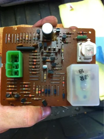
After installing the working cooling fan and thermocouple, and getting engine very warm (105 here today so not much effort) I had no fan working. I pulled the cooling fan relay. Cleaned and inspected -had some corrosion. I scraped it and could not tell if it was just dried coating or what.

Based on picture can I assume the board may be bad? After cleaning it looked ok. Double checked fuse and have power to either side.

Anyone know how to test this thermocouple?

I assume it grounds out or open circuits when it gets to temp (found it was 175F base on one post). Can you similate this on the end of the connector it attaches to fool the computer that there is a ground so the fan would be on when ignition? This would confirm it is an issue with the computer and not the thermocouple (pulled from an old parted out 78).


image-777766906.webp
image-373718203.webp
 
Last edited:
Here is why having a Dec 1978 is very weird. I think I have the 1/1979 wiring for just about everything including the Cooling fan relay.

A lot of late '78 models have wiring that might be similar to 1979 models. Four wires to the alternator, a different fusible link set-up, maybe a few other things. I don't know 79 models but I've seen some wiring harness differences in those later '78s.

Searched mud and SOR and there it was- a second fan relay for 1/79.

Not sure it's applicable or not. Where is the second 1979 relay located? That would solve your mystery as there would have to be a connector for it. If the fan relay is stamped 1978 then I'd think you wouldn't need the second relay. What is the part number on it?

Can someone confirm this is the harness (white)and mount (upper right of pic)for the second relay? PO taped it up out of the way and I didn't notice it earlier. See pic. Note cooling fan relay marked with 1978 date.

Or is this the harness for the seat belt relay and buzzer? I have not figureed out why my light is not coming or or no buzzing.

If there are five wires to the four sockets on the connector it could easily be your seat belt warning relay connector.
 
Yes it was the sea belt. I edited my post about the same time you were replying I guess.

I think you are correct - show 1978 so must be only relay. SOR just show "cooling Relay #2" not sure unless that is the thermocouple I want to test my thermocouple for sure since it was pulled off of another donor and was to test if relay bad. Since it is a single wire to thermocouple I thought it might be a on off type deal and not based on gradient temp and associated resistance. Anyone know?
 
Anyone know how to test this thermocouple?

IIRC when the sender gets hot enough AND you turn off the engine then the fan will come on. I think it is just an on/off swicth in reality. That's why there are two power sources to the box (one is blk/ylw and the other is grn/wht) and one triggers the box to use the other once you turn the engine off. Then the timer takes over to determine run time. There is also a small fuse near the relay under the dash as well as the stop light fuse in the fuse block.

I assume it grounds out or open circuits when it gets to temp (found it was 175F base on one post). Can you similate this on the end of the connector it attaches to fool the computer that there is a ground so the fan would be on when ignition? This would confirm it is an issue with the computer and not the thermocouple (pulled from an old parted out 78).

I "think" if you grounded the thermocouple wire and had power to the blk/ylw input and then cut that power the fan should come on and run on the power from the grn/wht input (small fuse) - at least for a while and even if you then ungrounded the thermocouple. HTH I need to do this too so you're my guinea pig.:)
 
Last edited:
Ok nimby. Let's get this figured out. I will try some more tomorrow if I get time. I didn't check the fuse on the block. Crap, getting out of bed now to go check that- would not be able to sleep if I blew that fuse messing around........ok it was not blown. I know the other fuse was originally blown but replaced and have power on both sides.
 
Last edited:
You need to make sure you have ground continuity from the thermocouple to the intake manifold. Make sure that the paint on the mounting bracket does not interfere with the ground path. I've run into this issue on numerous brackets, but the loss of ground on those was due to powder coating.
 
Yes I thought about that and scrapped the paint off where it mounts to bracket. But just thought that I didn't do that for the mount to the header- and I have three coats on there. Could be part or all of it. Thanks for the heads up. Got in a hurry.
 
You need to make sure you have ground continuity from the thermocouple to the intake manifold.

In my case the sender has gone kaplooey. Hit it with everything from boiling water to a cig lighter to a propane torch. Nada. So I grounded the wire to a good known (and tested) ground location and cycled the ignition. Still nothing. Fan works beautifully when given 12v. All harness wires tested good for continuity and power is getting to where it should with the exception of to the fan from the controller (light blue w/ red tracer on 78 models). Figured that meant the box was bad. Used the ohm meter to test every resistor, diode, relay, switch, etc I could reach - virtually everything - and got measurable readings throughout. I'm not an electrical engineer so I couldn't attribute correct function to anything but there were informative moments such as having some of the bits continuing to build resistance over time or only reading in one direction. Some variation between identical components as well. Tested the entire PCB for continuity. All good. I gave up after a few minutes of testing the component connection to the tracing on reverse side for cold solder joints. Just too tough to be accurate while flipping everything from one side to the other. If I can find my soldering iron I may try to reflow.

No wonder this system has quit working.:rolleyes:
 
Last edited:
Here is the latest on my quest to get this working. I hate to admit, but I'm an Mechanical Engineer by trade and hated my electronics classes. Had to pull from my memory on this one.

The thermocouple creates varying resistance with changes in temp. I hooked up my multimeter and put it on OHMS and before startup it showed 25kOHM. As the engine warms up it slowly goes down in resistance to near zero.

I believe the cooling fan relay assembly looks at this resistance and magnifies (you can see the amp on the board) signal to open and close an electronic relay that switches power for carb fan direct to battery when up to temp and ignition off. It does not seem to be a timer t all but is reding the resistance. See pics showing changing resistance as it warms up. As it cools the resistance went back up. Well engineered if relay worked- but perhaps to well engineered.

Based on this test, I believe my cooling fan relay is bad or there is a wiring issue to the controller. I didn't determine the wire at the relay from the thermocouple or I could have made sure the same resistance is getting there. Will know more later as working relay on order. Thermocouples are inherently robust so chances of a bad one is slim.

image-2420955375.webp
image-882787432.webp
 
Installed the new to me used cooling fan (thanks Summit Cruisers) relay and everything works now. It comes on now like it should. Also thanks to offcamber for the good used parts.

The problem is that perhaps I never got it warm enough. It worked after a 20 mile trip and I wonder if my old one would do the same. I had only let it idle for 30 min before.
 
Last edited:

Users who are viewing this thread

Back
Top Bottom