
Navigation
Install the app
How to install the app on iOS
Follow along with the video below to see how to install our site as a web app on your home screen.
Note: This feature may not be available in some browsers.
More options
Style variation
You are using an out of date browser. It may not display this or other websites correctly.
You should upgrade or use an alternative browser.
You should upgrade or use an alternative browser.
fj40 carb cooling fan...do you run yours?
- Thread starter michaelharrisco
- Start date
This site may earn a commission from merchant affiliate
links, including eBay, Amazon, Skimlinks, and others.
numby said:Have you tried grounding the wire to the thermocouple to see if the fan will come on every time?
Yes. That will not work. The relay is smarter than that. It has more electronics on it than just about anything I've seen on this rig. Apparently expects to see a slow reduction in resistance and a slow increase in resistance- all from the thermocouple.
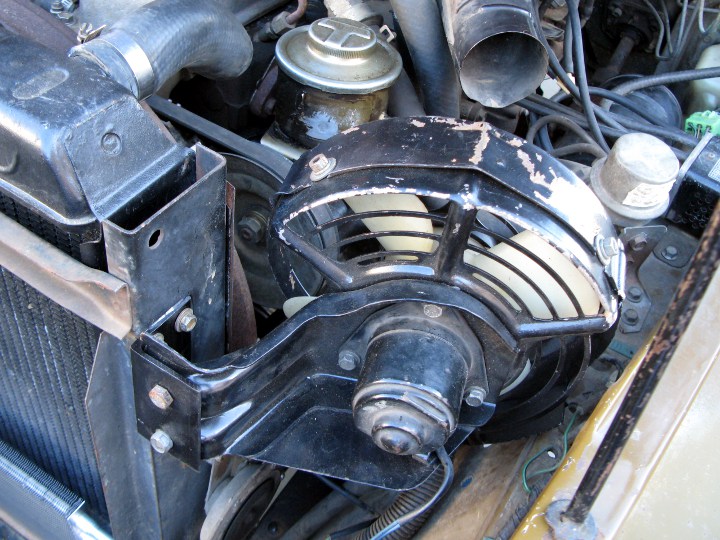
Its warming up outside so I thought I'd warm this thread up. I spent a couple of months this winter converting to an Aisin carburetor so now it's time to dig an old cooling fan out of a box and see it I can get it operational for starts on hot days ahead. So far I've only done the easy part, tearing it down and getting it cleaned up, tested and remounted. Here are a few pics.

This weekend I will see if I can use the info in this thread and get it to work.


This weekend I will see if I can use the info in this thread and get it to work.
Last edited:
My fan came from an fj55. I bought it at the Stockton swap last year, but it's an fj55 fan. I didn't know. I built a bracket to mount it on the radiator upright. I replaced the under-dash fuse, but the carb sensor isn't yet hooked up.
Here's a picture of the carb sensor from a '78. It mounts to the intake, on the bottom, aft of the carb, facing inwards, way back under there.
Here's a picture of the carb sensor from a '78. It mounts to the intake, on the bottom, aft of the carb, facing inwards, way back under there.
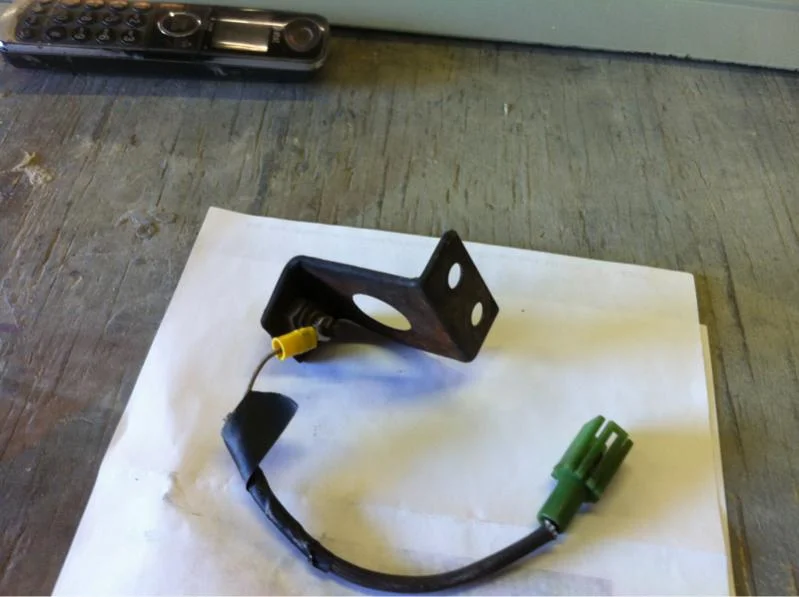
Here is where my sensor has always been located, this weekend I will pull it and test it with the Ohm meter and oven. The wires are a little frazled so I need to clean that up.
If it tests ok then I'm going to take your advice and mount in on the intake where the tab extends below the intake thus getting it closer to the headers. I think the loop at the end of mine may have originally wrapped around the air rail before a desmog (based on couple pics in this thread). Thanks for the input, I'll let you know how this turns out

If it tests ok then I'm going to take your advice and mount in on the intake where the tab extends below the intake thus getting it closer to the headers. I think the loop at the end of mine may have originally wrapped around the air rail before a desmog (based on couple pics in this thread). Thanks for the input, I'll let you know how this turns out
This thread is a bit convoluted, but aren't "they"?
Anyway, I am going to the garage today and this is on my project list. Actually #1 on the list. I am pretty sure I remember seeing the in-line fuse by passenger footwell. Now I assume this is connected to the box/timer unit which is where my question lies. Is this box singular in its performance or does it share other functions. I am not afraid to go new places but recognizing bad solder etc, especially in a multifunction box might be outside my comfort zone.
This is from memory..... There is a large box - seat belt indicator etc? and then a small box...the small box, I believe, it is over/covers the in cab filter for dizzy??? Any pics of the proper box/controller that pertains to the cooling fan?
Again, thanks for the shortcut to this link and "mustard" I do think it appropriate timing to re-hash the thread.
I know Poser is big on FAQ (said respectfully) I think this is definitely appropriate for FAQ. Although I did not look, heck might be there.
Thanks again heading to garage... Wish me luck.
77mustard40 said:Here is where my sensor has always been located, this weekend I will pull it and test it with the Ohm meter and oven. The wires are a little frazled so I need to clean that up.
If it tests ok then I'm going to take your advice and mount in on the intake where the tab extends below the intake thus getting it closer to the headers. I think the loop at the end of mine may have originally wrapped around the air rail before a desmog (based on couple pics in this thread). Thanks for the input, I'll let you know how this turns out
I know you have been told that that is the temp sending/indicator sensor. But your pic is not the only pic I have seen two sensors up there.
Off subject question--> are there occasions/applications where individuals require/want two temp sending sensors up there?? If so what are they?
(should those be a new thread?) if so I will cut and paste and start a new one...
Here is where my sensor has always been located, this weekend I will pull it and test it with the Ohm meter and oven. The wires are a little frazled so I need to clean that up.
If it tests ok then I'm going to take your advice and mount in on the intake where the tab extends below the intake thus getting it closer to the headers. I think the loop at the end of mine may have originally wrapped around the air rail before a desmog (based on couple pics in this thread).
I don't think that is the carb fan sensor. I've got a '76 and a '78 and they're about the same, and different than that.
Fast Eddy said:I don't think that is the carb fan sensor. I've got a '76 and a '78 and they're about the same, and different than that.
I'm really not sure but when I pull it off it's current location and turn it around where you can see it straight on it looks identical to the pic in post 70 and a lot like post 38. I will pull out my electrical diagrams and chase some wired to report back.
Sent from my iPhone using IH8MUD
I will pull out my electrical diagrams and chase some wired to report back.
Awesome. I'm guessing that it will run down into the emissions computer. Those wires may not be listed in the regular FSM schematic. They may only be in the emissions manual. You could probably trace them by color and strip to the diagnostic connector if that is the case.
Last edited:
now it's time to dig an old cooling fan out of a box and see it I can get it operational for starts on hot days ahead.
Are you running headers? Do you even need a cooling fan if you don't have an exhaust manifold bolted to the intake manifold?
Pighead said:Are you running headers? Do you even need a cooling fan if you don't have an exhaust manifold bolted to the intake manifold?
Yep MAF 6-1 headers and have the fuel return line in place but I'm gonna run the fan anyway. This will be my first summer with the stock carb and as hot as it got in Texas last year I'm not taking any chances.
Sent from my iPhone using IH8MUD
Ok in from garage...
Checked the carb cooling fan direct to the battery - it works
I have continuity to everything into the box and out of the box. Something inside issue box is not working??
Do you see anything I am missing?
(I have no idea what to look for here)


Checked the carb cooling fan direct to the battery - it works
I have continuity to everything into the box and out of the box. Something inside issue box is not working??
Do you see anything I am missing?
(I have no idea what to look for here)
I've always wondered if any one has ever installed a cheapy 12V. fan from an auto parts store and wired it through a toggle switch so you could run it by hand? Maybe one of those isn't powerful enough? I would think any air movement would be better than none.
I don't see any obviously bad solder joints on that. You could try connecting the cable to it and checking the connectivity on the back side of the board.
You could wire the actual carb fan to a switch, or to a thermostatic fan controller from Summit and a SPDT relay so it only came on when you turned off the engine. I'm guessing the Toyota version has some circuitry to make sure it doesn't cycle off and back on a few times. The simple version likely would.
You could replace the whole thing with a regulator, a couple transistors, a PIC and a few lines of code. I should do it in my spare time...
Have time to consider the dilemma at hand I have a specific question this time.
Which wire (if known) tells the motor to "NOT" turn on. I just realized there has to be something that tells it not to? I understand the circuit completes itself when the key is off..... But there has to be a wire involved in that switching process....?? (thinking out loud)
I have worked diligently to not take any shortcuts.... Many hours and a few extra bucks to get this thing 78 operational. Would prefer to try and remedy this before going to a MOD.
Thanks to all who have input, specifically Fast Eddy who continues to tolerate me. (Insert smiley here) - I don't know how on my phone.
78GroundUp said:Have time to consider the dilemma at hand I have a specific question this time.
Which wire (if known) tells the motor to "NOT" turn on. I just realized there has to be something that tells it not to? I understand the circuit completes itself when the key is off..... But there has to be a wire involved in that switching process....?? (thinking out loud)
I have worked diligently to not take any shortcuts.... Many hours and a few extra bucks to get this thing 78 operational. Would prefer to try and remedy this before going to a MOD.
Thanks to all who have input, specifically Fast Eddy who continues to tolerate me. (Insert smiley here) - I don't know how on my phone.
Just a suggestion, and I'm a step behind you so take it with caution, try testing the temp sender. I remember seeing a post where the resistance cold is close to 25-30 Ohms but when heated the resistance drops to almost zero. I'm thinking (a CPA talking here) that the sensor in a state of low resistance allows the current to complete its path and "turn on" the fan. Also saw a post where a Mudder bypassed the sensor with an alligator clip on the ground to the sensor and attached that clip to the brake line along the firewall to close the circuit, in this configuration the fan ran each time the key was moved to the off position. He simply removed the clip in colder weather to " turn it off". Best of luck as I hope to be working the same problem tomorrow afternoon. Good beer, BBQ and neighbors ran interference this evening. Cheers!
Top of the day gents. Not a fix but more like a quick experiment, I moved what I think to be the sensor away from the obviously bad location to a better one. The wiring is in bad shape so I will do it right this weekend. Just wanted to see if anything happens.
Sent from my iPhone using IH8MUD


Sent from my iPhone using IH8MUD
hey 78groundup looking at your picts I have noticed a few things. First take a fine bristle wire brush to the trace side of the board to clean it up and remove all the posible shorts. Then when you are done working on it and have it fixed just sray some clear coat on it for corosion protection. Hard to be sure from the pics it is not supporting glue but in pict 3 it looks like your electroltic cap has puked itself. If it has it will be at best weak if not open and will need replaced.Lastly in pict 4 - top right solder joint like it might a ring indicating a crack. Hope I have helpedOk in from garage...
Checked the carb cooling fan direct to the battery - it works
I have continuity to everything into the box and out of the box. Something inside issue box is not working??
Do you see anything I am missing?
(I have no idea what to look for here)