building more LPB beds... come watch

This site may earn a commission from merchant affiliate
links, including eBay, Amazon, Skimlinks, and others.

Hey MASTER ...! Have you think about the 1983 Toyota pick up parts i've talk to you . Let me know if we can do something on that.

Thnx.............................Hum Fingre licking good....:popcorn:


Marc-Antoiner Ethier
 
Updates coming - tomorrow night :D


IMG_0523.webp


I'm such a tease :o
IMG_0523.webp
 
No time for a video tonight so I'll post some pics - I have some small video clips I'll edit and post in the next few days.

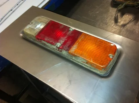
So, as hinted at by the photo above, I wanted to improve upon my last version of the rear valence. Previously my rear valence was simply a flat channel without the recessed or embossed bit around the tail lights.

This is a sample of the late model tail light cut out.
IMG_0520.webp
I made a tool to press in the recess by laminating layers of sheet metal. This picture shows a 0.200" recess. I ended up actually making it .400" in the end - closer to factory. Naturally the metal stretches and makes my hole pattern not fit the tail light anymore so I changed the layout and punched the cutouts small to allow the stretched pattern to fit the tail light
IMG_0522.webp

IMG_0521.webp
IMG_0520.webp
IMG_0522.webp
IMG_0521.webp
 
A rear shot - late model
IMG_0524.webp
And thanks to 3_puppies lending me a mid sixties tail light (and tailgate hinge) I was able to do the same for the early light.
IMG_0525.webp

IMG_0528.webp
IMG_0524.webp
IMG_0525.webp
IMG_0528.webp
 
And so after altering the layout for the punch I was able to make all the rear valences.
IMG_0529.webp
IMG_0529.webp
 
The above goings on occurred last weekend.

yesterday I was able to perform the tail light emboss task and then finish them off with an offset for the rear posts and the two long bends. Wasn't easy to bend them with the emboss there without squashing the emboss.
IMG_0553.webp

IMG_0554.webp
pressed in the nuts too
IMG_0556.webp


Also formed the top rails for the bedside but forgot to take a picture
IMG_0553.webp
IMG_0554.webp
IMG_0556.webp
 
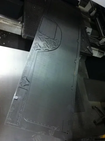
Today I managed to shear blanks and punch out all of the floors, bed sides, hooks, front wall stiffeners and access covers.
IMG_0565.webp

IMG_0564.webp

IMG_0560.webp
IMG_0560.webp
IMG_0564.webp
IMG_0565.webp
 
It seems I had less good video than I thought so I patched together some clips

 
Outstanding work, Kevin.

Hmmmm. Could the embossed tailgate letters be on the horizon?
 
Oh yeah!

Well I'm going to give it a try anyway. I have learned in my limited experience of embossing that the thicker the metal the less distortion of the surounding flat area. The tailgate skin I make is 16 Ga and the tail light valence is 12 Ga - a full 0.040" thicker.

We'll see....
 
Progress last Sunday consisted of finishing all of the punching for the beds. I now have to bend them all.

I will post a little video as soon as I get a chance.
 
In an effort to obtain more rum......


Last edited:
Depends on the part of course. The controller is capable of full 3D drawing of the part but I usually draw 2D cross sections. You sketch the profile and assign a dimension that you need. Then pick and load the tools you are using from the library and position them on the graphic so it knows where they are. Then tell it the sequence of bends while it shows you a graphic of pre and post each bend so you can see collisions with the tooling or machine.

Basically you tell it the tool, material thickness and how long a flange you want and step on the pedal. It will calculate where the backgauge needs to be to hit the flange length you want using a given tool. First bend is usually +/-0.010" and then you can fine tune from there.

The rear corner post I did in a video above was about an hour to program and I burned the first two parts fine tuning the angles and flanges. You have to visualize the whole process to know what sequence to bend a multi-bend part so that the first bend doesn't preclude the second, third or fourth bend from being possible. Good mental orthographic projection skills are required.
 
Awl_TEQ said:
Depends on the part of course. The controller is capable of full 3D drawing of the part but I usually draw 2D cross sections. You sketch the profile and assign a dimension that you need. Then pick and load the tools you are using from the library and position them on the graphic so it knows where they are. Then tell it the sequence of bends while it shows you a graphic of pre and post each bend so you can see collisions with the tooling or machine.

Basically you tell it the tool, material thickness and how long a flange you want and step on the pedal. It will calculate where the backgauge needs to be to hit the flange length you want using a given tool. First bend is usually +/-0.010" and then you can fine tune from there.

The rear corner post I did in a video above was about an hour to program and I burned the first two parts fine tuning the angles and flanges. You have to visualize the whole process to know what sequence to bend a multi-bend part so that the first bend doesn't preclude the second, third or fourth bend from being possible. Good mental orthographic projection skills are required.

So how many extra parts do you typically punch in order to burn some?
 
:) Depends on the part. If it is complex with multiple bends using more than one set of tools I might make two or three. If it is just an angle or channel I might not make any.

Another factor is size. If I need 10 but 14 parts fit nicely across a 48" sheet I will make 14 and use the spares as set-up pieces in the brake or during subsequent processes. If I get to the end and have one or two extras I will either recycle them or store them if it is a recurring part.
 
Been watching this thread and got to say that is some top notch work there going on.
 
You're gonna have to shorten some of these videos, and edit one nice beginning to end clip. Fantastic work!!! :cheers:
 

Users who are viewing this thread

Back
Top Bottom