Builds Benjamin’s 3D Prints Build (6 Viewers)

This site may earn a commission from merchant affiliate
links, including eBay, Amazon, Skimlinks, and others.

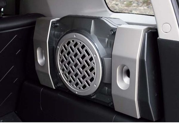
Something similar to what you see here. Found this on OverlandBound’s Instagram a while back.

View attachment 2197417
I have a NIB dual 4ohm voice coil bazooka tube I bought for another project that I've thought about mounting similar. I'm not sure the factory amp would push it though, even if I wire it from a dual 4ohm to a single 2ohm final independence.

Amazon product ASIN B0007WQ7KI
 
Last edited:
FWIW The subs in the FJ cruiser work pretty well if you can find a take off somewhere. The sub & box are a removable unit.
Fj cruiser subwoofer
 
I was able to install my Make 7v1 from Ben today! Looks pretty sharp. Thanks Ben! I also installed the Make 1 (scangauge) but didn't take any pictures. :)

View attachment 2216970


Ran the power all the way through the cab to my 6-fuse power distribution block.

View attachment 2216971
Is that hot all the time? If so, the LED for the USB will drain your battery. I had to add a switch to one I installed some years ago.
 
Make 6 V6:

6V6.1 Overview of the Final Product

View attachment 2171411

View attachment 2166734

Note: Ram ball mount CAD credit to Neal@grabcad.com (Free CAD Designs, Files & 3D Models | The GrabCAD Community Library).

6V6.2 Introduction

The original pocket cover only snaps into the main panel. If you fix a Ram ball mount directly on the original cover, with some load like an iPad, it tends to pop out. With this two-piece design, we should have a more secure fixture.

6V6.3 Design and Fabrication

The fasteners used will be provided. For reference, they are listed here.
Steel Narrow-Base Weld Nut
Alloy Steel Low-Profile Socket Head Screw, Black-Oxide, 10-24 Thread Size, 1" Long
Note: The measurement was taken on my 2000 LC. The pocket contour may be a little off from a LX. A little bit of sanding or trimming of the part may be needed.

6V6.4 Purchase List to Complete the Installation

RAM Diamond Ball Base

6V6.5 Purchase Link

PM for Direct Paypal Payment

Price:
$29 + $7.9 (USPS Priority) for printed in ABS.

I would like to order one of this. I have a 2001 Land Cruiser. Do you carry the ram ball mount as well or should i source it on my own? Any website to go to to make the purchase?
 
I would like to order one of this. I have a 2001 Land Cruiser. Do you carry the ram ball mount as well or should i source it on my own? Any website to go to to make the purchase?
Easiest way is to send him a PM and do the order that way. When I ordered my USB change pocket blank he ordered the appropriate USB connector for me and then just added to charge, so he would probably do the same. Not going to be something he "stocks" though as he is building these as orders come in I believe.
 
LED panel mount printed in Tan. Will try to print on smooth plate to have a better surface finish.

Any source for high quality LED panels? The ones on the picture get really hot.
The only way to reduce the heat is to reduce the power of the LED array. This can be done by decreasing the input voltage or changing the current-limiting resistors on the PCB. Both of these approaches will reduce overall brightness.

The PCBs will get hot by design. Those PCBs are fiberglass so the copper layers on the top & bottom will dissipate heat if exposed to air. The way you have it mounted, though, eliminates airflow from the top (LED) side of the PCB where most of the heat will want to be radiated. Plus it looks like about a third of the bottom layer is covered by your mounting piece. But since there's only a few vias between the top & bottom layers heat transfer between the two is limited anyways. So the bottom layer isn't able dissipate that much heat even if it was fully exposed.

Bottom line: If you want the array to run cooler and last longer the top (LED) side needs to have some means of airflow for natural convection cooling. Maybe some vent holes and raised standoffs between the housing and PCB. Hope this helps. :)
Thanks!
There is no air flow behind panel. I am adding a PWM controller to dim the LED.
 
So a few weeks ago I was at my little cousins baseball game and my uncle likes to record the entire thing from behind home plate so that my cousin can see and correct his swing, grip, stance, etc... Well my uncle uses a GoPro Hero 8 at 4K60fps, and if you have one of these cameras and record a lot of footage at that resolution you know that they get extremely hot, especially when you're in the sun. They actually get so hot that they can turn off and corrupt your footage. So what he did was install a couple small aluminum heat sinks to the top and sides of the GoPro and now he can record all 4+hrs of gameplay at 4K60fps without any issues. Maybe that could be something you could incorporate on the back of the PCB?? Then again you would also need somewhere for that heat to go besides being trapped in the headliner and baking like an oven, but it's an idea.

1583886636775.png
 
So a few weeks ago I was at my little cousins baseball game and my uncle likes to record the entire thing from behind home plate so that my cousin can see and correct his swing, grip, stance, etc... Well my uncle uses a GoPro Hero 8 at 4K60fps, and if you have one of these cameras and record a lot of footage at that resolution you know that they get extremely hot, especially when you're in the sun. They actually get so hot that they can turn off and corrupt your footage. So what he did was install a couple small aluminum heat sinks to the top and sides of the GoPro and now he can record all 4+hrs of gameplay at 4K60fps without any issues. Maybe that could be something you could incorporate on the back of the PCB?? Then again you would also need somewhere for that heat to go besides being trapped in the headliner and baking like an oven, but it's an idea.

View attachment 2235394
Thanks. I will have one heatsink in the back and add one PWM controller to dim the LED. It is too bright now.
 
About to do a 7.1 install (rear console USB outlet.) Got two wires coming from the 12 volt - one black and one black/white stripped. Any way to tell which is positive?
 
About to do a 7.1 install (rear console USB outlet.) Got two wires coming from the 12 volt - one black and one black/white stripped. Any way to tell which is positive?
White-with-a-black-stripe wires are usually ground on our trucks. To be sure you can take one of your turn signal or brake light bulbs and connect one side of it to your chassis and the other side to the black wire. If the bulb lights up, the black wire is +12V.
 

Users who are viewing this thread

Back
Top Bottom