
you sure have put alot of time and good honest hard work into your rig, and it shows...i been on Mud for years and this is the only build i have read each and every comment on. Now im exhausted, myself, like yours, will never be "completely" done, as we like to noodle around, tweak here and there, its a passion, and your passion shows...Great build Man !!!
Navigation
Install the app
How to install the app on iOS
Follow along with the video below to see how to install our site as a web app on your home screen.
Note: This feature may not be available in some browsers.
More options
Style variation
You are using an out of date browser. It may not display this or other websites correctly.
You should upgrade or use an alternative browser.
You should upgrade or use an alternative browser.
Build '74 FJ40 Build: My 1st Cruiser
- Thread starter gpfj40
- Start date
Member Builds and Stories
This site may earn a commission from merchant affiliate
links, including eBay, Amazon, Skimlinks, and others.
- Thread starter
- #82
you sure have put alot of time and good honest hard work into your rig, and it shows...i been on Mud for years and this is the only build i have read each and every comment on. Now im exhausted, myself, like yours, will never be "completely" done, as we like to noodle around, tweak here and there, its a passion, and your passion shows...Great build Man !!!
Thanks for the kind words. I have been following the final stages of your build as well over the past year. I’d sure be interested in some more details on your LS install; mount pics, measurements, angle, center/offset, etc. That info could come in real handy over the next week or two.
As I was waiting for the engine swap parts, my ADD caused me to start on the sliders which may evolve into fender protecting tubing with the help of a bud and his pro bender 4. What you see in this pic is just the start using 2” seamless .120 wall mech tubing, then I got side tracked again.

I had an opportunity to sell my 1.5F and 4 speed locally so I pulled it over the past weekend and it is gone. I’m officially committed to making the LS swap work now.


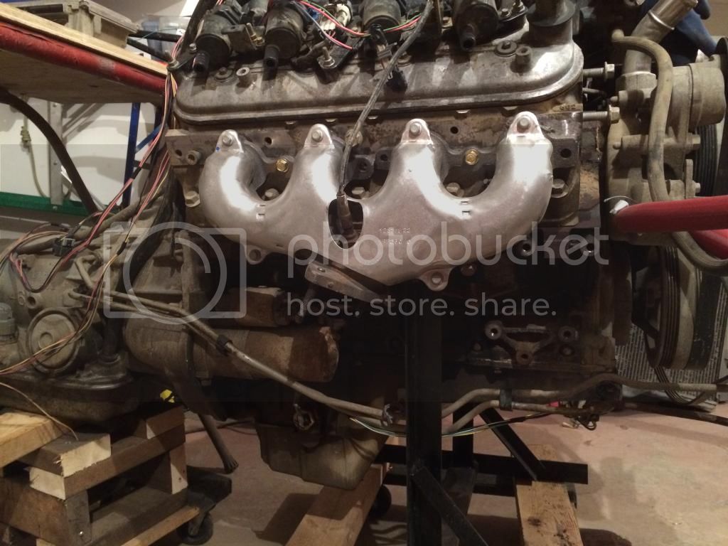
As for the swap: The fuse/rely block is coming along. I sourced a set of exhaust manifolds via Kijiji for $100 off a brand new LS3 CT525 crate engine that was going into a river boat. They will simplify exhaust routing, I hope, as compared to the truck manifolds and they were far cheaper than block hugger headers or hooker LS swap manifolds. Had to purchase new plug wires cause I wrecked a couple pulling the engine. The AA 50-0407A adapter is ordered from NW fab. The ECU is back from LT1swaps and the fuel pump arrived from Tanks Inc. The cooling and PS hoses are mocked up. The fuel system mocked up is yet to be done and there are a few more wires to connect, after that hopefully it will run.

- Thread starter
- #83
The the tube work for the DS slider is close to complete, I forgot to take a pic before I pulled it off. Next up will be to make a mirror image for the PS then weld in some 10 ga sheet metal or similar into the hoop to act as a step or mud/gravel guard.

The AA adaptor arrived and was promptly installed. I ran the engine up to temp on the stand to see if my hillbilly machining install of the Toyota LC temp sender into the PS side head was going to hold coolant and the LC oil sender installed into the LS oil cooler port just above the filter would hold oil. The coolant sensor held perfect and the the oil pressure sender seeped oil past the threads so I applied more tape and sealant to the threads and will hope for the best. I’m not a big fan of loud exhaust but it sure sounded good hearing my LS rumble (through ear muffs). I’m not getting any codes on my code scanner so that is a good sign.
The rest of the brackets etc needed to be removed from the chassis in preparation for the install. Now I need to test fit the drive train and scope out the front drive shaft. An exhaust builders kit is on the way from summit so I’m going to try my hand at welding up an exhaust system once I get the LS mounted.
- Thread starter
- #84
I mocked up the LS and 4L60e this weekend, here was the first try with the T case sitting at centre and the engine 1” to the DS at the pulleys:


I wasn’t happy with the angles or the interference. After some ‘mud consultations, more internet searching and talking to a couple people I decide to lower the engine and the tranny to about the height AA recommends, and place the drive line at a 3 degree angle pointed down towards the rear pinion. I also move the drive train as far forward as I thought possible, with out needing new narrower acc drive mounts. I forgot to take a pic of the T case from above through the tunnel as this would have made it much clearer how far forward and down it was shifted. The engine/tranny/T case are sitting square, 3/4” offset to the drivers side.
This netted me a 24”, 18* rear d shaft with a 0* pinion flange and 3* t-case flange. I’m not sure I could be doing this LS/4L60e swap if my wheelbase was not stretched 9 or 10” into a ’43, the auto would have to go I think. Time will tell if this rear d shaft angle will work. If not i can always turn the pinion straight up at the t case a put a DC CV at the top.
Here are the mounts:


And the ‘strong tacked’ in driveline:


While everything was out I copied a T case reinforcement I saw on the net somewhere and mod’d/braced the AA T-case shifter mount for the 6 bolt hex tranny tail.

There are some un solved issues around my home brew 60 series PS conversion steering shaft to manifold clearance, at this point there is 1/4” between the steering u joint and the manifold. I will likely rework the shaft.

The front drive shaft might clear, it seems a little clearancing will be necessary at the back corner of the tranny pan and the bell housing may interfere with the DS at full stuff. The HP 80 series front axle is certainly complicating the angles and the interference. I’m certain with a regular pinion 3rd this would have good angles with plenty of clearance. Time will tell, I’ll update this after my first attempt to put a shaft in.
For the rad I’m going to use the new champion 2 core aluminum rad I bought this winter. I plan on abandoning the mech fan in favour of a 3300 cfm flex-a-lite 180 15” fan and shroud combo. It’s a little pricey but I’m not finding much cheaper >3000 cfm, not many taurus’ or wreckers around here. It appears I will be reworking the stock rad mount to shift the rad more to centre and forward about 1”. I’d love to figure out how to flatten the threaded clutch mount on the front of the water pump pulley to gain 5/8".
http://www.summitracing.com/int/parts/flx-180/overview/
I wasn’t happy with the angles or the interference. After some ‘mud consultations, more internet searching and talking to a couple people I decide to lower the engine and the tranny to about the height AA recommends, and place the drive line at a 3 degree angle pointed down towards the rear pinion. I also move the drive train as far forward as I thought possible, with out needing new narrower acc drive mounts. I forgot to take a pic of the T case from above through the tunnel as this would have made it much clearer how far forward and down it was shifted. The engine/tranny/T case are sitting square, 3/4” offset to the drivers side.
This netted me a 24”, 18* rear d shaft with a 0* pinion flange and 3* t-case flange. I’m not sure I could be doing this LS/4L60e swap if my wheelbase was not stretched 9 or 10” into a ’43, the auto would have to go I think. Time will tell if this rear d shaft angle will work. If not i can always turn the pinion straight up at the t case a put a DC CV at the top.
Here are the mounts:
And the ‘strong tacked’ in driveline:
While everything was out I copied a T case reinforcement I saw on the net somewhere and mod’d/braced the AA T-case shifter mount for the 6 bolt hex tranny tail.
There are some un solved issues around my home brew 60 series PS conversion steering shaft to manifold clearance, at this point there is 1/4” between the steering u joint and the manifold. I will likely rework the shaft.
The front drive shaft might clear, it seems a little clearancing will be necessary at the back corner of the tranny pan and the bell housing may interfere with the DS at full stuff. The HP 80 series front axle is certainly complicating the angles and the interference. I’m certain with a regular pinion 3rd this would have good angles with plenty of clearance. Time will tell, I’ll update this after my first attempt to put a shaft in.
For the rad I’m going to use the new champion 2 core aluminum rad I bought this winter. I plan on abandoning the mech fan in favour of a 3300 cfm flex-a-lite 180 15” fan and shroud combo. It’s a little pricey but I’m not finding much cheaper >3000 cfm, not many taurus’ or wreckers around here. It appears I will be reworking the stock rad mount to shift the rad more to centre and forward about 1”. I’d love to figure out how to flatten the threaded clutch mount on the front of the water pump pulley to gain 5/8".
http://www.summitracing.com/int/parts/flx-180/overview/
Looking good, finding the optimal spot for the motor and transmission is pretty time consuming, but you're moving right along.
Keep a couple things in mind about an electric fan.
1) they take a lot of current to run, and, if not shut off with the ignition switch they (or it) will kill your battery in very short order. Not as much of a deal on a manual transmission, but a huge deal with an automatic.
2) you can get fairly narrow engine-driven fans. What I used on mine is actually shorter than a comparable electric fan.
2a) be sure your electric fan is narrower, I found on mine that I couldn't fit any kind of large fan on the front of the radiator (which is most efficient - pushing rather than pulling) behind the grill.
- Thread starter
- #86
I took another look at my mech fan clearances, if I mod the rad bracket a little I can get about an inch of clearance. Will that be enough? I'm thinking it is. Part of the reason for going electric was being able to shut it off in deep water but for now I think the easy route will be the way forward.

1 1/2" from the fan blade - and the closer the better... that looks perfect.
I was thinkin' the same thing, looks good to me.1 1/2" from the fan blade - and the closer the better... that looks perfect.
2) you can get fairly narrow engine-driven fans. What I used on mine is actually shorter than a comparable electric fan.1 1/2" from the fan blade - and the closer the better... that looks perfect.
Super, What model and year has the narrow engine driven fan clutch and fan? is it narrower than a silverado application fan clutch with blade?
what would the minimum clearance you advise? <1.5"
Thanks Garrett
- Thread starter
- #90
I installed the Tanks Inc Walbro pump and bulk head in to my custom fuel tank. It fit beside the tank level float once I bent the float wire a bit. I opted to skip the backing ring with all of the threaded bolt holes in favour of tapping and threading M6 bolts directly into the 12 ga tank.


I have a plan to rework my steering shaft so I’m going ahead with the C6 manifolds rather than the DS truck manifold in the most recent pic. I cut some flanges out of 3/8” steel with the plasma and used a 2.5” summit brand exhaust builders kit to build the crossover to y pipe system.
http://www.summitracing.com/int/parts/sum-670146
At full bump the 3rd member just touches the cross over pipe. I’ll need to reroute 1 wire loom now that I have chosen to come forward to cross over, I honestly couldn’t see any other way of running the PS exhaust. I have to say I’m surprised how well this part of the project went, I was loathing having to cut and fit all of those angles but it was far simpler than I expected. Having a kit with tubes with consistent diameter throughout the bends certainly helped. The kit has enough exhuast pipe to make 2 full systems.


I also built a double battery tray out of so 1” and 3/4” angle. It is bolted to the frame like the stock tray, rather than the fender. Battery hold down straps are yet to come, I’ll likely use some 4” wide strips of 16 ga to do this.

I have a plan to rework my steering shaft so I’m going ahead with the C6 manifolds rather than the DS truck manifold in the most recent pic. I cut some flanges out of 3/8” steel with the plasma and used a 2.5” summit brand exhaust builders kit to build the crossover to y pipe system.
http://www.summitracing.com/int/parts/sum-670146
At full bump the 3rd member just touches the cross over pipe. I’ll need to reroute 1 wire loom now that I have chosen to come forward to cross over, I honestly couldn’t see any other way of running the PS exhaust. I have to say I’m surprised how well this part of the project went, I was loathing having to cut and fit all of those angles but it was far simpler than I expected. Having a kit with tubes with consistent diameter throughout the bends certainly helped. The kit has enough exhuast pipe to make 2 full systems.
I also built a double battery tray out of so 1” and 3/4” angle. It is bolted to the frame like the stock tray, rather than the fender. Battery hold down straps are yet to come, I’ll likely use some 4” wide strips of 16 ga to do this.
I put dual batteries on my H3, one of the best mods I did.
where are you mounting your fuel tank?
where are you mounting your fuel tank?
2) you can get fairly narrow engine-driven fans. What I used on mine is actually shorter than a comparable electric fan.
Super, What model and year has the narrow engine driven fan clutch and fan? is it narrower than a silverado application fan clutch with blade?
what would the minimum clearance you advise? <1.5"
Thanks Garrett
I'm running a gen 1 vortec sbc, so it may not interchange with the LS motor - that said, I used a fan and clutch assembly from a 97 Tahoe - then picked the "thinner" one... it was an eduguess on Rockauto that paid off... no less than 1 1/2" from the blade to the radiator. the fan pulls towards the radiator at speed, 1 1/2 is the closest GM puts their fans - so I figure their validation is enough for me.
- Thread starter
- #93
I put dual batteries on my H3, one of the best mods I did.
where are you mounting your fuel tank?
Check out post #18

very cool... 12 ga is pretty strong, so this note is if you want forever rather than solid.... weld some flat bar from seam to seam next to the mounting points to keep cracks at bay. welding creates more brittle metal through the heating process - thus running bars on either side of the welds distributes that load over the entire distance... with that said, it will probably be fine forever if you just leave it alone as well.
I need to re-look at that spot on my rig - where the tank is is a pain, and putting it in the back would be so much better... of course, I don't have the extra space - so it couldn't completely mimic...
I need to re-look at that spot on my rig - where the tank is is a pain, and putting it in the back would be so much better... of course, I don't have the extra space - so it couldn't completely mimic...
Last edited:
- Thread starter
- #95
very cool... 12 ga is pretty strong, so this note is if you want forever rather than solid.... weld some flat bar from seam to seam next to the mounting points to keep cracks at bay. welding creates more brittle metal through the heating process - thus running bars on either side of the welds distributes that load over the entire distance... with that said, it will probably be fine forever if you just leave it alone as well.
I need to re-look at that spot on my rig - where the tank is is a pain, and putting it in the back would be so much better... of course, I don't have the extra space - so it couldn't completely mimic...
I thought long and hard about where to put the tank. It was imperative to get it out of the passenger compartment. I considered building one to go in the space ahead of the axle on the DS much like the later 40s. Your links will mess that spot up I think. My frame is 14” longer so you will end up less than 18 gal if you build a tank in the spot I chose to. As for the strength advice, thanks but at this point I’m going to see how it holds up.
Now for the update:
Here is the ECU mount, I made it out of 18 ga and cut down the plastic chev ECU holder to hold it to the mount. It is attached to the fender in the washer fluid tank location, not the firewall, which makes it a little flexy. It will do for now, time will tell if it will hold up. I bought a weather pack connector kit and put it to use where my ecu/truck harness connects to the truck so I don’t have to unhook every plug on the engine to pull it.


Here is the new crossmember, the old one needed to be removed because of the longer drivetrain. It is 2” DOM and is inserted through both walls of the frame just like the stock one. It is just mocked there at the moment, I’ll be welding some scab plates on the inside to fill that factory oval hole in the inside frame.

I built the intake using a 4” alum elbow tube, silicone coupler, silicone elbow and K&N cone filter from summit and the stock chevy MAF. This is the only place I think there is room so it has caused a couple of changes. I will need to switch to a electric fan; it appears that a flex-a-lite #180 will fit the space. The other problem with the intake placement is it interferes with the inlet of the LC replacement alum champion rad. The the solution was to take the rad to a local shop with TIG alum welding skills and move it to the PS. Since it was at the welding shop I had them add a 1/4” npt bung for the LS steam port.


- Thread starter
- #96
I pulled the drive train out to final weld the mounts, fix up the floor, weld in the cross member and do a few other things that are easier while it is out. After doing all this I reinstalled the drivetrain. This pic was taken during the reinstall:

This is a flex a lite 180 3300 cfm electric fan. I chose to go this way because the stock mech fan left no room to plumb the intake to the DS, combined with my slightly higher mounted engine with a taller truck manifold, while using dual batteries on the PS. The rad mounting bracket is original FJ, although I moved the rad down about 1 inch in the bracket and moved it forward 1 inch by drilling new holes in the bracket mounts. This shift forward was possible because I reworked my grill to take up less space back at post 65. Both of these adjustments were necessary to leave room for the fan and allow the hood to close now that the rad is further forward. I was back and forth about using the ECU to control the fan but it is not programmed in at the moment so the flex a lite controller will have to do.


The exhaust is done back to the muffler, I painted the welds with VHS flame proof paint. Probably a waste of time but it takes attention away from my poor exhaust pipe welding. I used band clamps in 2 spots so I should be able to remove it down the road without cutting. I spent a little time wrapping select wiring with heat shield tape. You can also see the crossmember and scab plates in this pic.


Here is the final resting place of the drivetrain, it is mounted at about 4 degrees down at the back:


To shift the 4L60e I chose a black B & M Magnum Pro Stick. I will modify the cable linkage mount a little to move it away from the exhaust. The plan is to build a enter console to mount the shifter, 80 series e brake handle, CB and possibly an auxiliary heater.

The steering shaft mod is complete too, it was simply redoing it and having the upper u joint right after the steady bearing on the firewall. This gave enough clearance to us the C6 manifolds with their heat shields. I forgot to take a pic before I reinstalled the intake, but if you look close in the second pic below you can see the shaft and u joint.
THE PAYOFF: 6 or 7 weeks ago I pulled the 1.5F, today I was able to drive my LS powered 43 around the block for the first time seated on a tool box. I’m sure it is not a record speed swap but I’m pretty happy none the less. The drive was cut short because of my failed attempt to use a 3 piece lower rad hose which leaked everywhere and I have not wired the fan up yet. I’m going to order one of those flashy rad hoses from summit.


This is how it looked after it’s maiden LS powered trip, sans front bumper/winch:

This is a flex a lite 180 3300 cfm electric fan. I chose to go this way because the stock mech fan left no room to plumb the intake to the DS, combined with my slightly higher mounted engine with a taller truck manifold, while using dual batteries on the PS. The rad mounting bracket is original FJ, although I moved the rad down about 1 inch in the bracket and moved it forward 1 inch by drilling new holes in the bracket mounts. This shift forward was possible because I reworked my grill to take up less space back at post 65. Both of these adjustments were necessary to leave room for the fan and allow the hood to close now that the rad is further forward. I was back and forth about using the ECU to control the fan but it is not programmed in at the moment so the flex a lite controller will have to do.
The exhaust is done back to the muffler, I painted the welds with VHS flame proof paint. Probably a waste of time but it takes attention away from my poor exhaust pipe welding. I used band clamps in 2 spots so I should be able to remove it down the road without cutting. I spent a little time wrapping select wiring with heat shield tape. You can also see the crossmember and scab plates in this pic.
Here is the final resting place of the drivetrain, it is mounted at about 4 degrees down at the back:
To shift the 4L60e I chose a black B & M Magnum Pro Stick. I will modify the cable linkage mount a little to move it away from the exhaust. The plan is to build a enter console to mount the shifter, 80 series e brake handle, CB and possibly an auxiliary heater.
The steering shaft mod is complete too, it was simply redoing it and having the upper u joint right after the steady bearing on the firewall. This gave enough clearance to us the C6 manifolds with their heat shields. I forgot to take a pic before I reinstalled the intake, but if you look close in the second pic below you can see the shaft and u joint.
THE PAYOFF: 6 or 7 weeks ago I pulled the 1.5F, today I was able to drive my LS powered 43 around the block for the first time seated on a tool box. I’m sure it is not a record speed swap but I’m pretty happy none the less. The drive was cut short because of my failed attempt to use a 3 piece lower rad hose which leaked everywhere and I have not wired the fan up yet. I’m going to order one of those flashy rad hoses from summit.
This is how it looked after it’s maiden LS powered trip, sans front bumper/winch:
nice job!
- Joined
- Jul 7, 2014
- Threads
- 8
- Messages
- 52
This build is truly awesome!! Now all you need is some new wheels! haha