3F-E Conversion Thread (1 Viewer)

This site may earn a commission from merchant affiliate
links, including eBay, Amazon, Skimlinks, and others.

Thanks again for sending me the modified schematics, Russ. I think I was able to successfully connect everything following your notes with the exception of the (BY) charge light relay wire from the alternator.

Can you explain why you connected it to the (BY) ignition wire?

On a related note, since the FJ40 has no charge light on the dash, can I just delete the (YW) charge lamp wire (from the alternator) and fuse from the panel?


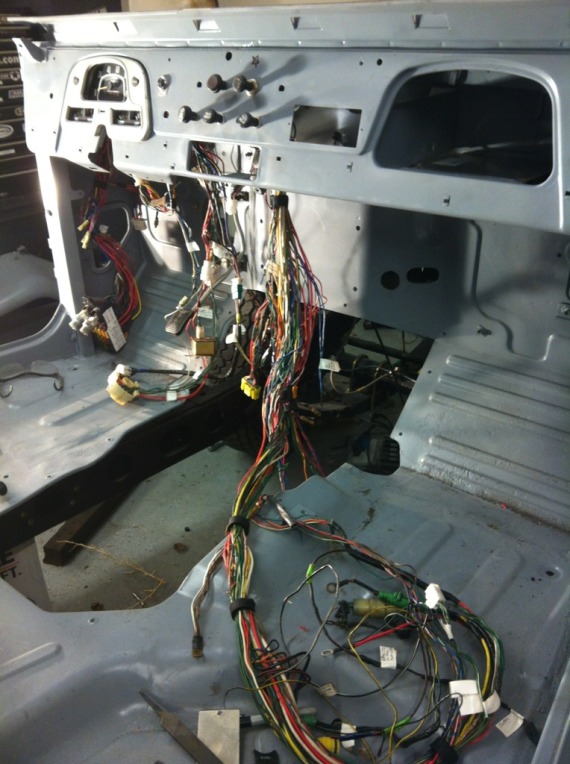
Here's where I am at right now:

"HOUSTON, WE HAVE A MESS"

C5960B01-3DA0-4D67-BFBD-7603C90C9BB6-19239-000022725F9F2A00_zps3f417611.jpg


This is probably the scariest part so far. I decided to reuse the FJ62 fuse panel and modify the FJ40 mounting brackets to accept it. This is so daunting at first it's easy to think, "I'll never get this running". But, even when I get completely stumped and aggravated, usually all it takes is a 15 minute beer break and when I come back with a clear head, I have (so far) been able to figure everything out.

I'm also going to use the two circuit breaker mounting points to hold the "ignition main relay" and the newly added "switched power ECU ignition relay" <--- see 73tlcv8's notes above. to the fuse panel for neatness.

8BA4DE67-3ED4-4C51-BCEF-85C30B0CEA89-19239-000022727C5373A2_zpsb0748bc6.jpg


The ignition main relay is unaltered from the FJ62 schematic, the switched power ECU ignition relay has been added to take some of the load off the stock 4 wire ignition switch.

Now, I'm down to trying to figure out how to mate the FJ40 tail lights, marker lights and brake lights as well as the front headlights. The FJ62 used relays for all these components while the FJ40 did not. I don't think it's worth the effort to add relays for the rear lights but I definitely want to add a pair of relays for the hi/low beam circuits up front. I've got a Painless relay harness kit incoming so I'll be playing with that very soon.

The only other thing I've been working on is the Autometer gauge kit from Amateur.

C3032414-813C-4D52-8447-22B9B8AAB1DF-19239-0000227282D29229_zps80768f27.jpg


I've got everything mounted except the gauge cluster faceplate since I'm having it repainted. I've also painted the speedo needle and fuel gauge needle white to match the autometer needles.

Yaya!

b45c50e2-1d02-4f48-9114-deb7c8ccf5fc_zps0b713bf1.jpg
 
Gimme till mon i have a alt wiring schematic that will help

Sent from my phone using IH8MUD
 
Gimme till mon i have a alt wiring schematic that will help

Sent from my phone using IH8MUD

I think I may have answered my own question. After looking at the charge light relay on the diagram, it looks like it gets it's power from the (BY) wire coming out of the engine fuse. So, I just tapped the (BY) wire from the alternator into the (BY) wire between the engine fuse and the new switched power ECU relay.

Hopefully I got that right.


I would really like to test this harness before I go through all the trouble of reinstalling it. I figure there's a likelihood something - somewhere - got missed or messed up. I've even thought about laying it all out, hooking up the switches, relays, lights and a battery and trying it out while laying on the floor before putting it back in the truck. I'd obviously have to simulate a chassis ground to several components, but I think it is doable.
 
I did not use the charge relay or light, just hooked the BY wire from the engine fuse to the IG terminal of the alternator. Your use of the 62 fuse panel was a good idea, your work looks good.

I laid my harness out and powered it up and checked (almost) everything before wrapping it up and installing. I forgot the RB wire to the start injector, I didn't figure out until later. Make sure to use the non stick harness wrapping tape, you don't want the nasty mess from electrical tape.
 
I'm still plugging away at this. Now, I've got the wiring harness pretty much done (I hope) and have laid it out to test it. I hooked up all the lights, switches and relays to it and used jumper wires to simulate the chassis ground. I also installed a Painless relay kit for the hi/lo beams. It just seemed to be a good time to do it since everything was torn apart.

So far, I've got working brake lights, tail lights, 4 way flashers, back-up, hi/lo headlights, horns, wipers and side markers working. Now I'm getting more involved with testing the EFI tidbits.

The open circuit relay is working; as are my two new ignition relays. Now I'm sitting down with the FJ62 FSM and am going through the troubleshooting checklist for the ECU. I'm taking baby steps here. If I can just get power to the starter, I'll be happy (for now).

Speaking of starter... before I can actually get the engine bolted in, I need to get the correct motor mounts powdercoated and bolted in. I'll be visiting the powdercoating shop this week to drop off the bellhousing, mounts, pulleys and other goodies to be spruced up.

The next step is to test mount the engine in the frame and install the wiring harness temporarily to check for fit. I don't want to tape it all up only to find that "this wire is too short" or "that wire's too long". Once I'm satisfied that everything works and won't interfere with any other parts, it'll all come back out to be cleaned up, painted and the harness wrapped. Also, I've got a cool idea to neatly mount the ECU in the glove box. I'm going to cut a rectangular hole in the left side of the glovebox the same size as the socket side of the ECU. This way, I can bolt the ECU down snug against the side of the glovebox and the ECU connectors will just attach from the outside of the glovebox. I think I'm going to cut a second grommet hole, next to the original one for the engine mounted harness to pass through the firewall.


More to come.
 
I've been cleaning up the engine so I don't have to mess with a filthy engine. I've got it torn down to a long block and should have the parts back from the powder coater in a couple weeks.

In the mean time, I'm playing with finding homes for several additional components. I found (what I think) is a good place for my Wilwood proportioning valve. I also mounted the relay bank to the cowl. I bought a very expensive riv-nut tool so I've been going absolutely crazy finding things to riv-nut. :)

I was at Georg's swap meet in the lovely city of Stockton last weekend and I ran into a guy there who also had a 3Fe conversion in his 40. I took a lot of pictures and it was invaluable seeing one in person and up close. He is running the stock FJ62 brake booster and an 80 series MC. The interesting thing is that he flipped the booster upside down to get it to fit without modification. I'll have to look into that.


QUESTION!

If I'm going to dump all the smog components, do I still need the charcoal canister?
 
Keep the charcoal canister, it is good for the environment. I ran mine thru the vacuum temp switch on the thermostat housing so it only sucks on the canister when the engine is warmed up.
 
Careful with Powdercoating the motor mounts. Be sure that that the ovens won't impact the bonded rubber. Might be ok, but I would paint those instead. I powdercoated a brand new crank pulley and the process melted the bonded seal and threw it out of true, making it trash. Expensive lesson.
 
Thanks for the heads up but I'm talking about the motor mount brackets, not the actual rubber motor mounts. :) The PO cut the mount brackets from the frame when he swapped for the V8. I'm just putting new frame brackets back in and they needed to be coated to match the frame.

I did have the outer crank pulley PC'ed as well, but left the harmonic balancer out to avoid the issue you described. I'll just hit it with some satin black and call it a day.
 
Been doing a bit more work on the truck. I've been trying to figure out where I'm going to park all the EFI components in the limited amount of space available in the 40.

I put the ECU in the glovebox. I really tried hard to avoid this because I wanted to have the glovebox...well, just be a glovebox. But, there really isn't another location that you can use to keep it high and dry and out of the way of the heater/blower/defroster ducts. If only Toyota had made this thing 2 inches smaller.


I do want to keep it neat as possible so I cut a hole in the side of the glovebox to allow the connectors to attach from the outside of the glovebox. I'm going to make a bracket to hold the ECU in place and use strips of rubber to isolate it from vibration.


The Main Relay is mounted on the back side of the passenger fender:


I decided that the circuit opening relay really didn't look too weatherproof so I put it on the other side of the glovebox:


I'm mounting the distributor vent valve in a location similar to the FJ62. On the passenger side of the firewall:


The brake proportioning valve is low and out of the way on the driver's side:

I'm really digging my new riv-nut tool:


The relay block for the hi/lo beams is mounted on the driver's side firewall too. I have an extra relay position and I'm not sure what to use it for just yet.


I've got the harness sort of attached to get an idea of the fit. I've moved some bits around as needed to fit the FJ40 body better. I added some length to the circuit opening relay so I could move it under the dash. I had to shorten the battery and alternator leads. The 62 is a much bigger truck!


Anyway, more to come.
 
Looks great! I look forward to seeing the final product...thanks for the help btw, hopefully ill have mine running tomorrow...
 
That test fit looks familiar, I lost some skin getting all that put in place in the dash. Looks good. I put some split hose around the edge of the cut out in the glove box to prevent potential chaffing of wires. Cutting that rectangular hole was a pain. How did you mount the fuse panel?
 
Thanks guys.

There is still a lot of small problems to solve, but I'm sure I'll come up with something soon. The factory FJ62 throttle cable will mount up to the FJ40 firewall with just a big of egging of one hole in the plastic tab. I also just had to bend my gas pedal clip a bit to mate to the cable boss but it looks like it's going to work very well.

I'm going to mount the FJ62 fuse panel to the tub in the same location as the original and use the original mounting ears. One will have to be cut and relocated an inch or so to accept the longer fuse block, but it should be pretty easy (except of course welding in an awkward position).
 
Did you modify the 40 pedal of combine the two pedals. I haven't seen many pics or descriptions of how people have done to route the throttle cable and mount the gas pedal.
I am getting ready to do the 2FE conversion (I have a donor FJ62) and I am confident in my abilities to work the engine mechanicals and electrical mods, but the pedal issue is really my biggest unknown at this point.
zgot any pics of the pedal and accel cable routing/mounting?
 
Last edited:

Users who are viewing this thread

Back
Top Bottom