Man I just finished cleaning my roof cap too. Now getting ready to put it back on the truck. Did you use any adhesive on it or just the dry rubber seal ? I did get the one from city racer too. So I might have to stretch the corner like you saidRoofs on, serious fight.
View attachment 2336003View attachment 2336004
Maybe some tech: (1) the city racer LPB roof seal will work on these fixed top SWBs, it needs to be stretched in the corners, otherwise it fits reasonably with door holes aligning and new holes added along the back. (2) I loosely installed bolts along the back first, then propped the front up to get the windshield seal in place, then lowered the front onto both seal flanges, and using the string technique for other glass install I was able to pull the inside flange into position - with a little soapy water - leaving the outside flange in place. Installed other bolts and clamped everything down. (3) But in order to do that, given this is an old rig and I had it disassembled and replaced a lot of metal, the holes didn’t align enough - so I jacked the low side of the frame until everything aligned enough, bolted it up, lowered and nothing popped. I actually did the same thing when I put the cab on to get the proper cab mount height. This thing is sprung to a 1/2 inch of its life. Good weld quality test
.
My daughter’s Brittany Sophie has done her inspection, gave it a claws up.
View attachment 2336011
Navigation
Install the app
How to install the app on iOS
Follow along with the video below to see how to install our site as a web app on your home screen.
Note: This feature may not be available in some browsers.
More options
Style variation
You are using an out of date browser. It may not display this or other websites correctly.
You should upgrade or use an alternative browser.
You should upgrade or use an alternative browser.
Builds 1963 FJ45LP SWB Fixed Top "Sweet Simplicity" (1 Viewer)
- Thread starter middlecalf
- Start date
This site may earn a commission from merchant affiliate
links, including eBay, Amazon, Skimlinks, and others.
More options
Who Replied?middlecalf
SILVER Star
- Thread starter
- #1,082
No sealant or adhesive. But that might have helped keeping it in place as the roof was set, but mostly it was just a lot of finessing the rubber seal into position as I bolted the roof in place. GL, not a fun job especially since there isn't a perfect fit seal for these roofs.
Less weight saves fuel....done.

my helpers help wherever they CAN.
my helpers help wherever they CAN.
Last edited:
double
Last edited:
middlecalf
SILVER Star
- Thread starter
- #1,085
How does “double” save fuel?double
I’ll double your double.
Good thing this is my thread so I can chat with myself
 .
.middlecalf
SILVER Star
middlecalf
SILVER Star
- Thread starter
- #1,087
The 5-minute jobs sometimes are the best!

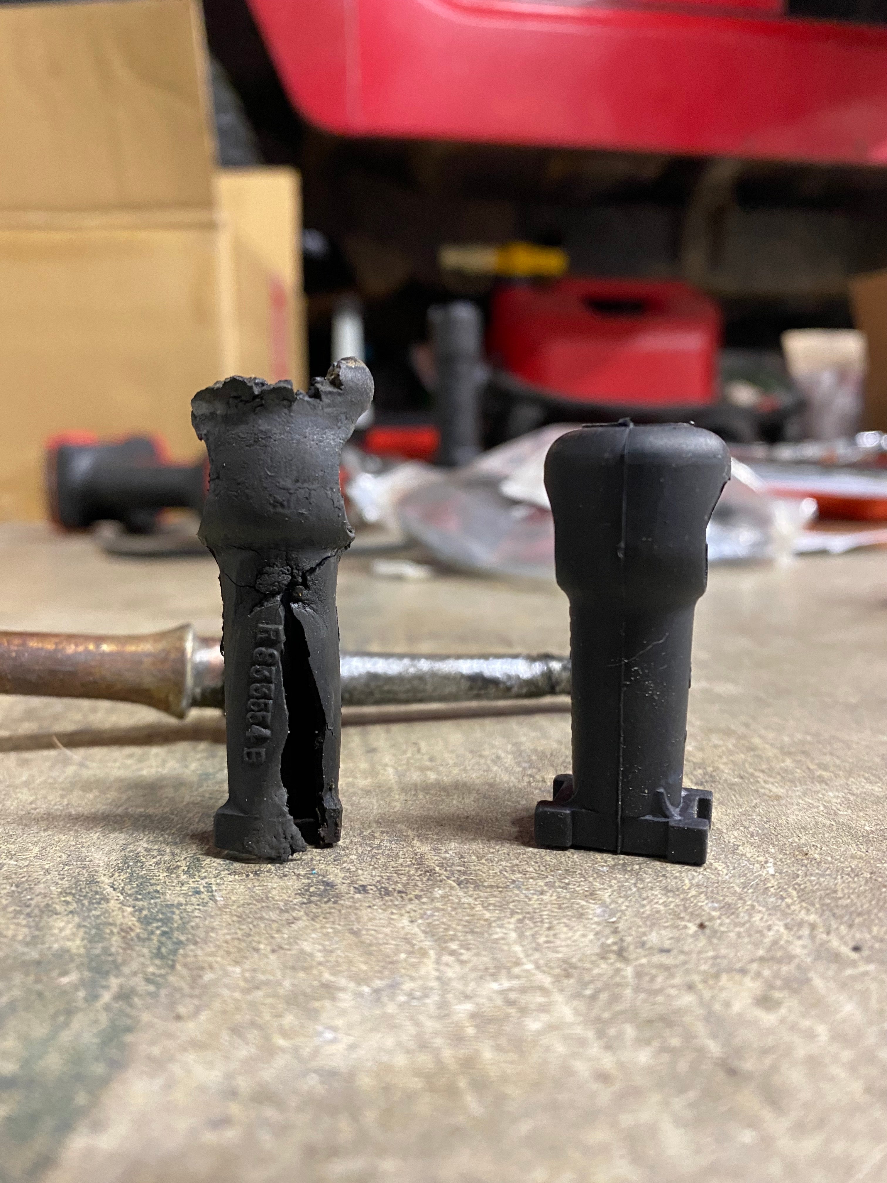
Do you have a 3-speed on the column on your pre-1972 FJ40? Chances are good you need a new bushing for that column shifter! These bushings (often called a "seat") have long been NLA. That didn't stop us here at the Cruiser Cult though. We searched high and low and found a OEM work around! Yes these are genuine Toyota rubber bushings. They are a tad shorter than the originals (see photos) but work just fine where it matters (at the pivot point). The result is immediately clear with a smooth and cushioned lever movement.
There are little "feet" on the bushing that may need to be trimmed before install.
FJ40 3-speed column shifter bushing
Do you have a 3-speed on the column on your pre-1972 FJ40? Chances are good you need a new bushing for that column shifter! These bushings (often called a "seat") have long been NLA. That didn't stop us here at the Cruiser Cult though. We searched high and low and found a OEM work around! Yes...cruiser-cult.myshopify.com
View attachment 2960514
Cruiser Cult
Supporting Vendor
Nice! Easy fixes are the best!


middlecalf
SILVER Star
- Thread starter
- #1,089
So this is fun. Got my new top-secret NSA spy camera from China, 5mp of pure delight. Here’s pics (won’t post boring videos, all the cylinders kept their clothes on):
Cyl 1

Cyl 2

Cyl 3

Cyl 4

Cyl 1
Cyl 2
Cyl 3
Cyl 4
middlecalf
SILVER Star
- Thread starter
- #1,090
Cyl 5

Cyl 6

Spark plugs

Cyl 6
Spark plugs
middlecalf
SILVER Star
- Thread starter
- #1,091
Notes:
1) Markings on cylinders - anyone recognize those? OEM, aftermarket? I have no knowledge of engine‘s history.
2) No holes or obvious damage around periphery of all 6 cylinders or cylinder walls
3) Oil - pretty much in all cylinders, a lot in #’s 2, 3 & 4 - you can see it running down the wall
4) There is a lot of blowby, I have an Elite sump off the PCV system and it’s collecting oil on each trip
5) There is milkshake in the oil fill tube and cap after each trip - none in oil but definitely ”frothed” most likely from blowby as there is no detectable coolant loss, or oil in coolant
6) Plugs are not oily on gap/probe, only on threads
7) good compression all around, no valve flicker or issues indicated from vacuum test
8) high oil consumption, blue smoke starts after engine starts to warm up and oil is coming out of rocker arm
9) valve cover has milkshake only on part over the lifter rod holes
Conclusion - head gasket is compromised in the area around the lifter rod holes and possibly each cylinder, hence the oil seen in each cylinder esp. 2, 3 & 4, burning oil and the excessive blowby.
Plan - pull head, verify validity, check valve guide tolerances, replace valve umbrellas, and replace head gasket.
Hopefullness - cylinder rings are still ok.
Last edited:
EWheeler
GOLD Star
What camera did you buy? The photo quality is great. I don't know much about inside of engines, but those look pretty wet from oil, or is that what they should look like?
middlecalf
SILVER Star
- Thread starter
- #1,093
This one Amazon product ASIN B07MV6X4M4
There shouldn’t be any oil, maybe some combustion by products (moisture, soot). I did bump the engine forward a bit to get room for pics in cylinders 3 & 4 so I guess some fuel/vapor might have leaked it (doubt it, didn’t smell any, all the plugs were pulled).
It‘s a bit of a challenge to get the camera positioned, the cable is stiff, needs to bend through the spark plug hole, and it helps to have each cylinder at the bottom. I couldn’t get a full frame image, but I was able to wiggle the cable and rotate the camera around and see the complete cylinder as well as walls. I bought this camera because it had a better range of focus over some of the others - and I have apple ijunk.
Bear
SILVER Star
Eeeew ! "Endoscope". Don't they use those in other places, too?!
Kidding aside, good job on a thorough check of your engine !
Kidding aside, good job on a thorough check of your engine !
middlecalf
SILVER Star
- Thread starter
- #1,095
Yup, I’ve been through three of the “endoscope” adventures. Not sure what looked better though, cylinders or … well never mind .
Couple more pics of cylinder 1 and 6, actually more of the valve that’s right there. #6’s valve is open so end of exhaust stroke I think so that’s the exhaust valve, and #1’s near valve is closed so end of compression stroke (both cylinders near top). I ordered the 45-deg mirror attachment for this scope so I can better see the valves insitu.
Cyl 6

Cyl 1

.Couple more pics of cylinder 1 and 6, actually more of the valve that’s right there. #6’s valve is open so end of exhaust stroke I think so that’s the exhaust valve, and #1’s near valve is closed so end of compression stroke (both cylinders near top). I ordered the 45-deg mirror attachment for this scope so I can better see the valves insitu.
Cyl 6
Cyl 1
middlecalf
SILVER Star
- Thread starter
- #1,096
My order for the side-mirror attachment for the NSA approved spy camera from China finally arrived, first one got lost enroute in Ukraine somewhere. Kind of hard to use, the camera bore site and mirror bore sight aren’t fully aligned. “That’s normal” per the manufacturer, who suggests getting the dual lens camera if needing high resolution side lookies, for more $’s of course. Anyhow, I could sort of see the valves - ok, not really - but the one I could see the best (Cyl #1) has what might be a crack emanating outward from the edge of the valve bore - maybe. Or it’s a crack in the accumulated gunk. Who knows. Pic is fuzzy, too close of distance for camera’s focal length, in person view is a wee bit clearer.

So what does one do if they find a crack like this? Pull the head? Tear down the motor?
Crap no, put the plugs back in, connect wires, and hit the road. Cruising the local intrastate.

Some more local intrastate cruising. Spring is just starting to show up.

So the CINChouse thinks the 40 is a convenient gardening work bench.

- but the one I could see the best (Cyl #1) has what might be a crack emanating outward from the edge of the valve bore - maybe. Or it’s a crack in the accumulated gunk. Who knows. Pic is fuzzy, too close of distance for camera’s focal length, in person view is a wee bit clearer.So what does one do if they find a crack like this? Pull the head? Tear down the motor?
Crap no, put the plugs back in, connect wires, and hit the road
. Cruising the local intrastate.Some more local intrastate cruising. Spring is just starting to show up.
So the CINChouse thinks the 40 is a convenient gardening work bench.
Last edited:
middlecalf
SILVER Star
- Thread starter
- #1,097
cross post to keep this build thread complete:
on edit: post #1107 in this thread has measurement data
I’ve hunted around a little for the early sender ohm data, this is all I’ve found so far, empirical data (early for me is at least ‘65 or ‘63):

Temp Sender for Early Cluster.
Checked these values for Splangy, thought I'd post it up in a thread since I didn't see it in our old conversations. I believe this applies to all the early 25 and 40 clusters. I did a few readings on a working stock sender so we could have a record of the values, unfortunately it wasn't too...forum.ih8mud.com
I read somewhere else on mud (can’t recall where though
on edit: I strongly suspect an air bubble in my system, esp. since the heater hose that runs from the fitting that the temp sender unit is in over the rear of the engine into the heater core is the highest part of the cooling system so I probably have an air bubble that's keeping hotter coolant from the sensor. Type to burp!
on edit: post #1107 in this thread has measurement data
Last edited:
middlecalf
SILVER Star
- Thread starter
- #1,098
Burping


middlecalf
SILVER Star
- Thread starter
- #1,099
For completeness…. The very same thread above had the answer to questions on these early senders. Getting harder every day to remember what or where I’ve read stuff :
:There is not a lot of information about the early temperature senders/gauges and some of that information is incorrect, which lead me down the wrong path. Maybe someone with a little more clout than I can confirm the information below and update some of the earlier posts in this thread. Hopefully this helps folks avoid the mistakes I made.
Operation of early (pre 9/72) temperature senders:
Much like the early fuel senders, the early temperature senders contain bi-metal voltage regulators and operate as a crude on/off (like really slow PWM) temperature dependent voltage regulator. They are NOT resistive temperature sensors, and trying to measure the resistance as a function of temperature will not work - the resistance is a near constant 35 - 40 ohms, regardless of temperature, as you are actually measuring the resistance of the heater wire wrapped around the bi-metal strip.
These sensors work in a similar fashion to the bi-metal strips wrapped in a heater coil that deflect the needle in the gauges. The gauge applies battery voltage though a ~25 ohm resistor (which is the heater coil on in the gauge itself) to the sender. This causes the bi-metal thermostat strip in the sender to be heated by a coil of resistance wire wrapped around it, and it bends away from a contact, breaking the circuit. As the circuit is now open, the bi-metal strip cools down and returns back to the contact, closing the circuit and starting the cycle again. The duty cycle (how long the circuit is closed relative to how long it is open) sets the average voltage through the sender. Now as the ambient temperature in the sender increases, it takes less time to for the bi-metal strip to heat up as it is already warm, and it takes it longer to cool back down, so the regulator spends more of its time in the open position, which decreases the duty cycle, and thus leads to a lower average voltage. In short, the sender is a temperature sensitive voltage regulator with a decreasing average voltage as the temperature increases.
This also explains why the needle on the early temperature gauges rests on the right (H) side of the gauge when the vehicle is off and deflect to the left. When you start the engine, the sender is cold and is closed most of the time, leading to the a higher average current through the gauge, which deflects the needle all the way to the left (C). As the sender warms up it spends more time open than closed, reducing the average current through the gauge, which then deflects less and moves back the right towards the Hot mark.
Hopefully this helps someone else figure out what is going on with their gauges. Next up my non working fuel gauge/sender combo.
Last edited:
middlecalf
SILVER Star
- Thread starter
- #1,100
First official fence building/repair party 

Not much of a party though, no one else showed up .
.
Not much of a party though, no one else showed up
.Similar threads
Users who are viewing this thread
Total: 2 (members: 0, guests: 2)