
Yes. It's the first thing I did .... but in any case it looks like an electrical problem ... I think the cable goes in and works mechanically inside the gearbox. After 3 years that the car was stationary as soon as the batteries were connected, I immediately noticed the O/D OFF warning light flashing even with the engine off
Navigation
Install the app
How to install the app on iOS
Follow along with the video below to see how to install our site as a web app on your home screen.
Note: This feature may not be available in some browsers.
More options
Style variation
You are using an out of date browser. It may not display this or other websites correctly.
You should upgrade or use an alternative browser.
You should upgrade or use an alternative browser.
throttle position sensor voltage reading 1hd-ft
- Thread starter vicious77
- Start date
This site may earn a commission from merchant affiliate
links, including eBay, Amazon, Skimlinks, and others.
Yes. It's the first thing I did .... but in any case it looks like an electrical problem ... I think the cable goes in and works mechanically inside the gearbox. After 3 years that the car was stationary as soon as the batteries were connected, I immediately noticed the O / D OFF warning light flashing even with the engine offDid you check the kick down cable .?
Hi ... why are you saying this? do you have experience on this? what values should i read in the voltmeter? Thank youI believe the manual is incorrect, for 1HD-T and 1HD-FT, try applying 5v between VA and E2 and measure voltage between VC and E2 @ full throttle.
")
Yes. It's the first thing I did .... but in any case it looks like an electrical problem ... I think the cable goes in and works mechanically inside the gearbox. After 3 years that the car was stationary as soon as the batteries were connected, I immediately noticed the O / D OFF warning light flashing even with the engine off
if there is a flash on the OD light .. there is a code to check.
se c'è un lampo sulla spia OD.. c'è un codice da controllare.
Thank you, you are right and the manual is wrong, I checked by turning the key to ON, I disconnected the TPS "throttle position sensor "connector and I checked the female connector coming from the ECU. In fact I saw that arrive exactly 5V at the sensor in the pin corresponding to the VA pin ..... and in the pin corresponding to E2 I have continuity with the frame (groung) .... IS THIS RIGT???I believe the manual is incorrect, for 1HD-T and 1HD-FT, try applying 5v between VA and E2 and measure voltage between VC and E2 @ full throttle.
After I checked the TPS disconnected from the electrical system; supplying 5 Vdc (VA + and E2 -) and I measured the voltage between VC and E2 and it is always 5Vdc fixed regardless of the angle position of the TPS (I tried to move the throttle rod where the TPS is still mounted but not varied nothing).
Then I checked the resistance between the different PINs of the TPS:
accelerator lever at idle
- E2-VC 2.69 K-ohm
- E2-VA 2.65 K-ohm
- EC-VA 40 Ohm
accelerator lever at maximum (almost nothing changes)
- E2-VC 2.83 K-ohm
- E2-VA 2.66 K-ohm
- EC-VA 33 Ohm
Do you have any ideas? Can the TPS be faulty ???? Do I need to do any other tests? Why did it break only having spontaneously the injection pump ... before did everything work well?
Thank you, you are right and the manual is wrong, I checked by turning the key to ON, I disconnected the TPS "throttle position sensor "connector and I checked the female connector coming from the ECU. In fact I saw that arrive exactly 5V at the sensor in the pin corresponding to the VA pin ..... and in the pin corresponding to E2 I have continuity with the frame (groung) .... IS THIS RIGT???
After I checked the TPS disconnected from the electrical system; supplying 5 Vdc (VA + and E2 -) and I measured the voltage between VC and E2 and it is always 5Vdc fixed regardless of the angle position of the TPS (I tried to move the throttle rod where the TPS is still mounted but not varied nothing).
Then I checked the resistance between the different PINs of the TPS:
accelerator lever at idle
- E2-VC 2.69 K-ohm
- E2-VA 2.65 K-ohm
- EC-VA 40 Ohm
accelerator lever at maximum (almost nothing changes)
- E2-VC 2.83 K-ohm
- E2-VA 2.66 K-ohm
- EC-VA 33 Ohm
Do you have any ideas? Can the TPS be faulty ???? Do I need to do any other tests? Why did it break only having spontaneously the injection pump ... before did everything work well?
Applying 5v between VA (Not VC) and E2 and measuring voltage between VC (Not VA) and E2 @ full throttle with the TPS adjustable range slot approximately in the middle and with screws slightly loosened you should be able to then move the TPS to achieve 0.96v as per the manual.
The other test is the linear 1v to 8v steps through the throttle range at the diagnostic port terminals as per below. However I found this to be a little inconsistent even with a new TPS installed.
There is a lot of information in this manual however I have found some subtle errors send you down the wrong path when looking for a conclusion with confidence.
I am chasing an inconsistent shift change with no electronic or mechanical faults obviously indicated. My transmission is 24 years old though with 420k's on it. I am suspecting a possible lock-up clutch issue (delaminating friction plates from age) but not committed at this point.
I will say the 80 series 1HD FT/Auto are a great vehicle though.

TT TERMINAL VOLTAGE INSPECTION
1. INSPECT THROTTLE POSITION SENSOR SIGNAL
(a) Turn the ignition switch to ON. Do not start the engine.
(b) Connect a voltmeter to check connector terminals TT and
(c) While slowly depressing the accelerator pedal, check that
TT terminal voltage rises in sequence.
If the voltage does not change in proportion to the throttle
opening angle, there is a malfunction in the throttle
position sensor or circuit.
(Note below Tt indication is incorrect, it is one terminal to the left)


The other test is the linear 1v to 8v steps through the throttle range at the diagnostic port terminals as per below. However I found this to be a little inconsistent even with a new TPS installed.
There is a lot of information in this manual however I have found some subtle errors send you down the wrong path when looking for a conclusion with confidence.
I am chasing an inconsistent shift change with no electronic or mechanical faults obviously indicated. My transmission is 24 years old though with 420k's on it. I am suspecting a possible lock-up clutch issue (delaminating friction plates from age) but not committed at this point.
I will say the 80 series 1HD FT/Auto are a great vehicle though.
TT TERMINAL VOLTAGE INSPECTION
1. INSPECT THROTTLE POSITION SENSOR SIGNAL
(a) Turn the ignition switch to ON. Do not start the engine.
(b) Connect a voltmeter to check connector terminals TT and
(c) While slowly depressing the accelerator pedal, check that
TT terminal voltage rises in sequence.
If the voltage does not change in proportion to the throttle
opening angle, there is a malfunction in the throttle
position sensor or circuit.
(Note below Tt indication is incorrect, it is one terminal to the left)
Applicando 5v tra VA (non VC) ed E2 e misurando la tensione tra VC (non VA) e E2 a tutto gas con la fessura della gamma regolabile del TPS approssimativamente al centro e con le viti leggermente allentate dovresti essere in grado di spostare il TPS per ottenere 0.96v come da manuale.
L'altro test è il passaggio lineare da 1v a 8v attraverso l'intervallo della valvola a farfalla ai terminali della porta diagnostica come indicato di seguito. Tuttavia ho trovato questo un po' incoerente anche con un nuovo TPS installato.
Ci sono molte informazioni in questo manuale, tuttavia ho scoperto che alcuni sottili errori ti portano sulla strada sbagliata quando cerchi una conclusione con sicurezza...........
Hai ragione, ci sono davvero degli errori nel manuale, ma le tue informazioni sono state utili per farmi prendere le misure corrette. Grazie!!! Ho riscontrato il problema... Chi ha revisionato la pompa iniezione aveva montato male il TPS (sensore posizione trohtle) che non era tirato dal piolo che vedete in foto... La molla del reostato con motore al minimo va compressa e poi accelerando si estende.... GIUSTO??? Comunque poi ho accelerato il tutto e ho regolato la posizione in modo da avere 0,96V seguendo la procedura da te indicata... Ora il cambio automatico funziona correttamente.
Approfitto della tua esperienza per chiederti una cosa:
a) se voglio avere il cambio leggermente più reattivo all'acceleratore (mantenendo sempre la scorrevolezza), nel senso che cambia solo un po' prima, cosa devo fare?
b) Facendo questi lavori ho rotto il filo del connettore agganciato all'interruttore che spegne l'aria condizionata in caso di alta temperatura (l'interruttore è 89428-36030) ... L'interruttore è ok, va bene anche il connettore in plastica, ma Mi manca il PIN femmina da inserire nel connettore... non riesco a recuperare il numero toyota.. Mi aiutate? Grazie !!!
... e se vieni nel nord Italia puoi essere mio ospite (abito a 100 km da Venezia)
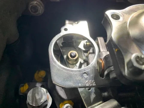
You are right, there are indeed errors in the manual, but your information was helpful in getting me to make the correct measurements. Thank you!!! I found the problem ... Those who overhauled the injection pump had incorrectly mounted the TPS (trohtle position sensor) which was not pulled by the peg you see in the photo ... The rheostat spring with the engine at idle must be compressed and then accelerating she extends .... RIGHT ??? Anyway then I accelerated everything and I adjusted the position in order to have 0,96V following the procedure you mentioned ... Now the automatic transmission works correctly.Applying 5v between VA (Not VC) and E2 and measuring voltage between VC (Not VA) and E2 @ full throttle with the TPS adjustable range slot approximately in the middle and with screws slightly loosened you should be able to then move the TPS to achieve 0.96v as per the manual.
The other test is the linear 1v to 8v steps through the throttle range at the diagnostic port terminals as per below. However I found this to be a little inconsistent even with a new TPS installed.
There is a lot of information in this manual however I have found some subtle errors send you down the wrong path when looking for a conclusion with confidence...........
I take advantage of your experience to ask you something:
a) if I want to have the gearbox slightly more responsive to the accelerator (always maintaining smoothness), in the sense that it only shifts a little earlier, what should I do?
b) By doing these jobs I broke the connector wire hooked to the switch that turns off the air conditioning in case of high temperature (the switch is 89428-36030) ... The switch is ok, the plastic connector is also ok, but I am missing the female PIN to insert into the connector ... I can't retrieve the toyota number .. Can you help me? Thank you !!!
... and if you come to Northern Italy you can be my guest (I live 100 km from Venice)
Attachments

Great info in here, I think my TPS could stand to be adjusted as well and I had been unable to figure out how previously. Thanks to @Magiwirup for the corrections to the FSM!
You are right, there are indeed errors in the manual, but your information was helpful in getting me to make the correct measurements. Thank you!!! I found the problem ... Those who overhauled the injection pump had incorrectly mounted the TPS (trohtle position sensor) which was not pulled by the peg you see in the photo ... The rheostat spring with the engine at idle must be compressed and then accelerating she extends .... Right ??? Anyway then I accelerated everything and I adjusted the position in order to have 0.96V following the procedure you mentioned ... Now the automatic transmission works correctly.
I take advantage of your experience to ask you something:
a) if I want to have the gearbox slightly more responsive to the accelerator (always maintaining smoothness), in the sense that it only shifts a little earlier, what should I do?
b) By doing these jobs I broke the connector wire hooked to the switch that turns off the air conditioning in case of high temperature (the switch is 89428-36030) ... The switch is ok, the plastic connector is also ok, but I am missing the female PIN to insert into the connector ... I can't retrieve the toyota number .. Can you help me? Thank you !!!
... and if you come to Northern Italy you can be my guest (I live 100 km from Venice)
Good to hear.Great info in here, I think my TPS could stand to be adjusted as well and I had been unable to figure out how previously. Thanks to @Magiwirup for the corrections to the FSM!
Riccardo,You are right, there are indeed errors in the manual, but your information was helpful in getting me to make the correct measurements. Thank you!!! I found the problem ... Those who overhauled the injection pump had incorrectly mounted the TPS (trohtle position sensor) which was not pulled by the peg you see in the photo ... The rheostat spring with the engine at idle must be compressed and then accelerating she extends .... RIGHT ??? Anyway then I accelerated everything and I adjusted the position in order to have 0,96V following the procedure you mentioned ... Now the automatic transmission works correctly.
I take advantage of your experience to ask you something:
a) if I want to have the gearbox slightly more responsive to the accelerator (always maintaining smoothness), in the sense that it only shifts a little earlier, what should I do?
b) By doing these jobs I broke the connector wire hooked to the switch that turns off the air conditioning in case of high temperature (the switch is 89428-36030) ... The switch is ok, the plastic connector is also ok, but I am missing the female PIN to insert into the connector ... I can't retrieve the toyota number .. Can you help me? Thank you !!!
... and if you come to Northern Italy you can be my guest (I live 100 km from Venice)
Pleased to hear you have sorted your issue. I have read someone having success of more preferred shifting by setting TPS @ full throttle to 0.75v instead of 0.96v?? Some also increase throttle pressure with the cable setting. I tend to lean towards OEM recommendations. In Australia reliability is vital for outback travel which I do a bit of. I believe in the Modification and Reliability don't like one another thinking
As for the switch part # I am not sure. You would most likely would have to purchase more than you require anyway so you might have to MacGyver something up.
Thanks for the invite, you never know. I was in Venice for a week in 2015!!
Cheers.
Waking up a 2-year sleeping thread..Applying 5v between VA (Not VC) and E2 and measuring voltage between VC (Not VA) and E2 @ full throttle with the TPS adjustable range slot approximately in the middle and with screws slightly loosened you should be able to then move the TPS to achieve 0.96v as per the manual.
The other test is the linear 1v to 8v steps through the throttle range at the diagnostic port terminals as per below. However I found this to be a little inconsistent even with a new TPS installed.
There is a lot of information in this manual however I have found some subtle errors send you down the wrong path when looking for a conclusion with confidence.
I am chasing an inconsistent shift change with no electronic or mechanical faults obviously indicated. My transmission is 24 years old though with 420k's on it. I am suspecting a possible lock-up clutch issue (delaminating friction plates from age) but not committed at this point.
I will say the 80 series 1HD FT/Auto are a great vehicle though.
View attachment 2706906
TT TERMINAL VOLTAGE INSPECTION
1. INSPECT THROTTLE POSITION SENSOR SIGNAL
(a) Turn the ignition switch to ON. Do not start the engine.
(b) Connect a voltmeter to check connector terminals TT and
(c) While slowly depressing the accelerator pedal, check that
TT terminal voltage rises in sequence.
If the voltage does not change in proportion to the throttle
opening angle, there is a malfunction in the throttle
position sensor or circuit.
(Note below Tt indication is incorrect, it is one terminal to the left)
View attachment 2706917
View attachment 2706916
The comment from @Magiwirup regarding the discrepancy in wiring labeling of VC and VA in the transmission FSM is confirmed by the 1HZ, 1HD-T, 1HD-FTE Engine FSM RM617E. Page FU-108 and 109 show the following:
Just for clarification, the two FSM screen shots in two of the above posts state different voltage at full throttle. One says 0.62 volts and the other states 0.96 volts. Can someone explain why the difference? Thanks
There seems to be an error in the manuals. I used the .62V to set my new TPS. A little later, I bumped it up to .75V and had better shifting.Just for clarification, the two FSM screen shots in two of the above posts state different voltage at full throttle. One says 0.62 volts and the other states 0.96 volts. Can someone explain why the difference? Thanks