Builds Here we go (FJ-40 getting a 3B/Turbo/H55f)... (2 Viewers)

This site may earn a commission from merchant affiliate
links, including eBay, Amazon, Skimlinks, and others.

Then we installed the rear brake wheel cylinders, shoes, and all of the junk that goes with that... Yes. Those are new cylinders, and new shoes. I like that you get new bolts when you buy the new wheel cylinders.
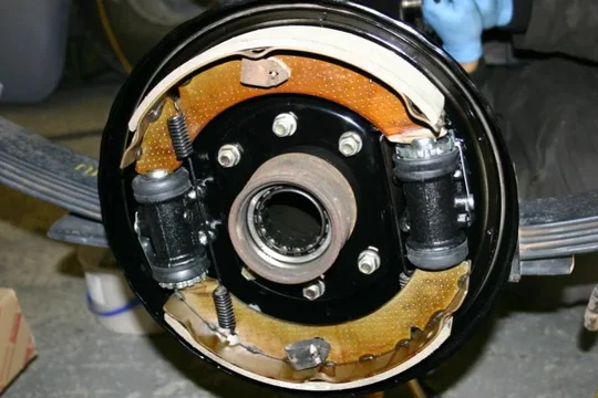
rear brakes 1.jpg

Yes I realize that the axle seal is not installed yet. We've a little bit of work to do before we can put the rear diff back in, so the axle shafts don't need to go in there just yet. If I make good time tomorrow, perhaps I can get that done tomorrow.

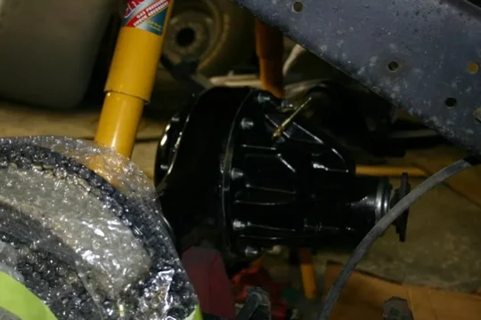
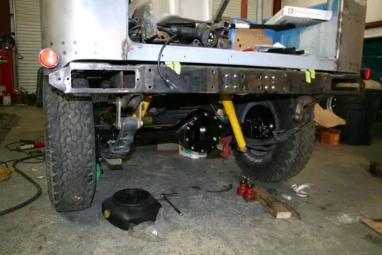
But we did install the front diff. I decided just to use the RTV, and leave the paper gasket out, as I did the same on the faux lux and 60,000+ miles later not a single drip. Also, it should be a lot easier to clean the surface next time we open it up.
front diff 1.jpg
front diff 2.jpg

You can also see some of those fancy new stainless brake lines. They REALLY, REALLY look good in person. I will absolutely invest in the same for my 45 if I can.

OK, tomorrow I'm hoping to put the front back together and on the ground, and with any luck get the rear end back together again. We'll see...

Dan

PS--HJ47th: THIS is the reason my 45 is very quiet at the moment. It's next.
rear brakes 1.jpg
front diff 1.jpg
front diff 2.jpg
 
OK, so quick update on what we got done the next day (on the 20th)...

First, I reinstalled the birfields and whatnot to put the front end back together. Beautiful! I also realized that I didn't have as much bearing grease as I had hoped, so I had to delay putting the wheels back on until I get home tomorrow perhaps. C'est la vie.

front axle.jpg

We also removed all the studs from the rear axle housing (some were damaged, one had pulled out...) and resintalled brand new studs from CDan front and rear of the housing. That done, we put the third member back into the rear axle.
rear axle 1.jpg
rear axle 2.jpg

Looks sexy, don't you think?

The only problem I've run into is that the C-clips don't fit with the ARB. With the axle shafts pushed all the way in, I just couldn't get one to fit. Should I be reusing the C-clips that I took out of there (that match the axle), or some of the thinner clips that come with the ARB. Even the thinnest ARB supplied C-clips don't fit in there. Is it acceptable to grind the C-clips down to fit? I'm simply putting the alxe in, and then trying to slide the C-clip in there the same way they came out. Am I missing something? Is there a technique to getting the C-clip to fit in there with the ARB that I'm missing?

Dan
front axle.jpg
rear axle 1.jpg
rear axle 2.jpg
 
Well, I got the C-clip issue in the back figured out, so that's off the list now. The rear axle looks AWESOME all buttoned up. Yep: all new hardware. Studs, nuts, washers, brake lines.... (I haven't installed the new SS brake lines on the rear yet)
rear axle.jpg

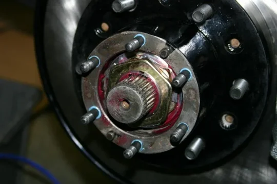
And then I buttoned up the front wheels. New wheel bearings? Of course. New hub nuts and star washers? Would you expect something different? Mobil 1 full synthetic bearing grease? Goes without saying.

Man is it nice to see it all coming together nicely. The V6 calipers required just a touch of grinding, but not as much as I expected.
hubs 1.jpg

I rebuilt this set of hubs for Dad two years ago or so, and they still look awesome (I didn't even clean them up in this picture).
hubs 2.jpg
rear axle.jpg
hubs 1.jpg
hubs 2.jpg
 
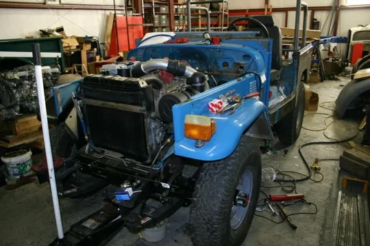
Not that this is anything you haven't seen before, but it's on it's own wheels again. Honest!
on its wheels.jpg

ALL that remains for the axles is to align the wheels in the front. That's IT. The springs will be unbolted from the frame soon to paint the frame, but the axles are done. As in: off the list.

When I get home next week my goal is to wire the starter and glow plugs, fill the engine with water (and some radiator flush) and let the thing idle. A lot. I want it up to temperature both to get a better idea of what we've got here, and to clean it out real well before I pull the engine and strip it down for paint (and things like a new water pump...).

My schedule at work has gotten worse, so I have been moving slower than I'd like, but fingers crossed that I will get some more time in February and March.

Dan
on its wheels.jpg
 
All in good time, and it is looking very nice. Best of luck with it.
 
never get in a hurry at the end, it took this long and a few extra weeks will not make any difference in the long term
but
rushing the final project and you will regret it later.

looking good, congrats.
 
Update time!!!

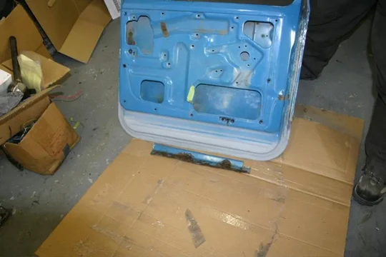
OK, so first things first: dad patched the rust in one of the doors. I'll almost guarantee that I'll forget which door it is that he patched within a year or two. That's how good it came out. Here it is, along with the cut out bit of rusty metal.
door 1.jpg
door 2.jpg

Oh, and the Roundeyes showed up... I can't wait to see them installed and lighting up the road...
roundeyes.jpg
door 1.jpg
door 2.jpg
roundeyes.jpg
 
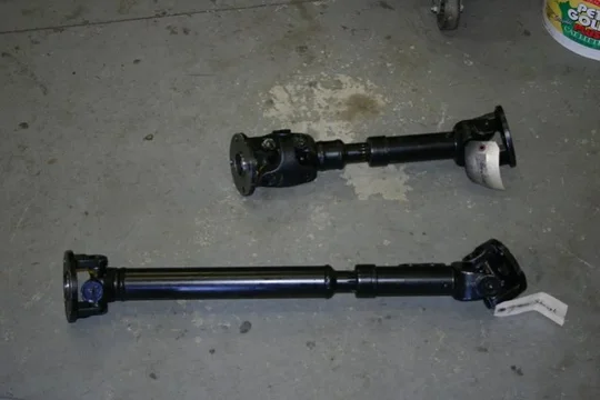
So, we ordered custom driveshafts from Tom Woods (the shop advertised in TT). They came out great. I still haven't put the parking brake onto the T-case, but I did measure all the bits to get the rear driveshaft correct for that. At this point, I'm 99% sure I did it right, but the proof will be when it all bolts together... The front, however, is absolutely correct. We also ordered the Marlin triple drilled flanges for the differentials, just so we could use 60 series ends on both ends of the shafts, both at the T-case and the diffs.
driveshafts.jpg

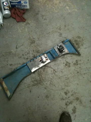
Then I got back to work fabricating little odds and ends. One of the things I wanted was to have a large thermal, resettable circuit breaker coming straight off the battery to then attach the wiring harness (and it's fusible link to), as well as the auxiliary fuse box (through a heavy duty circuit breaker). So, I welded some sheet on the inside of the right apron to attach them (yes, those are captive nuts back there, I'm anal retentive about that kind of stuff).
right apron 1.jpg
right apron 2.jpg
driveshafts.jpg
right apron 1.jpg
right apron 2.jpg
 
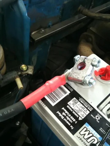
I then made up a battery cable for the starter. It's OO gauge welding cable (which is MUCH more flexible than standard wire), with the solder filled terminals. I'm glad you mentioned them Wayne, I like these a LOT more than the crimped terminals I have used in the past. Here's the overall cable run (I will add some clamps to support the cable, I'm just using that clamp because it's convenient).
battery cable 1.jpg

And here's a closeup of the battery terminal end. I don't like bright red cable, so I just used red heat shrink tubing to indicate that this is off of the + terminal of the battery.
battery cable 2.jpg

Moving on, I went ahead and mounted the glow plug relay. I bought it from NAPA, it's from their catalog as a "glow plug relay," so it should be up to the task. IIRC, it's for a Ford diesel pickup or somesuch.
glow plug relay.jpg

I would use the 2 gauge cable I have to run a cable from the terminal on the starter to the GP relay and to the GPs, but frankly I want to use 2 gauge welding cable instead of the comparatively stiff stuff I bought earlier. Looks like I've got an order to get into McMaster-Carr again...
battery cable 1.jpg
battery cable 2.jpg
glow plug relay.jpg
 
Last pictures for now.

I finished up the radiator hoses. One of the T-stat housing bolts had stripped out, so somebody had drilled out the T-stat housing and used the next size bolt. But we bought a new T-stat housing (without the cap), and I didn't want to drill it out oversize. So I put in a 8mmx1.25 threaded insert so that the correct bolt would again go back in there. No fancy pictures of that, but it worked just find.

Once the T-stat housing was installed, I bolted the radiator hoses on the bottom into place, and trimmed the upper radiator hose to fit. Like a glove! This engine is pretty much ready to fill with water (and radiator flush) to let it run and get up to temperature and clean everything out. I have to plug the heater hoses to do that, but that's easy. Hopefully next weekend I can finish wiring it up enough to get it running in the frame so I can get that done.
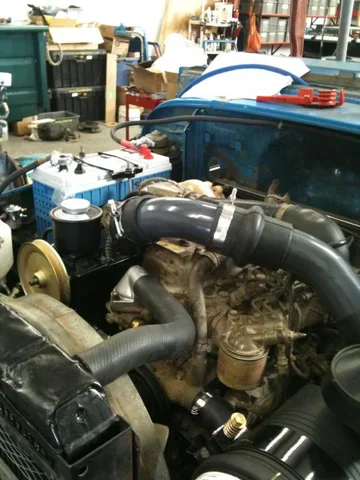
overview.jpg

You can also see that I powdercoated the intake pipes battleship gray, and this time I even used the T-clamps to clamp the intake pipes together. I must be getting serious about running this thing, eh?

Well, that's it for now. My schedule at work is AWFUL for playing with cruisers, so I'm only getting a day and a half at home, and I've got to fit laundry and whatnot into that too, so my time is pretty limited lately. I did find out that I need to remake my PS hose in the front, as the PS line and the bib are trying to occupy the same space. The bib wins, so I need to make a new PS return line (the one in the front here) so that the bib can close AND the PS lines work.
PS line.jpg

I may not get much time to work on it lately, but I am making good progress when I do!

Dan
overview.jpg
PS line.jpg
 
Sweet build! For the steering damper, I used a 60 series damper and bracket, I cut off the original 45 series bracket. Works much better.:)
 
keep up the good work and the updates.

<gets frustrating as the time gets gobbled up, eh?>
 
The frustrating part is that I get a TON done when I get to the truck. It's the stupid job making me spend all this time away (it shouldn't be this bad for long, but this few months sure are sucking).

Wayne: what do you use for fuel line? I need to make a fuel line from the fuel tank, to the Racor filter, and I obviously prefer to make it out of hard line, using shorter bits of Viton fuel hose (yeah, I still need to order that). Since I can't put the bubble flares on the lines that Toyota is so fond of (and I can't find anyone in town who can), should I just bend the metal line and clamp to it (it's super low pressure, suction even), braze on a JIC fitting to then screw on a barb fitting, flare it so I can bolt on a barb, or something else? I have some of the 3/8" hydraulic line, and I imagine it would flow enough fuel for the 3B, but maybe not.... ???

Dan
 
you can use SS or just regular old steel lines, i use the regular since it seems easier to work with and once painted it should last a long long time.
stock size is fine, we are not running race engines.
as long as you allow for movement of the engine then you will be fine with the steel lines close to the pump.

it sucks how work gets in the way of life, eh?
 
I had a similar issue with the hard fuel line - I needed a short length from the fuel tank to the chassis. I used some 5/16" teflon-coated stuff that the local auto parts place had. It was in the same section and rack of the store as the brake line, but i can't remember if it was actually sold as brake line or what it was. Anyway, the 5/16" (.3125') size is hair smaller than the stock 9mm (.354") pipe, and was hand-bendable no problem.

I simply clamped the flex hose to the end of the pipe, with no flare or special fitting. It has held up just fine now for over the past year and a half. I did all that because the original piece of hard line went missing in my pile of parts, and of course, once I had finished putting the replacement piece in, I then found the original. :whoops:
 
you have to remember that the fuel system in an older Toyota diesel low pressure. this does make a difference to the approach of the installation and materials.
 
Man! Nearly a month since I got any real work done on the 40...

That changed today though. I remade a PS line (the other one I made interfered with the front bib), and I made up the battery cables and got my little auxiliary starting panel done. By that I mean I actually wired it up so that I can make the starter spin and the glow plugs glow.

And with that...
YouTube - 3B/turbo startup

That's just a taste. I was worried it might get well below freezing tonight, so I didn't want to fill the engine with water, but tomorrow I'm filling it with water and radiator flush, and I'm going let this thing idle and get up to temperature.

The big project for tomorrow is to let it idle and get warm to both clean out the insides of the water passages, and to get a better idea of the health of the engine. After that, I'm going to get cracking on wiring up the EDIC system and plumbing the clutch cylinders. I'll also see if CDan has any pinion nuts in stock, because if he does I'm going to replace the pinion seals (with Marlin HD seals), and replace the pinion flanges with the fancy pants new ones (with the 60 series pattern on them), and MAYBE even connect the front drive shaft (no brakes though, so I won't be driving it around--much). I've only got two more days to work on it, and then I'll be too busy for another couple of weeks, but I'm pretty sure I can get it wired and able to drive if I really wanted (I don't really, but I could--I think).

Dan
 
So, today I filled it with water (and radiator flush) and let it run a long time. Probably 2-3 hours total running today. Got the thermostat at least a little bit of a workout after the roughly 2 years it has sat.

I also hooked up the Power Steering pump and my newly fabricated PS lines. So far I'm liking what I see. It's not as light as another 60 series PS 40 I have driven (which is good, I thought that one was too light), but it's a one hand affair to turn the wheels--you can see it in the video.

Just to make sure I didn't do something really silly like keep running if it ran out of oil or the oil pump failed I hooked up the horn through the EDIC low oil pressure switch, so the horn honks when there's no pressure. At the end of the video (when I shut it off) you can hear it.

Other than that, I think you're right Wayne: it seems pretty healthy. Now that it's been up to temperature it starts right up, no smoke to speak of (less than my 2LT-E even), and it sure seems healthy all around. It'll be a shame to pull the accessories off the engine just so that we can paint it, but c'est la vie...

Enough typing: here's the video:
YouTube - 3B/Turbo running at temperature

I bought a simple fuse box from a local speed shop (Keep It Clean Wiring :: Home Page), so I added another bracket to the right apron for that.
fuse box 1.jpg

It has two inputs, so I will have an IGN switched side, and an always hot side for those. Mostly I wanted to add a fuse box for the additional gauge pod I'll fabricate (maybe tomorrow), for the headlights (so I can make a headlight harness and have them just about right off the battery), for the fuel heater, etc...
fuse box 2.jpg

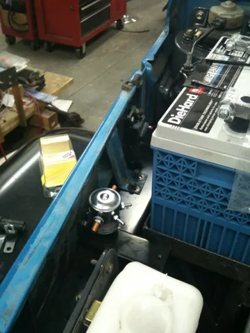
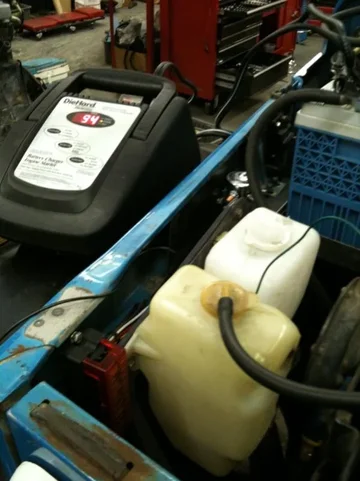
Here you can see the whole right apron. From front to back is the fuse box, the heavy solenoid (for a switched IGN source), and a heavy duty circuit breaker. Sorry for the bad pic, my good camera is up in Colorado with the faux-lux playing in the snow...

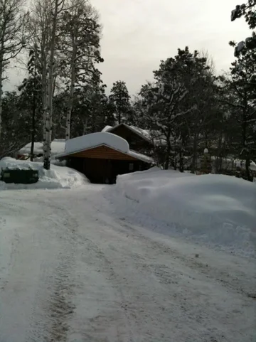
I've been busy between work and play, last week I was here:
snow.jpg boarding for a few days, which explains why the faux-lux is farther north right now with my good camera.

Tomorrow the big job is to set the wiring harness back in the truck and get to actually wiring the EDIC, glow plugs, and additional gauges. At least, that's my plan.

Dan
fuse box 1.jpg
fuse box 2.jpg
snow.jpg
 

Users who are viewing this thread

Back
Top Bottom