Builds 1979 FJ40 Preservation-ish Project (1 Viewer)

This site may earn a commission from merchant affiliate
links, including eBay, Amazon, Skimlinks, and others.

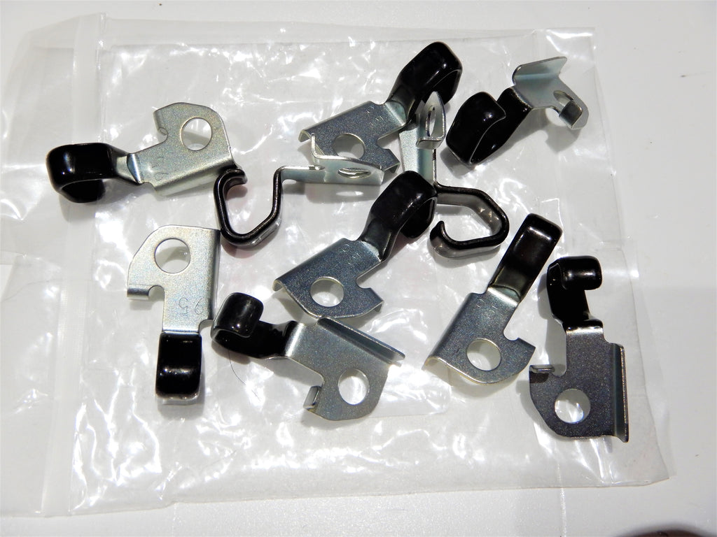
As far as the spider goes, I'd replace them both at the same time and use all new hardware; bolts, washers and nuts.

I cheaped out and reused the old hardware the last time I replaced the u-joints. It didn't hold torque and finally let go and my rear drive shaft fell off!

I'd take it to a drive line shop to check for runout and balance too
 
Last edited:
What are you guys and gals using to secure the hard brake tube to the rear axle?

Toyota P/N: 90480-08343 is discontinued
View attachment 3011770
You could probably use two separate rubber bushings/grommets for the rear brake line bracket.

I think two small bushings, similar to the spring eye bushings, placed end to end from either side of the bracket, might be a good solution if you can't find the actual one.

Maybe @ToyotaMatt could reproduce this bushing???


Problem Solvers These Are ..........

OEM Genuine TOYOTA NipponDenso JAPAN they is :cool:


1652969482917.png

1652969498517.png
 
Going to take that recommendation and replace the spider gears.

I am looking for a grommet to hold the brake tube in the bracket that was spot welded to the axle house and diff cover.
AF2CED3A-2D57-4FC2-BB36-0B252E64D998.jpeg
 
Going to take that recommendation and replace the spider gears.

I am looking for a grommet to hold the brake tube in the bracket that was spot welded to the axle house and diff cover.
View attachment 3012798
I still have original on mine.
I could measure it for you to see if you can rig something together.
9E1C7874-2C5B-4537-95A5-B2315D85EF41.jpeg
 
Following up on some unfinished business with the transfer case.

I pulled the t-case drum brake off yesterday. I have a 10 spline output shaft with 60mm x 68.5mm stud pattern that belongs to a 1/74 to 7/78 t-case. So my transfer case has obviously been replaced at some point.

Diagram: Cruiser Outfitters

Cruiser Outfitters 1 74 -7 78.PNG

Still cant explanation for my (5x18) speedometer driven gear. My truck should/did come originally with a (6 x 16) driven gear.
output shaft removal.jpg

output.jpg


Anyways doing the double seal mod on the speedometer housing.
speedo hoursing.jpg
 
I have been trying to figure out a decent way to blast and paint a 3rd member without taking the diff completely apart.

I cut a hole in the bottom of a buddies crawfish pot. The plan was to paint one side and bath the gear side in oil.

83D9339B-42FA-4725-A712-78F835AFBD4D.jpeg


Apparently you can’t replace the pinion seal without taking the 3rd apart. If I take the 3rd apart I might as well add an Auburn LSD…. if I can find one.
 
I have been trying to figure out a decent way to blast and paint a 3rd member without taking the diff completely apart.

I cut a hole in the bottom of a buddies crawfish pot. The plan was to paint one side and bath the gear side in oil.

View attachment 3082681

Apparently you can’t replace the pinion seal without taking the 3rd apart. If I take the 3rd apart I might as well add an Auburn LSD…. if I can find one.

I think you’re technically supposed to recheck the gear backlash and replace the crush washer/sleeve. I replaced my pinion seal on my 79 and I just gave it an extra ugga dugga with the torque wrench haha
 
You have to take off the pinion nut and flange to do it. There’s no risk of pinion depth changing but the pinion bearing preload can. You can’t accurately measure the pinion preload with the ring gear and carrier in place, so you have to basically go by feel.
 
It's best to measure the rolling resistance b4 disassembly. I would also count the # of turns to loosen the nut if it has a crush sleeve..
 
I am going to to take a chance on just replacing the pinion seal on the front diff housing. I painted the diff housing with POR15 after blasting.
front diff - POR15.jpg


The rear is going to get the full treatment with an Auburn Grip-N-Loc LSD P/N: 546030.
 

Users who are viewing this thread

Back
Top Bottom