elocker wiring and switches

This site may earn a commission from merchant affiliate
links, including eBay, Amazon, Skimlinks, and others.

WarDamnEagle

SILVER Star
Joined
May 20, 2007
Threads
192
Messages
8,499
Location
Auburn
I think I've read ever elocker retrofit thread here and on Pirate and everywhere in between. I want to regear my '85 4Runner to 4.56 and am considering using the factory TRD lockers front and rear as you can buy them new with 4.56 gearing. For $900 +/- per differential, it hardly seems worth regearing my existing open differentials (of course you still have to make the axle mods but they look pretty easy).

Apologies for the preamble as I really just have a question about switches. I've seen a few use the single 4Runner push factory switch when they only have the rear locker (although I suppose you could use both of these). All the other switches that I've seen are generally just metal, two position switches (with various LED light combos).

Has anyone done their retrofit wiring with the turn type switch out of an 80 with factory lockers? If so, anything to be concerned about? I think you would have to use relays as the switch probably isn't rated for the current but it seems like it would be a nice clean install and doesn't look prone to accidentally actuating (judging by the set-up in my 80 and 100 which both have this switch). I would probably still add a couple of small LEDs beside the switch to indicate locked.

The only downside I can see is that you would't be able to lock the front independently. You would only be able to lock the rear or both but that doesn't seem like it would be a problem.
 
I was under the impression that the Toyota locker ran as a closed loop circuit (needs to send feedback to a controller, not just a hot wire). It may need the locker ECU from a donor truck. When I saw an 80 switch removed it looked like it only had 3 connections. The switch could be mechanically designed to make you lock the rear first. If you can part with the factory switch running the lockers independently seems possible. I wanted a T100 rear w/factory locker and found this grainy picture in my search. I think the unused connections were meant for the front diff. Sorry this picture sucks, gotta squint to read it.

Also, don't the housings need modifications for the locker actuators? I was gunning for a complete T100 axle for that reason.
LW1.webp
 
You don't have to use the ECU. Yes, the axles have to be modified but it looks pretty easy. Here are some good write-ups:

E-locker
Retrofit Electric Locker
Toyota Electric Locker

One of these write-ups is a retrofit into a Tacoma. If I was installing it into a model that came with the factory elocker as an option then I would go with the ECU controller. Otherwise, I don't think that it will add anything.
 
I was hoping Mike (foxfab) would post up.

I prefer having separate switches, with lights for locked and unlocked:

LockerSwitches.jpg


I also wired my own relay box, mine lives under the shelf in the back of my Xcab:

LockerBox.jpg


The ECU that they put in the Taco/4Runner will only run one locker. You can also get one for the FZJ80, it will run both. But, those things are unobtanium in the junkyards, and a new one from Toyota is mucho $$$, like around $300 last I knew. Not worth it.
 
Thanks KLF. I had those photos referenced. You do great wiring!

Did you go TRD rear and Hi Pinion front? If so, any difference in the axle modifications? It looks like they are interchangable. I'm not sure the extra money for the hi pinion is worth it as I would need to regear to 4.56.....unless someone has one for sale used.
 
Yes, I have hi-pinion in the front and Taco/TRD in the rear. No, they are not interchangable. The housing mods are the same, but they are not identical. They are a mirror image of each other, very slight differences between the new stud locations and the location of the notch that you have to cut.

Here, this is a link to a diagram I made of the gasket for the front hi-pinion locker:

http://www.yankeetoys.org/documents/FZJ80_HiPinionGasket.pdf

If you print 2 of these (you'll need a tabloid-sized printer to be able to print it full-sized), then flip one over and lay them on top of each other on a light table, you'll see the minor differences.

I really like how the hi-pinion fits, my front driveshaft is almost level. No issues with extreme U-joint angles. I can drive 55-60 mph with the front hubs locked, no vibrations.

Here's another write-up of a retrofit, I took all the photos: Outdoor Recreation Network - Off-Highway, Jeep, & 4x4 Fun
 
Last edited:
Yeah, but that only does ONE diff.

Control%20Kit.JPG

(image stolen directly from the Inchworm site)

I can see why some people would pay for his kit, but IMO $75 for a bunch of wire and zipties, a switch, a light, and some crimps is crazy. Plus, it doesn't include the harness you need to connect to the actuator (unless you cut the connector off and hard-wire it). I probably have less than half of that in my relay box, and it does BOTH diffs.
 
I didnt use a light, its an option. With synthetics in the diffs and not using a resistor in the circuit, my diffs locked up immediately and could easily be felt. No need for a light for me,.
 
You guys do some beautiful electrical work, very informative thread. :cheers:
 
I had 12voltguy make a switch panel and harness for the TRD locker I recently installed in my front end...

e-lock025.jpg


e-lock021.jpg
 
inchworm also offers a diy solution for $75

I have that kit and it works fine for me.

I've looked at that kit and at their diffs, etc. Forgetting about the price for a moment ($150 for two lockers), how does this kit work? I don't see any relays so I assume the voltage goes through the switch. Do you have to turn the switch off when the light comes on? Is it a 3 position switch maybe: lock, neutral and unlock?

I've been meaning to phone them to discuss but living in England most of the year means a very short window to California, especially when you go to bed as early as I do!
 
I didnt use a light, its an option. With synthetics in the diffs and not using a resistor in the circuit, my diffs locked up immediately and could easily be felt. No need for a light for me,.

switch01.jpg


Mike,

In your circuit diagram, I assume you just replicated the diagram for the other locker and used one pole of this 80 switch for the front and one for the back. I also assume it would be very simple to have two diode lights adjacent to the locker switch which would light up when the rear and front locks, respectively?

I agree with you that you don't need the lights but as long as I'm going to this much trouble....

Thanks again. Great help!
 
I've looked at that kit and at their diffs, etc. Forgetting about the price for a moment ($150 for two lockers), how does this kit work? I don't see any relays so I assume the voltage goes through the switch. Do you have to turn the switch off when the light comes on? Is it a 3 position switch maybe: lock, neutral and unlock?

It is possible to wire the locker actuator without any relays, and that's what his kit does. Many have done it without issues, so I guess it's safe.

The actuator has a set of limit switches in it, and a big coil spring. When you hit the switch to lock or unlock the diff, the motor really only torques up the spring, which tries to spin the gear that moves the locking cog in the diff. It's actually a very clever design. It provides for the condition that the cog splines are not in perfect alignment and can't engage. So, the limit switch inside the actuator tells the motor to turn off (so the motor isn't stalled and constantly on, burning it out). The factory wiring (and the relay systems) have a low and high current side of things, the switch on the dash and the limit switch inside the actuator only see low current, just enough to fire the relays (100ma or so), whereas the high current side of the system is the current that goes to the motor, this can get see up to 10A of current if the motor is getting tired or is cold.

The non-relay system like Inchworm sells sends high motor current directly thru the switch on the dash, and the motor limit switches, there is no low current side. I'm sure the dash switch he sells is fine with that much current, but it's the limit switches inside the very expensive actuator that aren't. I just don't think it's a good idea to be sending that much current thru those limit switches, eventually they will burn out.

If you had the actuator in front of you and could pop the cover off, all this would make sense.
 
I also assume it would be very simple to have two diode lights adjacent to the locker switch which would light up when the rear and front locks, respectively?

Yes, it's just a matter of adding a couple of LEDs to the wiring. I really like how the e-locker has this provision via the detector switch right on the diff. If you wire the light in, and that light is on, you are guaranteed to be locked, no guessing (like with an ARB).
 
You'd need one of these relay setups for each locker. The FJ80 switch is just a combo switch. RR closes one of the prongs, FR/RR closes both prongs. SO theoretically, you could also have it wired to allow the front e-locker to turn on and then both instead of the typical rear ,then both lockers.

Yes, the diodes could easily be added, but to actually read the "locked" switch, you'd need to run wires all the way to the diff for the LED. Too much work for me :)


switch01.jpg


Mike,

In your circuit diagram, I assume you just replicated the diagram for the other locker and used one pole of this 80 switch for the front and one for the back. I also assume it would be very simple to have two diode lights adjacent to the locker switch which would light up when the rear and front locks, respectively?

I agree with you that you don't need the lights but as long as I'm going to this much trouble....

Thanks again. Great help!
 
Just another way to go about the wiring...

My 85 4runner came from the factory with a power antenna. At some point in its life the antenna was replaced with a normal non-power antenna. It's a momentary on switch (on, off, on) so it's perfect for powering the elocker. After a little testing with the volt meter this is what a came up with. The back of the switch has six contacts like ::: . In the image below the contacts that I have drawn are the contacts linked together when the switch is in the designated position.

Powerantannaswitch2.jpg


I ran +12v wire to the two contacts on the switch circled in red. I ran the yellow contact to the lock relay and the green contact to the unlock relay

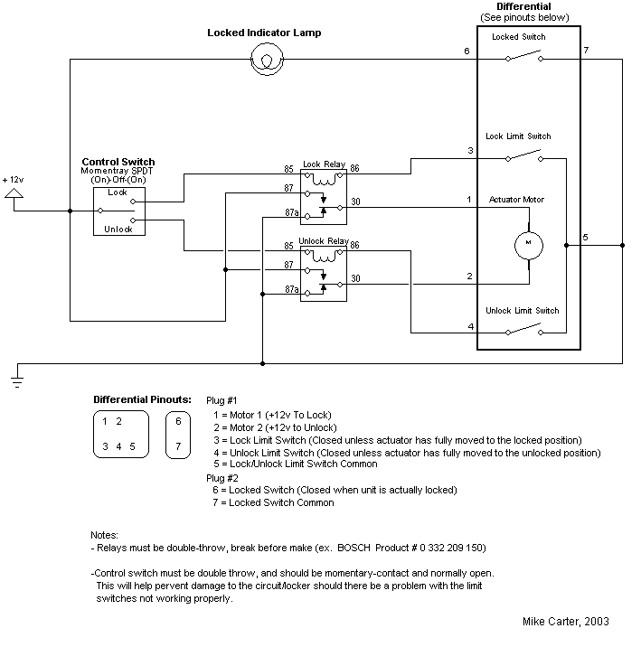
This is the wiring diagram I used to wire up the elocker.

elockerwiring.gif


One of the green LEDs run from the 86 pin on the locked relay then to ground. The LED is illuminated when the locked limit switch is open. This lets me know when I can let off the switch. The other green LED works the same on the unlock relay.

elockerswitch.jpg


The switch only needs to be depressed for about a second to activate or deactivate the locker. So having a momentary on switch has worked out perfect. When I install an e-locker in the front, I plan to get another power antenna switch and place it where the overdrive light is (I have a 5speed so I have no uses for the light). I think most trucks just have a blank punch out instead of the overdrive light.
 

Users who are viewing this thread

Back
Top Bottom