Builds Joel's multipurpose 40 on 41s (1 Viewer)

This site may earn a commission from merchant affiliate
links, including eBay, Amazon, Skimlinks, and others.

I'm having the same space issues of fuel tank
Exhaust with the added bonus of the rad not going to fit up front
The 460 big block Ford takes up a lot of room
Running the exhaust through the boat sides as it's the only place I have too
I wouldn't dump the exhaust down tends to make a dust cloud
I have had the pipes straight out the back tried turn downs ,straight ,and turned to the side always could smell exhaust
Now have them straight to the side In front of rear wheels has seemed the best so far .
I'm going to watch this one because you have many of the same fitment issues I have
 
Wow, been a lot of life has happened since my last round of updates. Biggest news was my parent company closing my office which leaves me in job hunting mode. However since job hunting isn't an all day every day occupation I've also been making great strides on a variety of personal projects including my FJ. I actually hired a welder from the former office (he did give me the buddy rate) so I'm striking while the iron is hot and using a bunch of Steve's time to burn in all my structure.

On to the updates! As I left it, I'd just managed to get the Land Cruiser into the garage when I screwed up my XJ and got de-railed by other things.

FJStructure1.JPG


Took some comments about concern over secondary impacts inside the vehicle to heart and did a bit of testing with the kids.

FJStructure2.JPG


FJStructure3.JPG


Yeah, there's definitely tube padding in our future even if I did decided against the side C-pillar to shock bars.

FJStructure4.JPG


Sometime after this test they announced the office closure so I started using every available lunch hour to build the structure I planned to add. I don't personally have a monstro hydraulic bender with a ton of dies.

FJStructure5.jpg


I actually was given about 30-40 partially bent tubes (mostly DOM) in 1.5 and 1.75 that were mis-bent and/or scrap from a work project. It was almost all 0.095 and 0.120 so that saved me a couple hundred bucks at the metal store since I was able to I cut up and re-use so much of it.

Work also had a bad ass mill style tube notcher. Just about every day I was in there with 10 bars or so notching a bit more. Then I'd take them home at night sharpie how much I still needed and do it again the next day.

FJStructure6.jpg


There were just a couple instances where I went too far and got to redo tubing. Triangulating the boat sides was a challenge since the vertical members were already there and it was a combination of tubes and flats to interface too. Where I screwed up I still used the mistake as a template and filled in the missing metal with tape.

FJStructure7.jpg


That tape I transfered to a paper tube to give me a slip over template.

FJStructure8.jpg


Then I could scribe the correct geometry onto my new tube.

FJStructure9.jpg


Worked bitchin and man I did a lot of notching. This catch bin measures maybe 6"x6"x1.5". It was just about full after one lunch session.

FJStructure10.jpg
 
Last edited:
I might as well let the cat out of the bag on another front.

I bought a 416 LS3 stroker for the FJ. I had planned to do incremental upgrades to the 98 LS1 (already had bought some AFR heads) that the cruiser came with but when I ran across this it was a deal I couldn’t pass up. Big happy crates are, well… big and happy.

FJEngine1.jpg


Full specs on the motor if you're interested:

Low mile LS3 stroked to a 416. Less than 1,000 miles on it. Torn down and verified that everything was perfect (AutoFab Maryland)

10:1 Compression
LS3 Block
Callie's Compstar 4" Crank
Callie's Compstar H-Beam Rods
Wiseco Pistons
ARP Main Studs
CCP Stage 4 Blower Cam (240/254 .613/.596 115)
Roll master double timing set
Melling 10296 Oil Pump
L92 Rockers with BTR Trunion Kit
LS7 Lifters
Ported L92 Heads
Manley Stainless Valves
Manly Pushrods
PAC Springs with Titanium Retainers
ARP Head Studs
LS9 Head Gaskets
Supplied as a Long Block complete from valve covers to oil pan
No pulleys, intake, fuel, or spark
24x Reluctor 1x Cam Gear
Includes water pump
Includes block sensors (coolant, cam, knock, crank)
Includes steam tubes

Good stuff all around... Very similar to LME's 416 package, but slightly lower compression ratio. 626HP LS3 Stroker Build - Supersize Me
I might do a milder cam to keep torque high lower in the range. It will stay NA so the blower cam isn't ideal.


So that’s the good news.

…and then a few weeks later I found out I either had to move to Georgia or I’d be out of a job. Great timing! We decided not to move but if something went sideways and we had to liquidate stuff at least I wouldn’t be out a ton and the same thought goes for the work I’ve been doing since.

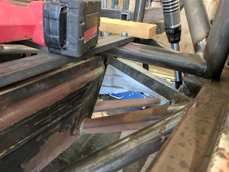
I also picked up a full set of Holley engine accessories figuring that seemed to be the closest of all accessory options I talked about earlier in this thread. I’m optimistic that the new mount will solve my alternator clearance problems. The Holley does in fact mount at a slightly lower angle.

FJaltconflict4.jpg


Compare the straight line off the mounting boss and you can see the difference. I still need to shave the bottom of my front shock mount but I think it’ll get me there.

FJaltconflict5.jpg


So then it was out with the old (sold it to a co-workers at the buddy rate since he let me keep a few pieces I needed)

FJEngine2.jpg


End of the crank had a key adaptor pressed in for my TH400

FJEngine3.jpg


Yummy internals.

FJEngine4.jpg


I did cut myself badly opening up the windage tray holes. Studs on this are large, albeit I’m not sure if that’s an LS3 thing or the ARP hardware. I thought I had enough of a grip on it but the drill snagged and the whole thing tore loose, spun around and clocked me in the thumb. Much blood. Freaked out the kids. Tried not to pass out. That’s what I get for not clamping it down.

FJEngine5.jpg


Finally, in pulling this apart I noted that the torque converter wasn’t actually bolted in. Looks like I’ll need to open up the 3 bolt pattern on the perimeter of the flex plate, but since it all pilots off that center crank extension I think I should be good. Holler if you see a huge flaw in this plan!

FJEngine6.jpg


Color me excited. Now we get into the real work!
 
Last edited:
what do you mean by "the torque converter wasn't bolted in?" they only bolt on the engine side, simply slide in and twist (3 clicks) on the transmission side.

you might like the blower cam - though with the lower compression that could be a deal breaker. Blower cams have more exhaust duration and exhaust lift because any sins on the intake side are solved by the blower. The motor, without the blower, will seem lazy. Changing the cam on an LS is pretty easy... best of all, that cam would sell for decent money - if you're super-lucky, you can get the cam from the motor it's going into. That said, I like that compression ratio - then when you buy old-swill, it'll still run excellent (presuming flat tops and standard head gasket).
 
what do you mean by "the torque converter wasn't bolted in?" they only bolt on the engine side, simply slide in and twist (3 clicks) on the transmission side.

It wasn't bolted to the flexplate. The flexplate bolt pattern will need to be opened up a bit. Not quite following what you mean by clicks, but I'm sure I'll figure it out when I pull that apart.

you might like the blower cam - though with the lower compression that could be a deal breaker. Blower cams have more exhaust duration and exhaust lift because any sins on the intake side are solved by the blower. The motor, without the blower, will seem lazy.

I think the latter half is more likely. I have a 429 ci LS motor in my RX7. By the numbers it's running a tamer cam. I want to say it's something like 235/239 duration, but the motor still lugs below 3000. By 3500 and 4000 rpm it's stupid fast. I'd like to set this up so the torque comes in more like 2000 or 2500. I don't mind it running out of steam at the very top end but I'd like to carry to at least 6000 or so.
 
Last edited:
OK, lets talk structure...

A while back I posted a bunch of masking tape pictures playing with bar placement. I wanted to add a great deal of triangulation as it gives a "proper" load path. Some folks suggested I was overthinking it. That might be true but it's my rig and there were some things I could make so much better with a few key additions that I decided to go for it. I don't mind jumping over some monkey bars to get around.

We started with the rear suspension.

Concept:

StructurePlanning4.jpg


Reality:

Ditched the upper bars having taken the secondary impact discussion to heart. I did make a fully triangulated window to the shock node. The limited lateral/rollover support of the rig was one of my major concerns and this helps.

Burning in the bottom, it's not a perfect node given how the remainder of structure attached already but I'm not worried about it.

FJStructure11.jpg


It's also nice that the lower bar makes another tie between the rockers and frame rails since I effectively have 4 major rectangular bars running fore/aft under the cab. Steve likes to say that anyone can make a beautiful weld on a bench. It's a hell of a lot harder to do so when you're out of position welding overhead while doing some contortionist move. I agree. I've now seen the guy work a pedal with hips, knees, heels flat on the back... It's awesome. Note the left footed pedal action below.

FJStructure12.jpg


And here's the resulting shock traingulation.

FJStructure13.jpg


Not perfect welds but pretty damn good for welding though a window and only able to prop by your elbows. I was certainly happy with all my notching efforts and we didn't have to "make steel" much at all. It's a well supported shock node and that's what counts.

FJStructure14.jpg


-Joel

Structure additions: +4 pieces
 
Last edited:
It wasn't bolted to the flexplate. The flexplate bolt pattern will need to be opened up a bit. Not quite following what you mean by clicks, but I'm sure I'll figure it out when I pull that apart.


I think the latter half is more likely. I have a 429 ci LS motor in my RX7. By the numbers it's running a tamer cam. I want to say it's something like 235/239 duration, but the motor still lugs below 3000. By 3500 and 4000 rpm it's stupid fast. I'd like to set this up so the torque comes in more like 2000 or 2500. I don't mind it running out of steam at the very top end but I'd like to carry to at least 6000 or so.

when you put the torque converter onto the input shaft on the transmission, there are 3 locks that need to engage - so as it pushes all the way in, you'll feel the torque converter go further in in "clicks" as you rotate it.

torque cams tend to be 218-230 @ 050 lift duration and 114* centerline. Stock GM is (varies a lot ) but 208-212 duration and 118* centerline. In something like a light car, 240 duration and 108-112* would be pretty good - but as you said, it wouldn't wake up until there is some port velocity - thus 3000-3500 rpm is the start of the power curve.

This is all very general, but gives you a guideline.

Radical cams - this is funny because it used to be a 108 centerline was radical, but I know of several 101* and 300 degree duration with lifts in the .650 -.750 range. They run really well at 6500 rpm and higher.... below? not so much.
 
Thanks for the kind words. I also appreciate the cam advice. This is my first time playing with the rectangular port LS3 heads, so that's a big difference. One thing I keep coming across are fairly dramatic duration splits for intake vs. exhaust. The longer exhaust duration is supposed to compensate for the relatively lesser flowing exhaust ports. That's not to say they're lazy, be rather than the intake side is that huge. I'm aware that on a bench the intake side pretty much always flows more than exhaust but the ratio of flow has supposedly skewed a bit as GM shifted from Cathedral to Rectangular ports.

Typically I start my cam search with intake open and exhaust close to start from valve overlap and back into the other two events. Lift, ramp rates, LSA, and centerlines I just kinda let be where the cam makers want them to be. If you have all four open and close events you can back calculate most of the others.
 
Last edited:
Boat side triangulation.

Concept:

StructurePlanning2.JPG


Reality:

I did do the basic triangulation. This is all 0.120 wall to let it take a few shots. I'm not really planning to skin this area. I'd rather live with getting hung on a few rocks and have the exhaust see a greater ability to breathe.

FJStructure15.jpg


Front most bar was pretty the easiest since it slides in fine with one end being pure flat.

FJStructure16.jpg


I've been debating with myself whether I should better support the upper control arm support tube. On the on hand I could make it stronger with added support. A big front impact scenario (IE lawn dart) puts that in pure bending. On the other hand, if I took a shot hard enough to bend that front bar, would I have wanted this to act like a crumple zone? If I do brace it further then I'd guess I'd be ripping a wheel off as the failure mode, but that might be easier to repair than frame damage if it bent far enough to pull something else out of line.

Thoughts on added support for the front suspension links are appreciated...

The rear two bars were a great deal harder to cut. Since I was adding the angle inside a window I had to compromise both ends or it couldn't be installed (no way to slip these in place with a full fish mouth on each end). Tricky, but I think I got it. To be fair, this is where the tape and paper tube templates came into play.

FJStructure17.jpg


I get that some folks might not have bothered with this triangulation. Pesonally, I like the fact it will turn each boat side into a space frame (floorboard above will be heavier than normal). I also like the fact it'll give the exhaust a little more protection. Speaking of exhaust:

At some point I had aspirations of trying to make scratch built triangular mufflers and run them down the complete edge.

ExhaustConcept2.jpg


Yeah, not doing that. With the stroker motor I want to be into dual 3s and area under the front foot wells is just too shallow I'd also given up on packaging a rear mount muffler. I need that space for my gas tank. However, I still wanted good flow and relatively quiet so I bought the biggest Magnaflows I thought had a prayer of fitting and decided to let them bulge up toward the seats. I ended up with 6"x18" round cans.

FJExhaust1.jpg


If I pull the rear seat mounting structure up by 1/2" I should be OK. As shown, it's resting on both inner and side rails so the muffler needs to move up a bit. I'll still only have 3/8" on a side but I think I can work with that.

This also put the exit right into a pair of odd looking rectangular bars: one per side I'm assuming from original layout fab. Those had to go.

FJExhaust2.jpg


Usually the angle grinder is my go do destruction tool, but for cutting right next to a rail the sawzall worked better.

FJExhaust3.jpg


I did have to keep dipping the blade in ice water to avoid smoking it (yes I'm aware frosty beverages and power tools don't mix). Turns out these were solid bar so each weighed about as much as one of the boat side tubes I added.

Structure count: +6 boat sides, -2 solid bar.
Net structure added to date: +8 pieces
 
I have to say, their is some awesome fab going on here. That motor is gonna be sweet. For my Sawzall blades I use cutting oil, use the same oil for my drill bits too, seems to make them last longer. My one concern I guess would be weight. I would try to limit how much steel you add. For example on your boat sides, I think it's awesome you put some triangulation in, but I would have limited it to one triangle tube. Which would save you about 20 pounds per side. Reason I say that is that I've noticed a significant difference in how my rig climbs(which mine isn't near as sweet as yours is)if I add or subtract 200 or 300 pounds. With that in mind I'm trying to be careful in adding stuff, especially in the rear.
 
Point taken. I'm trying to be weight conscientious, but still trying to get the load path I'm looking for. All in, I think I'll be adding about 80 lbs of steel in tubing. The boat sides should be about 15 lbs of that net. Even the 0.120 wall 1.75 is only about 2 lbs a foot.

Tubing Strength Chart and weight per foot - Pirate4x4.Com : 4x4 and Off-Road Forum

I will be going a lot lighter on body panels and the like, using aluminum where I can, but I really have no clue what this will weight when done. Could be anywhere between 4500 and 6000 and it wouldn't really surprise me. Just trying to build as efficiently as I can and add horsepower to handle the rest. I am hoping for power to weight kind of like a RZR 1000.
 
Maybe I missed it somewhere but what is the wheelbase on this and what travel are the ORI struts?
 
Wow this is a great build, I can't wait to see this thing driving!

Thanks, I at least have the majority of the design in my head at this point. Pedals and steering are my biggest wildcards remaining.

Maybe I missed it somewhere but what is the wheelbase on this and what travel are the ORI struts?

110" WB, 82" track @ outside of tires. The ORI's are 16" travel on all corners. Likely shooting for about 7" up, 9" down. Comments appreciated.
 
Continuing forward...

Sturcture concept:

StructurePlanning1.JPG


The biggest issue in the engine bay was the shock loading going only into a upper tube and having a long span in pure bending before it tied back to the lower bars via some of the front bumper structure.

I wanted a much more direct load path so I added these vertical kickers from shock towers down after measuring about 10 times that my radiator would fit. The couldn't be as diagonal as I originally taped them but it's still a massive improvement. 0.095 wall here since they should mostly see pure tension.

FJStructure18.jpg


I also noticed that the removable cross bar is a bit tight when I pulled that to yank the motor. That's the reason for the bar clamp pulling the towers inward slightly before welding (removable bar in place, just at the limit of it's travel inward). I'm hopefully any residual stress will be moving things the way I want them.

The bottoms of the new shock tubes are slightly bent so they taper into the lower frame rails. This was partly because I thought it made for a cool/interesting detail that buys me a touch more engine bay space. It was also partly because the steel was free, already had bend, and only long enough legs to do it this way. :)

FJStructure19.jpg


I also added a diagonal kicker from the rockers to frame rails on both side to complete my boat side tie ins.

FJStructure20.jpg


I have not yet added the diagonal tubes downs from shocks to the engine mounts. I need headers built before I could even considering doing that since I'm not sure how much space I need for install/removal. As it is, I'm already much happier with the structure.

The last major structure I'm going to have to do somethign about is the shock towers themselves. The notches ahead of the shock make for some nasty stress risers and it also has a lovely dimple died hole just waiting to greet a crack forming.

FJStructure21.jpg


I'll probably close off the sides but it's going to make for some interesting geometry if I try. We did commit to the shock position and finished most of the topside tig work above. This only had a few stitch welds previous.

-Joel

Structure count: +4 pieces
Net structure added to date: +12 pieces
 
More nice work! I am running the 16 inch ORI's on my custom 4 door build. Only three runs on them so far but I am really happy with them!
 
Nice. What did you set yours for pressure and ride height? Got a link to a build thread or any more detailed reviews?
 
I don't have a build thread, I should really start one! For pressure I started at 90 in the lowers and then added to the top until I get 8 inches of chrome. I followed the instructions the best I could so I could eliminate that as a variable. Down the road if I want to make some compromises with ride height I can but at least I know how it is supposed to feel at mid stroke.
 

Users who are viewing this thread

Back
Top Bottom