Ammeter/fusible-links ......late model 40-series

This site may earn a commission from merchant affiliate
links, including eBay, Amazon, Skimlinks, and others.

You make the meter more sensitive by increasing the shunt resistance. Doubling its length doubles its resistance and doubles the sensitivity of the meter.

Quite true.

And in this context the "shunt resistance" is the "fusible link".

So, in theory, increasing the length of the link wire will achieve the same result as choosing smaller-gauge link wire.

But I believe you'd have to go to ridiculous levels (like having a coil of fusible link wire there) if you were to stick with the same gauge that the factory chose. (I believe it is THAT MUCH oversized.)

And no matter what method you use to increase the resistance (and hence voltage drop) of your monitored fusible link (in order to get good needle-swings on your ammeter), I believe you're still going to create "electrical reliability problems" (by decreasing the supply-voltage to downstream relays etc).

When my link was hanging on by just a few strands - it made my Fuel Control Motor slow to move. This resulted in my engine being slow to turn off and more reluctant to start. (I give this as one example of the harm caused by "reduced downstream voltage".)

:cheers:
 
So isn't there a way to measure the required resistance for the ammeter to function properly- just to check your theory that the voltage drop would be too much for the rest of the system. I just happen to have a new ammeter (24v) on the way that I picked up for a decent price here on auction (hence my hope to make it actually useful...)

Peter
 
I suspect that back in the late seventies there was probably a similar argument/discussion occurring between Toyota electrical engineers.

I suspect the engineer who chose to replace the old "full-current ammeter" with the cheaper "shunt-resistor ammeter" wanted a lighter-gauge fusible link to be fitted to ensure his new ammeter performed properly. However I suspect the more-powerful engineer overseeing wiring loom production over-ruled him because he (and I am not sexist .. could be a she ;)) thought (as I do) that the all-important "reliability aspect" would be compromised by downsizing the link in this way.

Apart from anything else, you never know what a landcruiser owner is going to add in the way of spotlights and other high-current-draw accessories!

I admit that the reliability problem is possibly not as bad as one would think from the way I'm behaving. And I accept that I am probably obsessed with "reliability".

Truth is, while your alternator is running, the voltage being fed to downstream components CANNOT be compromised by any "undersized fusible link" because the alternator "back-feeds" the battery through the fusible link. So while the alternator is running downstream components will actually be getting fed with up to say 14.4V in my case or double that ... 28.8V in the case of your 24V cruiser (from the alternator).

The possible harm (from low downstream voltage) comes when your alternator isn't working which is when
  • it is carput/stuffed, or
  • your engine isn't running (maybe when you're about to start it), or
  • your engine is still revolving but you've just turned your ignition key to "off".
And your fusible link is under maximum stress when
  • you have a flat battery and have just started your engine so all the alternator output is going into charging your flat battery (or flat batteries - plural),
  • whenever it is compromised by corrosion or broken strands,
  • when your engine is off and for some reason you have all your lights on and perhaps have the key in the "motor run" position with the heater on full-bore too etc
  • you've upgraded to a more powerful alternator or fitted spotlights or other high-current accessories (exacerbating the above)
  • etc
And the effects of corrosion (and of metal-fatigue if the wire has any movenent) will be more likely to lead to failure with lighter-gauge link wire nof course.

So to round this up (and if you're really keen to see your new ammeter become useful), I reckon you should experiment with fitting smaller gauge link wire and perhaps carry a made-up spare "fusible link assembly" (as photographed in this thread) in case it ever fails on you.

(Your spare could perhaps incorporate the normal heavier gauge link wire.)

With good knowledge on what you're doing you'll probably succeed and run for at least a decade with a functioning ammeter and with no associated breakdowns/ill-effects.

If you do ... please post up all about it.

:cheers:
 
The external shunt amp meter was introduced for safety reasons: to avoid having more high current wires entering the firewall than necessary. I'm reasonably confident that the meters work accurately. They have a higher current capacity than the earlier units (60A vs 30A full scale). The reason that you don't see it deflect much is because you aren't sinking much current. If you want to see it deflect discharge your battery fully and I will bet it will deflect to the right near full scale. My 30A meter has deflected full scale after winching.
 
The external shunt amp meter was introduced for safety reasons: to avoid having more high current wires entering the firewall than necessary. ....

Yes. I've always suspected this to be the reason for the modification too Charlie.

... I'm reasonably confident that the meters work accurately. ...

I'm glad someone is (because I'm not.) :lol:

....They have a higher current capacity than the earlier units (60A vs 30A full scale). The reason that you don't see it deflect much is because you aren't sinking much current. If you want to see it deflect discharge your battery fully and I will bet it will deflect to the right near full scale. My 30A meter has deflected full scale after winching.

Mine's 50A (not that this makes any difference to your argument).

I don't have an electric winch and my ammeter never moves apart from getting a microscopic twitch when my hazards are turned on. And from what I hear this is a common experience (although I admit most people I talk to own BJ42 models so maybe the petrol FJ40 model has some differences that make its ammeter work better?).

And perhaps I could indeed get my ammeter to move by flattening my battery and then restarting my cruiser somehow.

But IMO ... unless an ammeter is able to show immediately that an alternator has stopped charging - then I think it is just there for cosmetic reasons and serves no useful purpose.

:cheers:
 
But IMO ... unless an ammeter is able to show immediately that an alternator has stopped charging - then I think it is just there for cosmetic reasons and serves no useful purpose.

:cheers:

This is certainly true as its primary purpose is to indicate the charging state. The problem (or benefit) with diesels is that they don't cosume any current when running. If I disconnect the alternator on my petrol version I see about a 7 amp drain with just the engine on.
 
....If I disconnect the alternator on my petrol version I see about a 7 amp drain with just the engine on.

You're lucky! With that meter-sensitivity I wouldn't have bothered fitting a separate voltmeter to mine.

What year is your FJ40 Charlie?

I just went out and turned on my headlights (engine off) and confirmed that my ammeter needle doesn't budge off "zero" AT ALL.

And that headlight current DOES pass through my monitored fusible link (ie - through my ammeter shunt). So this proves how oversized my link is (and how insensitive my ammeter is as a result).

And that "monitored link wire" there now closely matches the one that the factory installed.

And my ammeter has always had this insensitivity problem from the day I bought the cruiser back in 1981... apart from a short period (described in this thread) where I got ammeter-sensitivity because of multiple broken strands (from vibration/metal-fatigue) in the link wire.

Doing the same test (ie. turning on my headlights without my engine running) with my ignition key on "engine run" (which switches on my new voltmeter) shows a small voltage drop on my voltmeter (proving its usefulness).

Actually the new voltmeter is proving to be extremely useful (for showing how well my alternator is performing) because it seems to under-record my battery voltage (showing it as around 11.5V) before my engine is started. And once started, it rises instantly to around 13.5V and then settles around 14V most of the time.

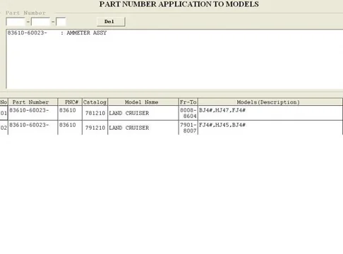
My "-50 to +50 shunt ammeter" is used on petrol models as well as diesels:

ammeter.webp

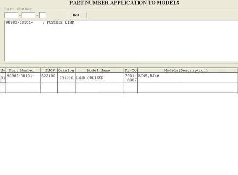
But my fusible link assembly is used only on diesels:

FusibleLinkAssy.webp

But the fact that the link assy is used only on diesels stands to reason just on the fact that the glowplugs would need special consideration (for link sizing). They draw at least 10A each!


:cheers:

PS. My glowplug current doesn't pass through my monitored link. It passes through the OTHER one. (Which is why I still see no reason for these ammeters to be sensitive on petrol models yet insensitive on diesel models.)

Edit....Here's my wiring:
ChargingWiringBJ40.webp
ammeter.webp
FusibleLinkAssy.webp
ChargingWiringBJ40.webp
 
Last edited:
Here is a source for Delphi fusible link wire in service packs. White Products sells the service packs directly. The service packs for 14 thru 20 link gauge have 10 links per service pack.

Fusible Link Wire
 
Bumping this up for some questions about the fusible links on FJ40's 79-83 with the 50A amp meters.

Referring to the pic in Post #25: Is the 79-83 fusible link/amp meter wired this same way with 3 plugs? I realize the fusible link end plugs will be the single pin, but is the amp meter connector the same as the BJ40 shown? A 2 pin female T connector? Also, the twin fuses: Are they located in the same position on the 79-83 FJ40's? Lastly, where it connects to the battery: Was the + connection molded into the battery cable or was it a ring terminal on the lug bolt?
 
Expanding this to include 72-78 with different questions:

Can someone verify the 72 had a fusible link? My schematics from Haynes show that it does, but I need to verify.

Pics of any year OEM non modified fusible links would REALLY help.

Last: From what I can tell all the fusible links for FJ40 72-83 are 14ga (2mm) ? Anyone have info to the contrary?
 
Nice Job on the write up LM,

A bit of trivia on the fus links---the actual fusible link type wire has insulation that will not burn vs regular wire which has insualtion that will melt/burn away

Isn't it (the insulation on the link) suppose to bubble badly so you know it has been sacrificed?
 
Yes, you will have no doubt that it is "fried". The thing about fusible link insulation is it doesn't melt and run exposing the copper wire allowing a short. The copper can melt inside the insulation.

Isn't it (the insulation on the link) suppose to bubble badly so you know it has been sacrificed?
8852DG18.gif
 
Bumping this up for some questions about the fusible links on FJ40's 79-83 with the 50A amp meters.

I hope you get replies Mark because I'm keen to know if anyone has a -50/+50 ammeter that functions properly and what their differences are from my setup.

I can't see why just the diesels of this particular era would have been singled out (by themselves) to be lumbered (by the factory) with this "non-functioning ammeter problem".

.. Was the + connection molded into the battery cable or was it a ring terminal on the lug bolt?

Those blue battery cables of mine are not OEM. ....I fitted them.

And I vaguely remember making up that "ring terminal/lugbolt connection" myself.

But my memory is such that I can't recall for sure what the factory had done. (I suspect those two thick white wires were moulded into the original lead terminal clamp of the original black-coloured +Ve battery cable.

Despite my poor memory, I am pretty certain my original cables had black-coloured insulation and that the original terminal clamps were huge (in comparison to the present ones) and made of lead. (I had to replace them because the softness of the lead ...coupled with over-tightening ...meant that the clamps had deformed to the point where they could no longer clamp my battery terminals effectively.)

Cheers
Tom
 
Mark,

The original positive battery cable on the 1979-up FJ4xs was made with a short length piece of 10 gauge (5.0 mm2) wire molded into the lead clamp--no ring terminal. At the end of this wire was a plastic connector with a single large female push-on terminal. This mates with a matching single male tab in a plastic connector, with crimped side-by-side both a nine inch piece of 14 gauge (2.0 mm2) fusible link wire and a six inch piece of 18 gauge standard white/light blue stripe wire.

The 18 gauge goes to a plastic tee connector along with a three inch piece of black 18 gauge wire. The black 18 gauge wire is attached to a single plastic connector with the other end of the fusible link wire. This single connector mates with a matching single connector to which is attached a 10 gauge white wire w/light blue stripe to feed the vehicle's power.

The 18 gauge wires are the feed wires for the ammeter and run for about 12 inches to the black plastic snap fuse connector with two 5amp fuses, and then on to the ammeter. The two 5amp fuses are the same as in the black plastic snap-box as shown.

All this occurs in the engine compartment. I think this all is the same for a 12volt system--gas or diesel.
 
Bear! You da man! :clap:

All these threads about harness fires and missing fusible links got me to thinking that I should look in to building these.

I ordered some samples of what I think are the correct connectors and have some 14 ga fusible link on the way. If they work I should be able to provide replacement fusible links cheaper than Toyota for the 79-83 FJ40 and could even offer a retrofit kit for the early FJ40. If you have a BJ40 I think I can even get all the connectors to build those as well thanks to Lost Marbles and his excellent write-up. Sorry FJ60 guys but fusible link connectors for you I still have not found. :frown:
 
has anyone produced the (mud) fusible links, i just fried mine and wiould be interested in purchasing a pair. i have a "77" FJ. i went ahead and bought 14 gauge link wire, but am having trouble finding replacement ends, guess i could salvage old, but would really like new. great thread
 
has anyone produced the (mud) fusible links, i just fried mine and wiould be interested in purchasing a pair. i have a "77" FJ. i went ahead and bought 14 gauge link wire, but am having trouble finding replacement ends, guess i could salvage old, but would really like new. great thread

Did you talk to Coolerman? The link is DIRECTLY above your post to his wiring parts for sale (Hint, its in BIG RED LETTERS). Or, you can click here - Untitled Document.

:cheers:
 
my ammeter never moves apart from getting a microscopic twitch when my hazards are turned on. And from what I hear this is a common experience (although I admit most people I talk to own BJ42 models so maybe the petrol FJ40 model has some differences that make its ammeter work better?). :cheers:

Sorry, I stopped following this thread. Maybe your new link has a significantly lower resistance than the old one even though it was the same gauge.

You can make the meter as sensitive as you want. The more you increase the distance between the two meter wires (and increase the total shunt resistance) the more sensitive the meter reads. Move the chassis side meter lead about 50 cm away from the other wire using a needle to pierce the insulation and you will see it deflect. You can find the sweet spot by trial and error.

Good method for working out the "working length" Charlie. :clap: But I guess I should try and summarise my feelings more clearly.

I have no doubt I can tweak the length/diameter of my new fusible link in order to get the same sort of useful needle-deflections I was getting when the old link was hanging on by just one or two strands of wire.

But I think the price I'd pay for doing this would be "reduced reliabilty/performance of the electrical components/loads fed by that link". (This is just the "key drawback" and I've already mentioned other ones too.)

(When the link was hanging on by a few strands I did experience "slow EDIC motor movement" for instance.)

So if there are any owners of late-model forty-series cruisers (petrol or diesel) that are getting good needle movement out of their -50/+50 ammeter (and I can't recall any saying so) - then I suspect their rigs would be suffering from this "reduced reliabily" (whether they are petrol or diesel).

I have electrical trade experience/qualifications from my past life (ie from previous jobs) and I think this helped to convince me that "reduced supply voltage" is harmful to both the performance and lifespan of many electrical loads (like motors and relays).

So I believe "the ideal link sizing for good ammeter movement" WILL cause significant voltage reduction for all downstream loads (like my start relay, glow plug relay, EDIC motor etc). So I've decided I won't go down that path.

Instead I just decided it was better to add a voltmeter to my dash which provides me with useful feedback and has no negative effects (to my knowledge) other than appearance-wise (for being a "non-OEM addition").

:beer:
 
Well I just have to throw this in for the sake of discussion. Tom I totally understand what your point is but- is it not also true that one must actually test the circuit to be sure that the voltage is significantly reduced. Also we must remember that the majority of the current passes thru the fusible link when the engine is off and the alternator is not turning/supplying elec. And at least on my car this means that the only thing that will be getting current solely from the battery thru that fusible link is the starter and edic relay which if not pulling many amps should not cause much of a voltage drop.

Right now my fusible link is blown and in its place is a 20 fuse as a temporary measure. And I have no problems starting and running my vehicle with just a 20 amp fuse. And as I said once its started current will be supplied by the alternator for the headlights, heater fans etc etc. I do have a spare and I will probably go to a 30 amp just to be o the safe side.

Food for thought.

pete
 

Users who are viewing this thread

Back
Top Bottom