Builds Aloha from Las Vegas! 77 FJ40 Project (1 Viewer)

This site may earn a commission from merchant affiliate
links, including eBay, Amazon, Skimlinks, and others.

Lots of good info in @SipLife 's build thread.
Thank you! That is just what I’ve been looking for.
 
Lots of progress today. My plan was to hose down the knuckle parts with brake cleaner and start re-assembly. Instead I went down the rabbit hole of cleaning, painting and shining up the parts to make everything look nice.
While the paint dried, I went ahead and replaced all the tie rod ends with a new 555 set from @cruiseroutfit and rebuilt the center arm and drag link. I’m really curious to see what all new steering parts will feel like.
 
After a long day at work (26 hours), I hooked up my trailer and took a nice drive into the Kansas countryside. Picked up another key piece for the build- a 5.3L Vortec engine from a slightly wrecked 2003 Suburban K1500.
The nice folks at the salvage yard said it ran great and made 40psi oil pressure. Compression was between 160 and 185 on all cylinders. Looking forward to prepping the engine and figuring out how to marry it to the 40.


After I unloaded the engine, I took my new rotors over to @kc_chevota and he opened up the centers to fit the 40 rear axles. Hope I got his good side.

8D55CBB9-A60F-4269-BE12-73DA58A60841.jpeg


4FD8F4B8-CE8E-49E3-B45B-CB41C92A2C02.jpeg
 
This weekend I put the knuckles all back together and assembled the front brakes. Spent the time to do all the knuckle centering measurements and calculations. Everything is in factory spec- steering preload, fasteners torqued. Only upgrade to the knuckle job was the use of Marlin axle seals.
On the brakes I did the usual upgrades- substituted 4Runner calipers and pads, made backing plate eliminators, new hoses that go from frame to caliper. So rewarding to replace the old parts with new, clean painted parts.

0D744DD4-8D0C-4768-A2E6-91EAFC5826C6.jpeg


AC8C4C86-BC77-47F4-89DB-3CC5D6E2D223.jpeg
 
Pulled the rear axles today, cleaned them up and painted the hubs. Replaced the axle seals- bearings were perfect so I left them alone. The diff gears and oil looked like new. Nice to find good news when you open stuff up.
Installed GM metric calipers using @Poser brackets and a bunch of parts from O’Reilly! I did have to grind clearance for the banjo bolts and reduce the hump on one caliper (one had a smaller bump!).
This will be awesome going from single-circuit 4 wheel drum brakes on my ‘65 to power-assisted 4-wheel disc brakes on this build!

38144CDE-3828-42DD-AEB6-BC1F64711CEC.jpeg


43C81950-21BC-4C9D-8350-60EFA5FE13BA.jpeg


47F1BE7B-A4EE-4DCB-97F2-CEF9CF635915.jpeg


639EDDC6-1A66-4895-B1D8-401C37987A26.jpeg
 
I loaded the chassis up on our car hauler and used it to bring the tub and body panels home. Everything is now blasted clean and primed with PPG epoxy.


F54CA682-6977-4A41-9BC4-E2D3289F926C.jpeg
 
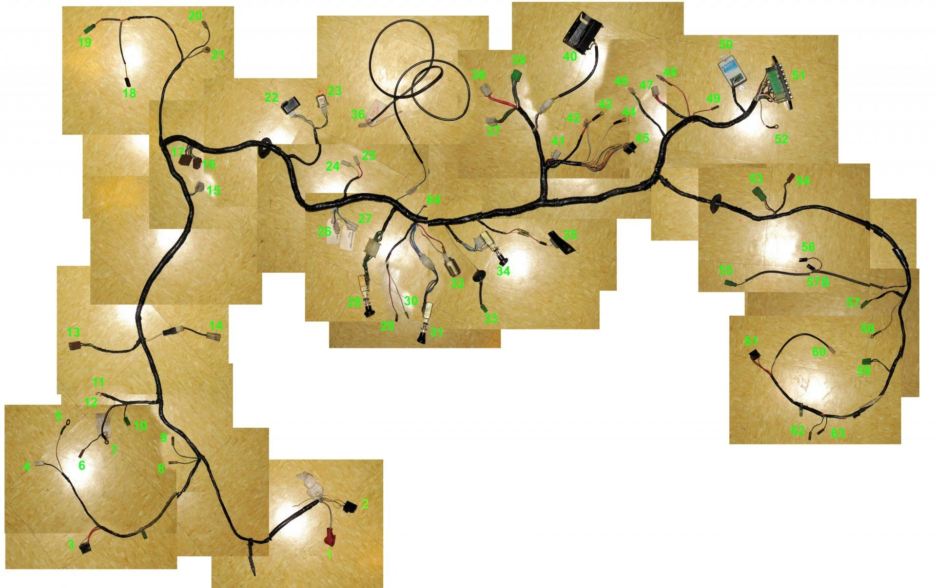
Now that the body is here, I can start working on the electrical system. I cleaned most of the crud off the old harnesses with Pine-sol and Goo-gone, then put them in place and started connecting the switches and plugs. I sort of got carried away and put most of the dash together just so I could see what it would look like!

The harness was mostly in excellent shape, except for a few broken/crumbling plugs. I’ll be ordering some new plugs and a fusible link from @Coolerman .
I spent a few hours identifying and labeling each connector on the harness. Most were familiar to me from my previous 65, but I had to go back and forth between the FSM wiring diagrams, Coolerman’s site, and this extremely helpful post from @woytovich :

AEDA8ED9-2F50-4E78-B598-9F0122A733BF.jpeg


76F9A147-33B1-4B82-B9B3-0BF92077EB2F.jpeg


BCBB0CAA-B830-4E05-B6B0-1508B109C354.jpeg
 
While I wait for the rest of the parts I need for the original harnesses, I thought I’d dig in to the wiring for the transplant engine. Luckily, there’s a website that everyone seems to use to guide them through the process of stripping the OEM harness to use as a standalone.
Brendan’s LT1 Swap site

The original harness before de-pinning amd stripping unneeded circuits:

C319018B-F1B4-4576-ABC7-2D80378261C8.jpeg
 
Still waiting on a few key parts to get the motor and transmission mated. In the meanwhile, I’ve been cleaning and prepping the engine for installation. New valve cover gaskets, front and rear main seals and swapping the oil pan for a Camaro style to get better clearance.
The exciting news is that @orangefj45 shipped my new trans and transfer assembly. I kinda went overboard- it’s a new H55F with a completely rebuilt split transfer case. I opted for the 3:1 low range gear and Georg fitted up the elusive OEM e-brake setup. I also had him include the reproduction shifters and a crossmember for the trans. The 5-speed may be overkill considering I have V8 power planned, but I’m really glad I’ll have a quieter gearset in the transfer.

B1035900-1A13-4E22-AEDB-F3DA45A72B0D.jpeg
 
Thanks to @tornadoalleycruiser for the heads up that I would need to clearance the bellhousing to get it to mate up with the H55F. Just a few minutes with the die grinder and I fit it right up with new hardware.

9AA57875-11F4-4058-8218-AE40B8B47D24.jpeg
 
An unexpected early escape from work today meant I had time to pluck the body up in the air and clean up the frame. I still had a few remnants of the old engine mounts and bell housing mount. This old gal has gone through a 2F and a 350 SBC and will soon have its third engine!

7479FA34-D5F1-4648-8EB1-A4F165CA8127.jpeg


69DC0A44-CB47-4BDB-9F29-D7F14140BA44.jpeg
 
Another major milestone- @kc_chevota came over yesterday and we set the drivetrain in place. The bellhousing bolts from Advance Adapters were much too short and would only grab about 10mm of thread in the block. We cut down some longer bolts I had on hand for now.
I used the Advance Adapters bellhousing and motor mounts and put scab plates on the inner frame rails as recommended by AA.


D89C4C84-231C-44CC-9783-8613DCF5ECE2.jpeg


I had studied as much info as I could from the Advance website and other LS builds here on MUD. I think the engine is situated pretty well. Almost an inch of clearance to the firewall and plenty of room under the hood and between the frame rails. The only tight spot is between the AC compressor bracket and the front diff housing. Only about 3” of clearance as it sits now on the old suspension. I’m seriously considering flipping the springs around to move the axle forward.


4A552DE7-7A3B-4410-883E-A6D6B0E34048.jpeg


The shifter sits nicely in the original opening and that makes me very happy. Plenty of space around the parking brake, so no mods necessary to the frame crossmember back there.


8C3AEF1F-CD0C-49FA-9726-EC8C3FCA8311.jpeg


F1E30FDA-0D44-4F27-838E-E805ED70BA2B.jpeg


5A504C3A-DE11-42C7-B743-A98621DE57EE.jpeg
 
Last edited:
After a little more measuring and head-scratching, I decided the engine and trans were right where I wanted them. The engine mounts were in place, but the transfer was slung with a ratchet strap.
I bought a crossmember (out of a 62?) from Georg and just had to modify it a bit. I started by bolting the ends to the crossmember and mounting it up to the transmission. I double-checked all my angles and clearances and then just tacked the ends to the frame.
Then I pulled the trans/TC out and installed the pilot bearing, flywheel and clutch assembly from Advance. While the transmission was out of the way, I chopped the ends off the crossmember. Drilled new holes on the driver side and had to modify the passenger side to move the step up inboard.
@milemarker60 came over and helped me get the end pieces bolted the the frame. Then we jiggled and wiggled the trans into the engine and assembled the new crossmember. I’m happy with where everything sits and the engine has 4 degrees tilt like I want.

BC2F64E5-8B22-4109-B486-3FD459810E30.jpeg


1AC52C72-76BE-4636-B5AD-CBDC57FEFFBE.jpeg


BDF1389C-FFAA-4871-AEA5-D3065EC498B5.jpeg
 
I went ahead and bought the VSS reluctor ring setup from Jags That Run. It came with zero instructions and their website doesn't help. I assume I take the cover off of the unused side of the back of the transfer case and somehow mount it to that shaft?
 
I found a youtube video for it..

 
You already spent half of what a dakota digital setup costs!
 
You already spent half of what a dakota digital setup costs!
The PCM needs a VSS input when you run a manual trans in order to get good idle performance, or so I'm told. Also, with a VSS I believe I can also use the PCM to enable a cruise control system AND I can feed that signal to the Dakota cluster to get accurate speedometer without a speedo cable.
Don't worry, I'll be putting in a digital dash too. ;)
 
I found a youtube video for it..


That's showing how to mount it to a 700R4. Mine is going on the back of the split transfer case.
 

Users who are viewing this thread

Back
Top Bottom