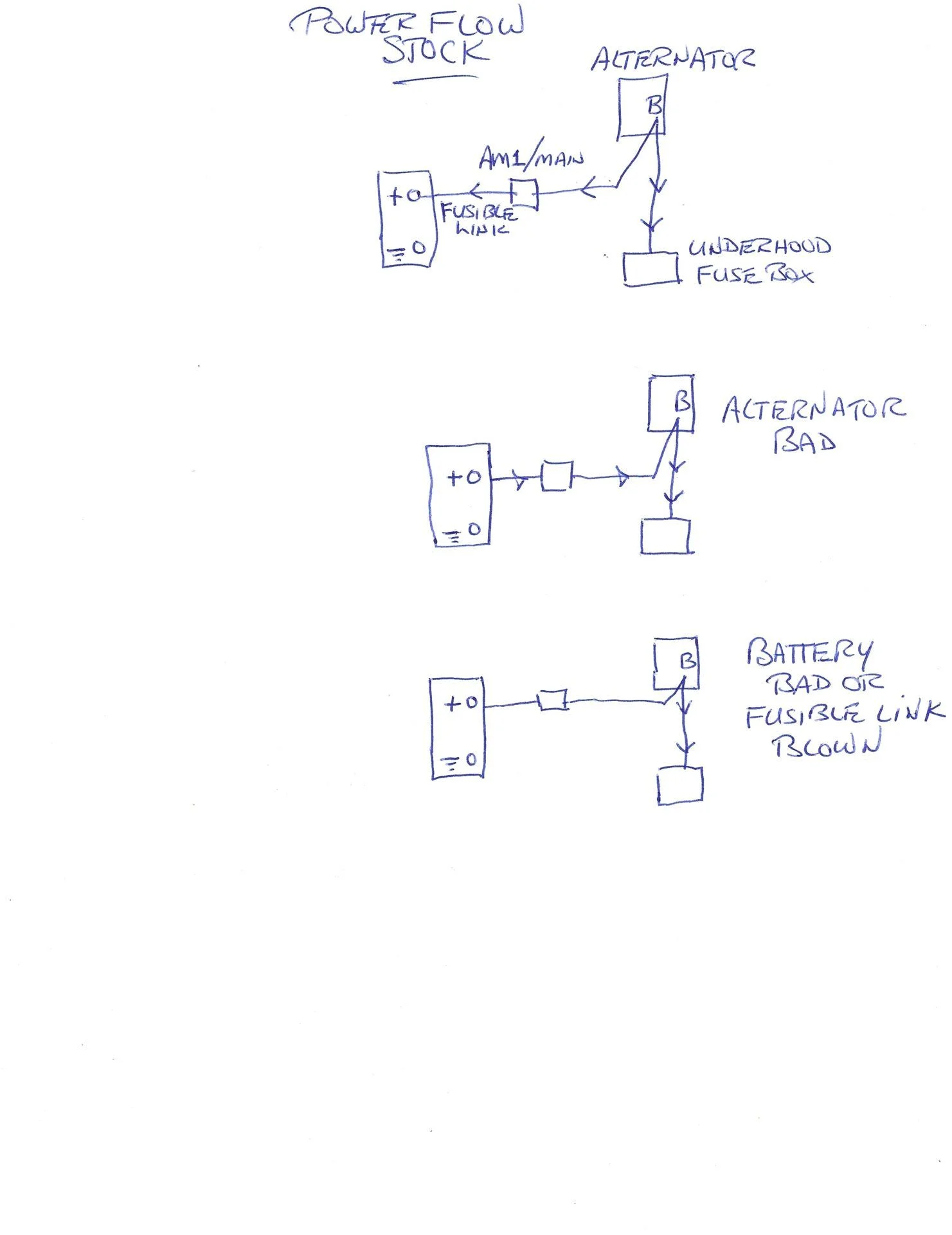
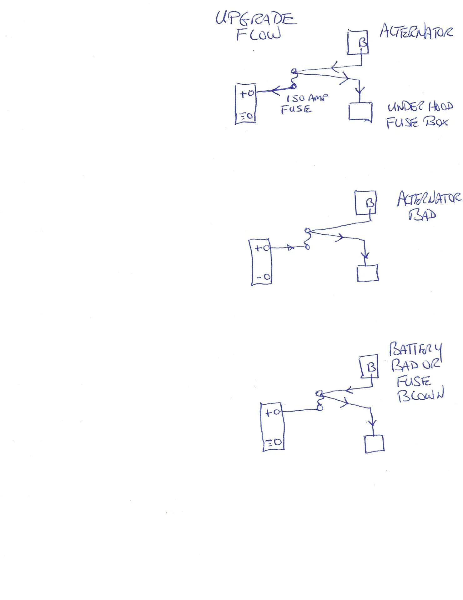
There are two wires crimped in the stock "B" post ring connector that attaches to the alternator. One is the charging wire that goes to battery positive through the stock fusible link. The other wire goes from the alternator "B" post to the under hood fuse box. This supplies some critical circuits so if the fusible link blew these circuits could be supplied by the alternator. Likewise, if the alternator went and the fusible link was good these circuits could be supplied by the battery. With the upgrade alternator the fusible link is being replaced by something like a 150 amp fuse so by doing it the way described above power is still being supplied to the under hood fuse box the same as stock.
Hopefully, here are a couple of crude drawings to attempt to illustrate what I was saying. As can be seen in battery bad or fuse blown drawing, it is important to put the stock wire back on the correct side of the new fuse. If it was on the other side of the fuse block and the fuse blew, then no power would go to the under hood fuse box. Just guessing from memory I think this wire to the under hood fuse box feeds the ECU, brake lights, hazards, head lights etc.