A few pages back someone asked if eliminating the air induction pump would make it difficult to pass SMOG in CA. Any thoughts on that? Has anyone done this in CA and still passed SMOG? thanks...
Navigation
Install the app
How to install the app on iOS
Follow along with the video below to see how to install our site as a web app on your home screen.
Note: This feature may not be available in some browsers.
More options
Style variation
You are using an out of date browser. It may not display this or other websites correctly.
You should upgrade or use an alternative browser.
You should upgrade or use an alternative browser.
06/07 Air Induction Pump Failure & Bypass (8 Viewers)
- Thread starter TexasCrane
- Start date
This site may earn a commission from merchant affiliate
links, including eBay, Amazon, Skimlinks, and others.
More options
Who Replied?hewitttech
SAIS Bypass Kit
We sell plenty of them to CA. As long as you are able to clear out your trouble codes and go through enough drive cycles to set all the other emissions monitors it isn't a problem. Because it is a secondary emissions system the only thing required right now for this system to pass is that its monitor shows as ready which it will, it will just never run again.
I know you asked about eliminating so I would just like to clarify. Our current V3 and V5 bypass kits can only prevent the system from running.
With the current kits all the electrical components must still be connected or at least something like our pump pack must be connected so it thinks those things are ok and still connected. We just came out with a harness to get around 1 bad pressure sensor and recently developed a sensor replacement and a proxy for the air switching valve solenoids that is similar to our pump packs.
We are currently developing a new product that would actually let you eliminate all of the components of the system but until then we can only prevent the system from running and get around some of the other circuit codes with kit addons.
We sell plenty of them to CA. As long as you are able to clear out your trouble codes and go through enough drive cycles to set all the other emissions monitors it isn't a problem. Because it is a secondary emissions system the only thing required right now for this system to pass is that its monitor shows as ready which it will, it will just never run again.
I know you asked about eliminating so I would just like to clarify. Our current V3 and V5 bypass kits can only prevent the system from running.
With the current kits all the electrical components must still be connected or at least something like our pump pack must be connected so it thinks those things are ok and still connected. We just came out with a harness to get around 1 bad pressure sensor and recently developed a sensor replacement and a proxy for the air switching valve solenoids that is similar to our pump packs.
We are currently developing a new product that would actually let you eliminate all of the components of the system but until then we can only prevent the system from running and get around some of the other circuit codes with kit addons.
When do you feel the new product will be available?
We are currently developing a new product that would actually let you eliminate all of the components of the system but until then we can only prevent the system from running and get around some of the other circuit codes with kit addons.
This is what I want.
This is what I want.
hewitttech
SAIS Bypass Kit
Its been hard for me to dedicate enough time to development and still keep up with other things around here.
Hopefully in the next couple of months. Keep checking our website or better yet like us on facebook, google+ and youtube.
We post all our new products in those places. Although our videos have fallen a little behind also because of time to make them.
Hewitt Technologies Inc.
https://plus.google.com/u/0/b/11528...ts/p/pub?_ga=1.225562335.470974736.1472486661
Hewitt-Tech
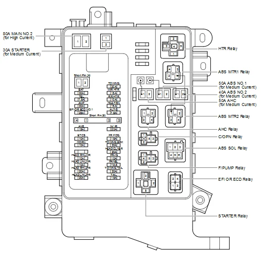
My 06 100 threw the P1442 code a few months ago, at ~170k miles, but didn't experience the limp mode. I am proceeding with the bypass install today, but am having trouble determining which terminal to attach the relay wire to as my relay doesn't have the copper terminals that the instructions say to stay away from (as those are the solenoid terminals). Anyone have any advice on which terminal to secure the wire to? I don't want to blow the solenoids or the bypass, which the Hewitt instructions said are likely to happen if the wire is improperly attached. Thx in advance!

This is my '06. Attach here and you will be good to go.
View attachment 1419352
Excellent, that's great thanks!
Did you install the block off plates? I got the screws loose but have had a heck of a time getting the unit to separate so I can slide the block off plates in.
Yes, I did. I don't recall having any problems separating to slide the plates in. I do remember I had the area fairly well covered with PB. Don't know if that helped or not. If you had no problems breaking the nuts I'd think you shouldn't have too much trouble. Especially with a Texas truck.Did you install the block off plates? I got the screws loose but have had a heck of a time getting the unit to separate so I can slide the block off plates in.
I installed the Hewitt PnP unit back in '15. I can't remember the code but mine didn't go into limp mode either. I recall reading limp mode depends on specifics of what is stuck. I had about the same miles as you when it happened. After installing it has been perfect so I'm sure you will be more than happy.
There is one nut that hasn't been cooperative, and is on the verge of stripping. I used liquid wrench the first go around, and now have doused in PB. I'll revisit tomorrow after work. Thanks again for the quick replies.
Battleship
GOLD Star
Any chance you could post a photo of the two places the plates go?There is one nut that hasn't been cooperative, and is on the verge of stripping. I used liquid wrench the first go around, and now have doused in PB. I'll revisit tomorrow after work. Thanks again for the quick replies.
hewitttech
SAIS Bypass Kit
Hey Chris, Sorry I didn't get back to you over the weekend about the relay. That is the correct one that westtx28 posted.

on top of engine?? I thought they went on bottom side in fender well, behind skirt... please advise or post a proper install video?
hewitttech
SAIS Bypass Kit
Sorry, that pic was a for a 4.6L, time changed and no coffee this morning... I deleted the post.on top of engine?? I thought they went on bottom side in fender well, behind skirt... please advise or post a proper install video?
Correct on the 4.7L the plates are easiest to install at the air tube flange at the bottom back corners of the cylinder heads.Easiest way to get them in is to go through the fender well and back the stud nuts all the way off.Then have someone go up top with a pry tool and a block off wood against the back of the cylinder head and air tube across the back of the engine near the flange and pry just enough so you can slip the plates in.
On the 5.7L the plates install at the same location but the trick is to us a floor jack with a stick of wood from the jack through the trans tunnel positioned on the tube across the back of the engine right behind the flange. Just a couple bumps of the jack will open that up enough.
The 4.0L and 4.6L the valves are on top of the engine and are easier to install. On those the tube and valves can be unbolted from the top of the valve cover, the plates slipped in and then everything put back together.
Driver Side Plate Location 4.7L engine
Come at them however you can ") . You may have to come from bottom, side and top! Here is a picture of your target, one on each side.
. You may have to come from bottom, side and top! Here is a picture of your target, one on each side.

. You may have to come from bottom, side and top! Here is a picture of your target, one on each side.Ok so the top nut in the picture above is officially stripped. Anyone know what size the actual that flange nut is? I need to get a replacement. Nut splitter is already en route via Amazon.
Paul - thx for you email follow up earlier on the topic. Agreed - definitely do not want to break a stud!
Paul - thx for you email follow up earlier on the topic. Agreed - definitely do not want to break a stud!
hewitttech
SAIS Bypass Kit
10mm head and pretty sure it is a 6mm thread diameter. You could also try a NEW set of brand name vice grips on that nut, they have a hex key tightener on the adjustment. Bastard of a location to drill out a stud out. Other option, heat the flange the stud is in with a torch and remove the stud with an internal torx socket.
On the 4.7L our plates will also fit the other end of the tube at the No.2 ASV at the back of the engine. Usually in better shape but harder to get to. Long extensions.
On the 4.7L our plates will also fit the other end of the tube at the No.2 ASV at the back of the engine. Usually in better shape but harder to get to. Long extensions.
Great thanks. Good call on the vice grips - will check out be new ones as you suggest.
on top of engine?? I thought they went on bottom side in fender well, behind skirt... please advise or post a proper install video?
Here is another link with a few good photos:
2005+ Emission/Air Pump Failure?
Thanks!!