Look what I found.... 1961 FJ40 FST

This site may earn a commission from merchant affiliate
links, including eBay, Amazon, Skimlinks, and others.

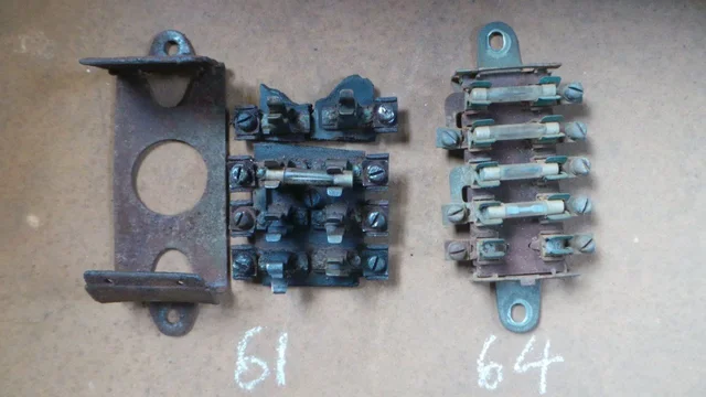
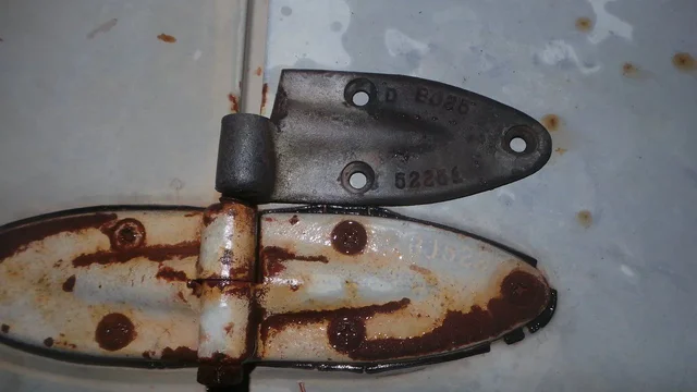
rusty61 hinge pictured loose next to a 64. no sure how visible the numbers are in this pic but it might give you the idea. dont mind the visible bolt head; a po mod i imagine. most my stuff has this mod in one form or other and is this that led me to assume one hinge half is threaded. i just hadnt ever really studyed this stuff before.

20150305_233328.webp

believe this to be the correct oem look regards hinge pin.

20150305_232915.webp
 
i do know the pin stays solid on one side, because i remember sliding the hood sideways to seperate the hinges on an old 40
 
wondering if the pin is 'stepped' or the holes slightly larger on one side to allow for movement? reckon i can drill these out but havnt got to it yet. its been all about wiring. got fusebox seperated; tho complete PITA!

20150307_153809.webp

some 'mess' to deal with.

20150307_153506.webp 20150307_153516.webp 20150307_153529.webp
 
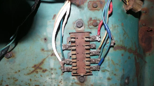
donor 64 fusebox fitted. had to join it where top light circuit had been cut to bypass the fusebox. also tape up a little sun damaged wiring and etc.

20150307_221117.webp

not very pretty but do the job. trying to save all the original harness and just tidy up where i can without doing any further damage. feel im making progress; and learning a lot as i go which is fun. small steps.

20150307_221302.webp 20150307_221033.webp
 
and look what recently turned up (among other treasure) from mudder cult45! very timely! thanks cult; i owe you some emu bitter!

20150305_165815.webp
 
Mine were sheared off at the center so I redrilled and used a 5/16 stainless pin. I'm guessing one side was pressed or knurled.
IMG_1042.webp
IMG_1043.webp
 
and look what recently turned up (among other treasure) from mudder cult45! very timely! thanks cult; i owe you some emu bitter!View attachment 1041601

Good to see this thread hasn't stalled through want of light switches ;)

It needed to go to a good home. And it has.
 
thanks all

cruisernerd - nice work. will try and drill mine out

mr hdjtachtig - that would be great. would love a pic of how your light switch was wired up; i think mine has been messed with. i also have 2 mystery wires that exit the harness near the 2 that go to the traficator (turn signal) relay. will get some pics tonight of the couple questions i have.

cult - its much prettier than the piece of fence wire jammed into a seized solid switch i had. i needed heat to even get it out of the dash. basically i need heat for everything i touch on rusty!

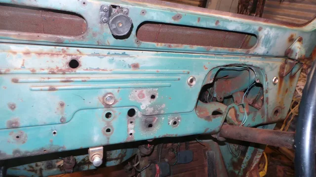
much of the under dash mess on rusty is a po hack install of trafficator. they also swapped out the original indicator assembly unit (the one that clamps to the lower steering column) for another non landcruiser english unit. "...lucas...prince of darkness..." i hear my vintage auto spark mate say!
 
Hahaha Lucas is the anti-ND?
 
dunno what ND is cult.

anyways tinker tinker under the dash. got the handbrake assembly out. was very seized at the top pivot (marked). complete PITA because the right mount bolt was hidden. couldnt really heat this pin under there with the wiring. heated the mount bolt from the firewall side. a win anyways

20150308_225523.webp 20150308_225614.webp
 
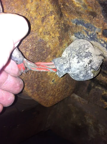
mr hdjtachtig - these are my mystery wires. thinking perhaps they used to go to the 4wd warning light? above the FD knob?

20150308_194547.webp 20150308_194618.webp

and the light switch...

original 61 as i found it

20150308_194436.webp

and donor 64 courtesy of cult

20150308_194504.webp
 
Nippon Denso!
 
Here you go Henry:
Lightswitch connections; The connections are named H, L, BAT, M, P. Clockwise:
H Red/Grey
L Green
BAT Red
M Red/black + red for the so called darth vader interior light
P Green/black

Foto 09-03-15 17 18 47.webp
Foto 09-03-15 17 21 31.webp


Mistery wires:
Blinker relay Connections: L, B, Ground. (Dont know if this is stock, seems a bit too shiny to be 53 years old)
L Green/Blue
B Green/Brown
Ground white Black, under one of the mounting screws of the blinker relay

Foto 09-03-15 17 14 21.webp


4WD light
both wires green/Yellow
Foto 09-03-15 17 15 46.webp

After 20+ attempts most pics are orientated as I want, but this last one keeps getting upside down aaarghh.
 
thanks heaps for that mr hdjtachtig. my mystery wires seem to be the 4wd light.

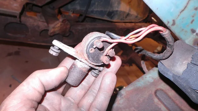
dimmer switch is a corroded lump now pulled from the floor and hanging from its wires waiting to be swapped for a better unit. hopefully will get a chance for a tinker tonight. no doubt will be back with a heap more questions! girl is printing and laminating the wiring diagram you posted at her work today.

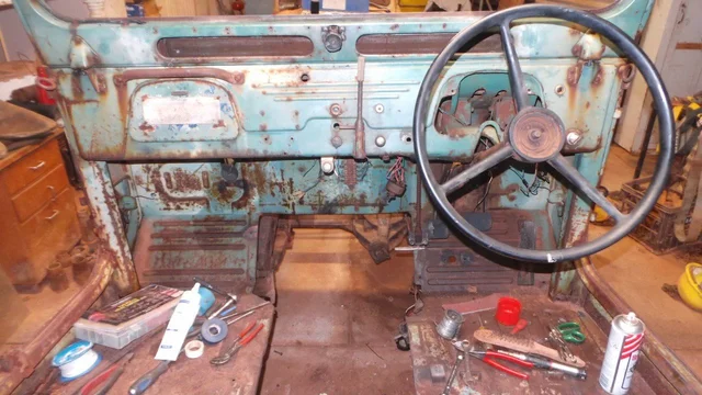
at present just going right through the firewall and undoing every stud and bolt, applying anti seize and reinstalling. things like the throttle linkages, vacuum line mounts, horn relay mounts etc etc. most things need heat to dismantle. cleaning all electrical joins and earths etc. want to have all this under dash sorted before i reinstall motor and box.

also sourced the correct thread tap set and sorted a few more broken studs; including tub bonnet hinge i broke couple months ago. i currently have no broken studs of my own making in rusty. im a bit proud of that.
 
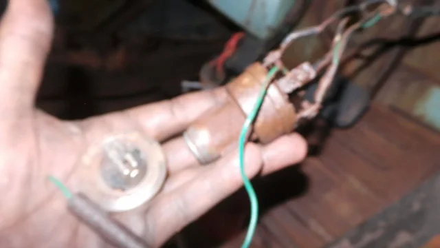
got all the firewall bolts sorted. made a little start loosening up the original vacuum line wire hose clamps etc. handbrake cleaned lubed and ready for reinstall. got everything i can out of the dash. most bits needed heat which blistered the paint a bit but gave that a rub with some emery and it will blend in in time. cant budge the dash indicator light mounts but got the globes out so they will be fine. cant budge 4wd light without risking damage so soak more and ignore for now. still working on darth vader light (remnants) pull.

slowly finding my way through the wiring and coming up with a plan;

fusebox swapped out for a 64 donor.
lightswitch to be swapped courtesy cult45.
dimmer switch to be swapped.
trouble light plug to be swapped.
wiper switch i think serviceable.
everything trafficator and indicators to be swapped.
everything horn to be swapped.
brake switch to be fitted.
wrong ignition switch to stay for now. i dont have a donor with key, this one works and is 'period correct'!

charge circuit will be alternator fit after motor reinstall.

much of this wiring is not necessary for what i am building. rusty really needs no more than a charging alternator and a headlight but i am enjoying the challenge while learning a lot about this old wiring. good practice.

immediate plan is;

lights - power to terminal blocks.
wipers - power through switch. will leave this disconnected exiting switch the remainder of this wiring sun perished and unservicable.
horns - power to horns for now. may tinker inside these old horns later.
brake and tail lights - there is no (and prob never likely to be) any wiring running to rear of this tub. be nice to get power to the rear exit plug on the firewall.
darth vader and trouble light plug - to work.

havnt looked at the dash much. vague plan is to build one from the 2 using the orig 61 wiring and old style warning lights. these warning lights seem simple to resurrect.

so... work in progress. nearly ready to throw a battery at this.
20150310_230828.webp 20150310_232610.webp

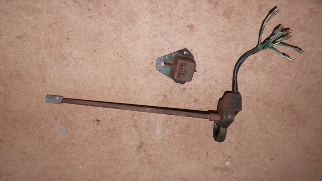
pics - donor indicator unit next to the po 'lucas' install. refurbed handbrake. i am also trying to pull the pedals for a clean and lube. they are not seized, but very stiff. got the bolts loose but having trouble getting them out.
 
(the bolts that is)

finally a question. how does this pin on the 4wd lever come out. havnt tried yet and dont really need to remove it; it just interests me. there doesnt seem to be anything obvious holding this in. press fit best left alone?

20150310_231306.webp
 

Users who are viewing this thread

Back
Top Bottom