How to LS Swap a FJ60 or FJ62. Quick and dirty guide for regular folks wanting to do an engine swap in their driveway. (14 Viewers)

This site may earn a commission from merchant affiliate
links, including eBay, Amazon, Skimlinks, and others.


Part # 917340

This is what I got. It is a double pass and the single is like $179 or there abouts. At the bottom has the links to the shroud kits. Keep in mind this does not have a trans cooler. I prefer an external anyway. My transmission has been very happy with that setup. Honestly I think the internal inside a radiator actually warms the trans up more than it needs to go.

I got the 26 inch radiator and I was able to fill in the whole space with the core. The 60 might even be able to fit a bigger radiator, not too familiar with them.
View attachment 2871376

If I had means to TIG or the time to TIG I would maybe suggest that for better looks, but this setup is working really well.
View attachment 2871375


This is with condenser and trans cooler.
View attachment 2871377
Sweet Piggy! Are you planning on getting new License Plates of the Covid variants?
 
Sweet Piggy! Are you planning on getting new License Plates of the Covid variants?
Oinkmicron? I have been thinking about changing the plates. But probably staying away from infectious disease references. The whole swine flu and FJ55 Pig thing is cool but only a very small group of people understand the reference.
 
HVAC and AC.

This is one step that really adds quite a bit of expense to the swap. This first part is just replacing all of your AC Components with new parts. It is not completely necessary to do, so if your old parts are still okay, give them a clean and re use them. Reusing old good parts will save you a chunk of money. Get a new dryer though. Theyre cheap. I am unsure if evacuating your old AC components removes the old oil from the system or not. Maybe someone can chime in on that. I used all brand new parts so had to add PAG46 oil to dry parts.

Denso AC Condenser - 8057-05239744
Denso Evaporator - W0133-1748697
Toyota AC Expansion Valve - 88515-87004
Toyota Pressure Switch - 88645-30250
Four Seasons 33403 Filter Drier
@ChaserFJ60 Receiver Dryer Spacer Link

You are going to want to use R134a and not R12 for your AC. The replacement Denso dryer is set up for R12. The R134a dryers that work for the system are smaller in diameter than your dryer holder so thats what the spacer is for. Dont remove the ports on the dryer until you are about to connect your AC lines to them.


Whether or not you are going to change your Evaporator or not, youll need to remove it. You can do this with only removing your glove box. Heres a good thread on it:


Once removed, mark all of the electrical connectors in there so you remember to connect all of them. Its easy to forget one and youll spend an hour wondering why your compressor isnt kicking on with the dash button being pressed.

Once the lower evaporator is removed you can either replace it with the new parts or clean out all the dirt and leaves from it. Before putting it back in add 2 oz of PAG46 oil with dye to one ports and blow it into the evaporator.


(not recommended) Then youll remove a resistor from the Amplifier shown in this link here:


*************************

(recommended) You can also bypass the Toyota Amplifier completely and wire the AC to work to mirror the GM system, but its a little bit more work involved and using the toyota stuff is much easier. And much less work. Controlling the AC with the ECM or PCM is a much bettter move than using the 35 year old board that is the amplifier, and it will be all self contained. Later on in the thread I’ll show you how to bypass the Toyota ac system to work with the GM pcm to control ac idle up and e fans, if you are using a Gen 3 pcm.

Its here in post #79

Get your Evaporator reassembled and reinstalled into your dash and make sure to reconnect the plugs.

If you are wanting to replace your heater core this is a pretty great time to do it. I didnt and just flushed mine and havent had any issues.


Your Condenser should already be reinstalled, so youll need to relocate your dryer bracket somewhere. I mounted it next to the radiator on the support, you can really put this anywhere. Just make sure the hoses have a clear path.

Remove your GM Compressor and remove the drain screw and try and remove as much oil as humanly possible from it so you can start from scratch on the oil amounts. You basically turn it upside down and spin the belt pulley until it all drips out. Once its pretty empty youll need to fill it back up. I ended up putting about 3 OZ of PAG46 with dye back into it before reinstalling it with the ports plugged off. This is for the Denso 10S17F compressor that came with my motor. If your donor truck had rear AC you will have a larger compressor that is a little bit different. The 10S17F is the most common compressor out there for these motors though

The hoses are where youll run into some problems. You can do one of two things. Rebuild the ends of your Toyota hoses, or Use adapters. I used a guy locally here in Memphis named Metal Mike at Automotive AC Hose repair. He basically will take your Old lower evaporator hose that goes from the Evaporator to the GM compressor, and the Compressor to the Condenser and braze on GM compressor fittings onto one end of them. That way its toyota on one end and GM on the other. You will reuse your upper Evaporator hose and your hose from condenser to dryer without modification. Im sure you can reach out to him and see if he can do the same for you, but most automotive hose places or hydraulic line shops can do this. Whoever does this will need your two toyota hoses to modify them. You will need to have the exact measurements of hose lengths you need for them to build the hoses for you. You can also go to the salvage yard and pull AC lines from a GM vehicle that match up with your AC compressor for like next to nothing. This way it will be OEM GM end fittings. Doing it this way will allow you to bolt the hoses directly to the AC Compressor instead of using aluminum adapter fittings on the compressor housing. If you look at the photos of my hoses below, the metal part of the lines with the elbows were made by Mike. The GM side was braised onto a hose end fitting he had, and he added the high and low pressure ports to them. He then crimped them onto new rubber hose with a hydraulic crimper. Its worth giving this dude a call. He does incredible work for literally everyone in the Memphis area, and people even resell his hoses on the internet. That being said, if you have an automotive hose or hydraulic hose shop locally to you, they can totally do this for you.

The other option is to use adapter fittings on your Compressor. I believe you will still need to have your hoses rebuilt to match these adapters so might as well just use the GM ends.


**** Very important, if you are planning on running a gen3 motor, and you are planning to run your AC through your PCM so you can have Idle speed increased when the compressor is on and have the computer control your fans to come on when you turn the compressor on, you will also need a pressure sensor port welded/braised or crimped onto your high pressure line somewhere.

Links:
-weld on
-Crimp on
-For more information on the High pressure ports and sensors and wiring the AC system up, please read this thread in this link here

ZkTasEXh.jpg


You will need to Fill your components with PAG46 with dye refrigerant oil for R134A. The silverado and tahoe have an 8 oz capacity of PAG46 and the FJ60/62 has a 5.2-6.2 capacity for the R134a swap. I ended up using 7oz of total oil for the system. The GM Denso compressor looks to be bigger than the Toyota Denso one so im assuming the oil quantity difference is there. I put 3 oz into the compressor and 2 oz into the condenser and 2 oz into the evaporator.

Once your lines are built you can connect everything up. Try to minimize the time that the dryer is exposed to open atmosphere and connect the lines quickly. It is pretty obvious where the lines want to route through the core support and depending on where you mounted your drier the rest will probably run along the passenger fender.

Until your motor is able to crank and run, you are done with the AC lines for now. All that will be left is filling it with R134a refrigerant. Since you used PAG46 with dye, you can run straight refrigerant without oil or dye. It is cheaper. I used 3 or so cans of Chemours R134A-12v from oreilly. Its like $10 a can
 
Last edited:
So theres about 50 different ways you can go with the shifters on the LS Swaps. For the Transmission, most people choose to go with the Lokar Shifter that looks like a manual shifter. I went this route as there wasnt many other options that looked good. B&M has a shifter as well, but it looks more 70s muscle car. Another option would be to use a FJ62 automatic Trans shifter. This is the route I wanted to go with but I couldnt find one in good condition. You could wipe off the paint on the lights on it and get Mo Faraz to make you some Dry transfer decals for them and wire them into a AT Temp light or whatever you wanted them to be. These are kind of hard to find in super good condition so I just ended up using the Lokar Cable Shifter. One of the coolest shifters ive seen was my buddy adapted a Tacoma column shifter to his steering column and used a column shift kit from lokar for the 4l60e in his LS Swap in his firstgen 4runner. This freed up his floorboard completely down there for a storage area with BMW cupholders that he 3dprinted. The sky is really the limit with this stuff.


If you go with Lokar, make sure you get the cable operated one. The Linkage one will rattle like crazy. If you have ever adjusted or installed a shifter on a bike, you are already overqualified to install the cable shifter. Theres no cable tension adjustments or barrel adjusters. Just follow the instructions and its simple to install. The cable ones go out of stock quicker for this reason. I originally had a black 12 inch shifter with a black shift knob PN: CO4L60ECXMB ordered through motorstate but it was backordered so long that I ended up just buying a 16 inch Silver shifter that was in stock and painting the lever arm black and put a black shift knob onto it. The 16 inch length Cable shifter puts the shifter right at the same height my h55f shifter was at. I was hoping to get it a little lower and out of my dash but due to covid i had to make due. The good thing is all of the parts for these shifters are available for order so if you dont like the length you have, you can order a different length or a different shift knob. The mushroom knob, the one that i got, is kind of the most used one out there. I really wanted the Hi-Tech black knob but again, out of stock. Just make sure you order the matching shifter for your transmission and it comes with 90% of what you need to install. The Part numbering system is on page 9 of this pdf to help you figure out which shifter you want to order. Cable operated 16 inch single bend will pretty match up to stock, the rest is just what color and knob you want. Basically, CO4L60ECXMB means Cable Operated 4L60E C(12inch single bend) X(black shifter lever) M(mushroom shift knob) B (Black Shift Knob)


You can aim where you mount the shifter so it doesnt interfere with your cig lighter and get it as forward in park as you want it to be.

As for mounting the assembled shifter to the floorboard you can kind of get creative here. I Traced out a plate of steel and covered as much of the hole in my floorboard as i possibly could. I then traced out where the shifter would go on that template and drilled holes and welded nuts to the plate to hold the shifter to that plate, finally i cut a hole for the shifter arm to pass through. They make specific weld nuts for this. Theyre not needed but they work a LOT better. Make this hole as small as you can possibly get it and have no interference with the shifter arm, this will keep road noise and heat out of the cabin of your truck! To fasten the plate to the floorboard i just shared the holes for the shifter boot. Be sure to check the throw of the shifter arm. I didnt the first go round and had to trim some of my floorboard and also trim the shift selector arm a little bit. Underneath the plate use some rubber mastic tape as a gasket to get a perfect rattle free seal between this plate and your floorboard. Disregard the sharpie lines on the plate, i was originally planning on making the plate sit down in the hole but gave up on it.

Voltage a little high on the nut tacks hah

AvDYJUtl.jpg

TC3Jr6Ol.jpg


Had the shifter a little too far left to share that bottom left hole with the shift boot, had to trim the corner out of it. Having it this far left also made the shifter interfere with my shifter boot. I would recommend not trying to share that bolt hole with your shifter if you can and getting it a little bit more forward than this.

jPtJK1kl.jpg


TGnba3ml.jpg


You will have to drill 2 holes under the front of your center console floorboard area to hold the cable holder, if you have nice carpet youll need to remove the carpet. If you are planning on replacing your gross carpet, send it.

The shifter placement you can get a little creative with. Just kind of move it around and see where you want it to live, theres no real RIGHT way to do this. I kind of rushed this, when i replace my carpet i am going to go back and stiffen up the plate i made a little bit. It flexes ever so slightly since its sheet metal. A few thicker support straps in there and it will be rock solid.


The transfer case shifter is pretty simple with the 4l60e. With the 4l80 and 6l80 you will need to make some kind of bracket to hold the shifter pivot to the side of the transmission. For the 4l60e, make sure you have mounted the t case shifter bracket to the side of the t case adapter like explained in the bottom of this post.

If the mounting bracket is modified like in the post, you can just use your stock transfer case shifter. You will set it up pretty much the same way, however you will need to add length to the Shifter arm. Theres no real science to this, just kinda get someone to hold the shifter lever from the top where you want it to sit and measure how much length you need to add to the shifter and get some Steel rod from the hardware store and weld it together. This part is pretty simple.

85Fyxsdl.jpg


If you notice on the left side where the extension rod is connected, I have it offset to the left a good bit from the old shifter. This moved the entire shifter over left and closer to me in the driver seat so i dont have to reach as far to shift into 4wd. The weld is fat as s*** there because the root pass had to be pretty thick to fill the offset pieces. The shifter is plenty strong, i tossed it off of my roof into the street and there was no damage. This is also a good time to add an extension to the shifter to make it longer and easier to reach Like this one here. Just be sure the shifter doesnt hit the walls of your floorboard at any time in operation, and give it a little extra room to account for your driveline moving so it doesnt pop out of gear.


Another option is to use a twin stick. This is a less stock looking option but it will operate much better. The design is much better as well. In hindsight, probably should have just done this.

p1020021-jpg.891709


Here is the finished product of the Lokar 16 inch cable shifter installed onto the floorboard and my modified T case shift lever. You can see that the tcase lever offset to the left some to make it easier to reach


RFdJFt5l.jpg


Also, dont worry about wiring anything to the shifter if you are using an automatic transmission. All of the neutral safety stuff, reverse lights, etc are contained in the transmission and its harness, NOT the shifter. The only reason you would use some of the wiring on the shifter is if you were trying to add a PRNDL but even those kits use their own wiring to your transmission.
 
Last edited:
I like the look of that shifter better. I used a B&M ratchet shifter, because that is what I already had.
 
I like the look of that shifter better. I used a B&M ratchet shifter, because that is what I already had.
Hey man if it works it works! The Lokar shifter wasnt my first choice either, but was kind of the easiest one to install from what i could find.
 
Wiring stuff Part 1. Ideas, thoughts, and tools you will need.


So before you get started with wiring youll want to unplug the stock wiring harness from your headlights, turn signals, and everything that is connecting it to the engine bay. Then just pull it all the way out so its just kind of dangling there. Youll pretty much only be reusing your oil pressure wire, water temp wire, headlights, turn signals, corner marker light wires, horn wires, etc. All of the VSV wiring and the emissions stuff can be removed.

You want to unloom both the driver and passenger side Toyota harness completely and remove anything you will not be using. Use the marine heat shirink to terminate the wires.

w44iQe6l.jpg


You will be relooming these harnesses and run them behind the fenders later.


Now that you have a completely clean engine bay with no GM wiring and no Toyota wiring in there, youll need a standalone harness. Theres a few ways to go about this. You can go with a GM PCM or ECM (gen4) and a standalone harness, or you can go with a stand alone harness like Holley TerminatorX or FiTech if you want to go with their engine control. Those two will need a little bit more research done as i didnt go that route so have no info to give on them, maybe someone can chime in on the pros and cons on those.

Ive got a good relationship with a tuner locally who tunes FormulaD cars so I just went with the stock PCM. A good tuner can remove VATS and put a safe base tune on your PCM before you even start wiring. For this base tune, be sure to tell the tuner your differential gear ratio, your ACTUAL tire diameter... like go out and measure it, and if you are using a red/blue gen 3 pcm or a green/blue pcm with the code (12576106 – 12570558) on it, tell him to switch the AC request signal to ANALOG 12V for your AC Control. This is for Gen 3 pcms only.

This will keep you from having to mail your pcm off to someone to unlock the vats and put a random tune on the PCM. Its really important that after you get your swap entirely done, to go back and get a full tune on the PCM. This will take into account your newly built exhaust, fix the trans shift points, and squeeze out any performance they can get for you. A base mailed in tune will never be able to do this for you. Even if you have a 100% stock LS the tune is worth it. Plus if you installed a cam or intake or anything youll need to retune anyways. A base tune isnt something to just run your truck on forever. Youll be doing yourself a disservice after doing all of this work to not finish off your build.

*Everything from here forward is assuming you are re using your GM PCM/ECM and doing a standalone wiring harness.

Anyways, after you have your PCM/ECM unlocked, youll need to figure out what kind of wiring harness you want to go with. Theres a few different options out there from pure junk to slightly less junky to great. Dont be tempted to buy a harness on ebay and alibaba. That has bad news written all over it. Buy a nice harness. This will save a ton of hassle for you. After looking at a ton of wiring harnesses on the market, there are really only 3 that i would suggest you using. Painless Performance, BP Automotive, or PSI Performance. All three of these use brand new delphi connectors, stock wiring, and stock wiring colors. They are very high quality.

Without a doubt, BP Automotive is the best harness you can buy if you are using the stock PCM. The owner used to work at GM and they literally put everything you need in there. I had to build my own separate AC Pressure sensor harness because painless does not include it in their harness. BP Automotive does. Howell doesnt. PSI doesnt.

If you order from BP Automotive or PSI try and get them to ship the harness unloomed and do the looming yourself. The Painless harness comes unloomed. I am suggesting that you loom up your harness yourself because you will be shortening wire runs, and manipulating the harness to fit your engine bay the way you want it to. If you buy a preloomed harness, you are stuck with what that company decided to use or youll have to unloom it anyways. All 3 of these companies ship very good thorough instructions with the harnesses. If you want an example of bad instructions, look up the instructions for the Howell harness.


Something very important is to keep away from wiring harnesses that dont use enough fuses in the fuse block. Companies like Howell and speartech lump everything onto 4 fuses. Howell for example has your TCC lockup on the same fuse as your fuel injectors. If you have a short on that circuit you not only lose fuel injectors but TC lockup in your trans. Another thing is they ship their harness preloomed. They also do not wire in anything to run your fans and AC off of the GM pcm. Howell also for some reason wants you to use 4 O2 sensors for gen 3 truck motors which is not needed. Lot of weird stuff going on with the howell harness.

Dont buy the howell harness. Its probably one of the worse options available.

Painless, BP automotive, and PSI all have incredible customer support too and will help you along the way, and wont get mad at you for calling them to ask questions about PCM pinouts and what not.

That being said, if you have the extra time to mess with it, you could split out the fuse block on these a little bit more too, painless/bp/psi all have the incjectors and coils on their own fuse, but you could split them out to left and right bank for an even better setup.


Moral of the story here... buy the BP automotive harness. I used painless and if i could go back id just spend a little more and get the BP


Lastly, on the wiring harness. ORDER THE WIRING HARNESS FROM THE SUPPLIER DIRECTLY. This is so so incredibly important. You dont want a middle man with no harness building experience ordering your harness for you because its A. Not their truck so they couldnt care less, and B. they might want to take the harness apart and mess with it before getting it to you. Seriously.... this happened to me. Do not trust anyone besides the harness manufacturer to touch your harness before receiving it. Especially some random Shop middle manning parts. Getting this wiring right is one of the most important parts of your entire swap, and besides the fuel lines one of the ones where mistakes will cause a fire. You dont want to add any unknown variables into this part.


Another option if you have a lot of time is to just take apart the harness that came with your engine. This is the most time consuming option but the cheapest. You have all stock wiring and connectors already in your hands. You can split up the fuse box as much as you want and set it up however you want. LT1swap has a really good guide on how to do this. The built harnesses are SO much easier though, and come with installation instructions that make it a breeze. Seriously, once you have the motor side hooked up, youll only splice into a few wires onto the LandCruiser and youll be in business.


Ok so you ordered a harness (the photos in these posts will be of the Painless Performance harness). Now you will need a few tools before you get started messing with this stuff.

Youll want some good wire strippers, Open Barrel Crimp tool (sometimes called B crimper), Regular crimp tool, Multimeter with autorange and continuity tester, a delphi terminal tool, and a pack of open barrel wire splice connectors. You will also be pretty well off buying some delphi GT150 male and female terminals. Youll want these if you are going to shorten your wire runs. You can get these from Del City.

01khpFBh.jpg

AYpSshsl.jpg

1000-2317-0-03.png


For the open barrel crimp tool, they make ratcheting ones, but these blue point ones have been the best ones ive used so far. You can get them on ebay for like 15-30 or new from the snapon webstore for like 40 bucks. I had a set of some from amazon and they worked okay but these blue point ones make the best crimps ive found.


If you are unfamilliar with how to do B crimps heres a few examples i did today to show you how to make basic connections (i used small wires that i had laying around). In the next post ill link a few videos as well:

Basic wire butt connection:

rD4HUzXh.jpg

xU6UaNDh.jpg


Splicing one wire in line with another wire:

D3YmiOHl.jpg

ynJfGeSl.jpg

foftbhQl.jpg

qgrjx9gl.jpg


This is how a delphi terminal is crimped on. This is how ALL of your pins in your electrical connectors will be crimped.

fZyKlcwl.jpg


You will want to make as many permanent connections with these open barrel connectors as you can. Avoid using the plastic covered butt connectors from autozone as those are not permanent. These open barrel connectors are what toyota used in your original harness to join wires. Especially hot wires like the Black with yellow stripe wires. These connections are very strong and, opposed to soldering, will not corrode. You dont really want to do any soldering on any of this stuff.

Also remember that after making any connection to use MARINE HEAT SHRINK. You want to use marine heat shrink because it has this glue inside of it and will keep moisture out. You can get this heat shrink at harbor freight, its not any more expensive. Dont use electrical tape, use the marine heat shrink and a heat gun.

You will also be using marine heat shrink to terminate wires that are not going to be used anymore so they are not just open on the ends. To do this, you will just cut the wire, slide the heat shrink over it and leave some heat shrink over the side and shrink it on once the glue melts squeeze it some and that wire is now safe.


For the areas that you will use electrical tape (for the ends of your wire loom mostly) Use Black High Temp Tessa Tape. This stuff has a cloth like material in it, will withstand very high temps in the engine bay, and just flat out looks better than normal electrical tape.


I know all of this stuff seems like a lot but its not any more difficult than using the autozone crimps. There are a few places where you will want to use the autozone crimps so you can have quick disconnects. Where you are using these please be sure to use fully insulated nylon quick disconnect molex style terminals so you dont have any shorts anywhere. Another good trick is that if you are planning on using a ring terminal, you can heat the colored plastic part and push the metal terminal out of it and crimp that to your wire and use the marine heat shrink on it to insulate it instead of that large nylon piece. This is much better looking imo.


This first post is really important before you start messing with this stuff because the harness is really really really easy to mess up. One mistake will have you searching for hours trying to pinpoint the problem, or could potentially start a fire. This might just be my OCD talking, but taking some extra time to do stuff like this will keep your wiring safe, give you a crank on the first key turn hopefully, and make your wiring look super good. I used the painless harness on my swap, it started onthe first keyturn with no codes and has been running great since that day.
 
Last edited:
So theres about 50 different ways you can go with the shifters on the LS Swaps. For the Transmission, most people choose to go with the Lokar Shifter that looks like a manual shifter. I went this route as there wasnt many other options that looked good. B&M has a shifter as well, but it looks more 70s muscle car. Another option would be to use a FJ62 automatic Trans shifter. This is the route I wanted to go with but I couldnt find one in good condition. You could wipe off the paint on the lights on it and get Mo Faraz to make you some Dry transfer decals for them and wire them into a AT Temp light or whatever you wanted them to be. These are kind of hard to find in super good condition so I just ended up using the Lokar Cable Shifter. One of the coolest shifters ive seen was my buddy adapted a Tacoma column shifter to his steering column and used a column shift kit from lokar for the 4l60e in his LS Swap in his firstgen 4runner. This freed up his floorboard completely down there for a storage area with BMW cupholders that he 3dprinted. The sky is really the limit with this s***


If you go with Lokar, make sure you get the cable operated one. The Linkage one will rattle like crazy. If you have ever adjusted or installed a shifter on a bike, you are already overqualified to install the cable shifter. Theres no cable tension adjustments or barrel adjusters. Just follow the instructions and its simple to install. The cable ones go out of stock quicker for this reason. I originally had a black 12 inch shifter with a black shift knob PN: CO4L60ECXMB ordered through motorstate but it was backordered so long that I ended up just buying a 16 inch Silver shifter that was in stock and painting the lever arm black and put a black shift knob onto it. The 16 inch length Cable shifter puts the shifter right at the same height my h55f shifter was at. I was hoping to get it a little lower and out of my dash but due to covid i had to make due. The good thing is all of the parts for these shifters are available for order so if you dont like the length you have, you can order a different length or a different shift knob. The mushroom knob, the one that i got, is kind of the most used one out there. I really wanted the Hi-Tech black knob but again, out of stock. Just make sure you order the matching shifter for your transmission and it comes with 90% of what you need to install. The Part numbering system is on page 9 of this pdf to help you figure out which shifter you want to order. Cable operated 16 inch single bend will pretty match up to stock, the rest is just what color and knob you want. Basically, CO4L60ECXMB means Cable Operated 4L60E C(12inch single bend) X(black shifter lever) M(mushroom shift knob) B (Black Shift Knob)


You can aim where you mount the shifter so it doesnt interfere with your cig lighter and get it as forward in park as you want it to be. This shifter is nice because my whole life I was told my dad to not leave my hand on the shifter while driving, but since its an auto it kind of doesnt matter.


As for mounting the assembled shifter to the floorboard you can kind of get creative here. I Traced out a plate of steel and covered as much of the hole in my floorboard as i possibly could. I then traced out where the shifter would go on that template and drilled holes and welded nuts to the plate to hold the shifter to that plate, finally i cut a hole for the shifter arm to pass through. They make specific weld nuts for this. Theyre not needed but they work a LOT better. Make this hole as small as you can possibly get it and have no interference with the shifter arm, this will keep road noise and heat out of the cabin of your truck! To fasten the plate to the floorboard i just shared the holes for the shifter boot. Be sure to check the throw of the shifter arm. I didnt the first go round and had to trim some of my floorboard and also trim the shift selector arm a little bit. Underneath the plate use some rubber mastic tape as a gasket to get a perfect rattle free seal between this plate and your floorboard. Disregard the sharpie lines on the plate, i was originally planning on making the plate sit down in the hole but gave up on it.

Voltage a little high on the nut tacks hah

AvDYJUtl.jpg

TC3Jr6Ol.jpg


Had the shifter a little too far left to share that bottom left hole with the shift boot, had to trim the corner out of it. Having it this far left also made the shifter interfere with my shifter boot. I would recommend not trying to share that bolt hole with your shifter if you can and getting it a little bit more forward than this.

jPtJK1kl.jpg


TGnba3ml.jpg


You will have to drill 2 holes under the front of your center console floorboard area to hold the cable holder, if you have nice carpet youll need to remove the carpet. If you are planning on replacing your gross carpet, send it.

The shifter placement you can get a little creative with. Just kind of move it around and see where you want it to live, theres no real RIGHT way to do this. I kind of rushed this, when i replace my carpet i am going to go back and stiffen up the plate i made a little bit. It flexes ever so slightly since its sheet metal. A few thicker support straps in there and it will be rock solid.


The transfer case shifter is pretty simple with the 4l60e. With the 4l80 and 6l80 you will need to make some kind of bracket to hold the shifter pivot to the side of the transmission. For the 4l60e if you use the supplied bracket (without the steel spacers) and cut the top tabs and modify it to sit flat on the mounts, you can just use your stock transfer case shifter. You will set it up pretty much the same way, however you will need to add length to the Shifter arm. Theres no real science to this, just kinda get someone to hold the shifter lever from the top where you want it to sit and measure how much length you need to add to the shifter and get some Steel rod from the hardware store and weld it together. This part is pretty simple.

85Fyxsdl.jpg


If you notice on the left side where the extension rod is connected, I have it offset to the left a good bit from the old shifter. This moved the entire shifter over left and closer to me in the driver seat so i dont have to reach as far to shift into 4wd. The weld is fat as s*** there because the root pass had to be pretty thick to fill the offset pieces. The shifter is plenty strong, i tossed it off of my roof into the street and there was no damage. This is also a good time to add an extension to the shifter to make it longer and easier to reach Like this one here


Another option is to use a twin stick. This is a less stock looking option but it will operate much better. The design is much better as well. In hindsight, probably should have just done this.

p1020021-jpg.891709


Here is the finished product of the Lokar 16 inch cable shifter installed onto the floorboard and my modified T case shift lever. You can see that the tcase lever offset to the left some to make it easier to reach


RFdJFt5l.jpg
What made you choose a floor mounted vs trans mounted shifter?
 
What made you choose a floor mounted vs trans mounted shifter?
I wanted to cover the hole in the floor so it would quiet the cabin down some. Also the Cable shifters are all floor mounted and the linkage ones are mounted to the trans itself. The linkage ones make a bit of noise and are more work to install tbh
 
I’ve used BP Automotive on a couple LS swaps and can vouch for their quality and customer service!
I 100% agree. Id even say those are the best harnesses. Better than the Painless harness i used. They use ultrasonic welding for their wire connections and stuff. Its pretty interesting to see what goes into those harnesses when you look into it!
 
Gas pedal. Adding this here because i forgot to add it earlier and dont want the links out of order. My apoligies, writing all of this from memory.

Technically the gas pedal is part of wiring if you are running a DBW setup. Unfortunately I can not be of help for drive by cable conversions because I only used DBW. I have seen other threads of people using a Lokar Drive by cable setup mated to the factory stuff. Youll need to do some digging there.


Anyways, as far as gas pedals go, Gen3 and Gen4 will be very different. Gen 3 uses a separate Gas pedal computer called a Tac Module, that the gas pedal will be connected to, then the tac module will be connected to the PCM. This is the route i went with since i used a gen 3 motor. This Tac module must match the gas pedal from your donor vehicle, and if you buy your motor from a reputable source, it will be included with your motor.


As for Gen4, this will be much simpler. The Gas pedal plugs directly into the ECM. The popular Gas pedal for Gen4 is the Monte Carlo pedal as the arm is pretty straight. The better option is the Lokar billet DBW pedal. It also has built in hysteresis to eliminate pedal bounce on rough terrain. This would be the move for a gen4 swap. A little pricier though.

Gen3 or Gen 4 pedal, you will need to modify the pedal itself to be able to be installed into the footwell of the 60. For the Gen 4, if you get one that lines up well, you can just make a bracket to mount it to the floorboard and call it good. It is a little more involved with the Gen 3 pedal.


For the Gen 3 pedal, you will need to cut off the pedal arm of the pedal itself because most of the pedals come down, then kick to the passenger side. You need it to come down straight, and slightly to the left.


Thankfully for the Gen3 pedal, the upper bolt hole in the pedal mounting bracket will line up with your upper left bolt hole from your stock pedal. You will need to make a little bracket to mate up the lower right bolt hole and it will bolt right in.


What i did was cut off the lower bracket off the pedal body completely, and then cut off the pedal arm leaving a small 1 inch bit of arm left. Using the lower bracket of the GM pedal, i re used the bolt hole and welded it to the side of the pedal bracket. You can use cardboard to get the bolt pattern spacing you need and make sure it all lines up. The lower bracket needs to be slightly more inset than the upper bracket hole to align the pedal properly. This is a "put it in there and see" deal where youll set it in there, see how it lines up. pull it out. See how it fits, take it out. Modify and try again type deal.

Here is the bracket placed on the side of the pedal body. I grinded the body some so it would be a little inset, but it is not a flat mount like this, i had to bend it some to lower it, if that makes any sense. You dont have to reuse this bracket that you cut off the pedal, you can use a pre fabbed bracket, or make your own. I just used this one for simplicity and time.

xXm96aJl.jpg


In this photo you can see the stock pedal and how it bends to the passenger side. I just cut all of that off.


oPy0ONxl.jpg


Once you have the Mounting brackets made you will want to cut off your Toyota gas pedal arm from the bracket. This will be welded to the small arm of the GM pedal arm.

U7CLAIbl.jpg


8wfvDgDl.jpg


So the thing here is that if you were to mount this up as is, the lower edge of the pedal pad will sit much higher than the upper edge, and no matter the angle you use, the pedal will be too high. Dont make the mistake i did and just weld it on thinking it will be good. Tack it on there and see if the overall height is okay, then youll need to break your tacks and heat the pedal arm up and bend it so the pad of the pedal will hit your foot squarely.


See how the lower pad here is the only thing that would touch your foot, and the upper part of the pad is WAY inset? This was with just welding the Toyota pedal to the GM pedal without any modification.

1TxNB0Ml.jpg


Here are the bends i had to make on my FJ60 pedal arm to make the pad the same angle as the brake pedal pad. I wrapped the pedal pad in aluminum foil and heated the arm in a bench vise with a MAP Torch, once it got super hot i bent it using some pliers. This is also a try it and see thing. I probably took it out, cooled it and put it in there to check, and removed it and heated it and rebent it like 5 times to get it right.

Oe4JthEl.jpg


Also, your gas pedal needs to be a little bit lower than your brake pedal. If you line them up to be even, when you transition your foot from the brake to the gas pedal, the gas pedal will be way too high. For this, youll just tack it in there and feel it for yourself.

Here it is now, after the bends and properly adjusted:

jhveKbtl.jpg


I recommend buying a welding blanket and sticking it in your floorboard and positioning the pedal arm and tacking it with the pedal bracket in the truck. This way you can literally see how it will be.


On the GM pedal, the Cut off portion of the pedal will bottom out on the pedal bracket assembly, this is the absolute bottom bottom out point. On the 60 there is a bolt in the floor that will control the pedal bottom out. You want to adjust this bolt in at first so the bolt doesnt restrict the pedal throw. The alignment of the gas pedal will be based off of this bolt. You want your gas pedal to travel to this bolt in its travel.


Once you have the gas pedal aligned and positioned how you want it, put a few tacks on it and then sit in the truck and pretend you are driving. See how the pedal feels to your foot coming off of the brake pedal and transitioning to the gas pedal while simulating normal driving. If it all feels good, you can then adjust that pedal stop bolt on the floor to hit the bottom of the pedal just at the same time as the GM arm is bottoming out on the bracket. I did mine to where light pressure on the rubber bump stop was jsut before the bottom out of the GM pedal arm and bracket, and then once fully depressed on the rubber, the gm arm would be fully bottomed out on the pedal bracket.


Once you feel like this is all positioned okay, take it out and weld it up. Be careful not to burn through your pedal spring. If you burn through this spring, the pedal will be super light and twitchy. Just be careful and maybe put some welding nozzle gel on the spring to avoid burning through it. I burned through my spring and had to weld it back and wasnt able to quite get it to the original spot. My pedal is very slightly jumpy as the pressure required to depress the pedal is slightly less now. This can be slightly remedied in HP tuners when you tune your gas pedal. Ill probably just end ip going back in there and replacing the pedal spring though as well.


Once this is done, all that will be requred for wiring will be one plug. Easy.


Do some extra side research on this pedal thing though, ive seen some people make some pretty ingenious adjustable pedal arms. I didnt research this at all when i did mine and went in completely blind. This is what i ended up with. Theres 100 different ways you can do this to make it make sense in your head


As far as gas pedal, the gen4 definitely is the easier route.


Lastly, if you are using an automatic transmission, the FJ62 wider automatic brake pedal is a pretty much bolt in swap into a FJ60. Just source it and pull your old pedal and replace. I havent gotten around to doing this yet. If you are LS Swapping a fj62 you are already in business.
 
Last edited:
Next you are going to want to take your new harness you bought (hopefully unloomed) and install it into the engine bay. This sounds like a pain, but you want to install it 100% onto the motor. Figure out all of your wire routing here. Plug in every single plug onto the motor.

Good place to start is figure out where the left bank and right bank wires are. Then figure out where you want your Injector wires to live. I found if you spin the injectors to face the rear of the vehicle, you can tuck the injector wires in pretty neatly, along with the coil wires. Plug in your TB and MAF on the passenger side, and your ect and alt on the other.

Once this is done you can find where the rest of the wiring will split off behind the intake near the firewall. you will have a ton of room back here, even if you spaced your motor as far back as it will go. This big area is a good place for the main junction of your harness to live, as half of your wiring will go down the bellhousing and towards the back.

Run each side of the harness down each side of the bellhousing for your trans wires, o2, etc on the driver side, and your starter wires, o2, crankshaft position sensor wire, starter solenoid, etc down the passenger side. These you obviously wont need to connect just yet. Once all of these wires are ran to where they need to be, you should have a fuse box just dangling around and your PCM/ECM connector just hanging out. This is now the part where you will find a place for these items to live.


You CAN depin the 30 or so wires from the PCM connector and run it through the firewall and run the computer inside the truck, most harnesses allow extra wiring to do so. This is also a giant pain so more power to you if you do this. You could just open up the hole in the firewall to be large enough to run the pcm connectors through it as well. All of these GM vehicles had the computers in the engine bay so they are safe under there. On the 60 theres a few spots right on the firewall near the back of the fenders on both the driver side and passenger side that is free real estate, as well as along the fenders or if you have ditched your wiper washer bottle, that bracket is pretty easy too.

If you are using a Gen3 motor you will also need to keep in mind you will need to mount the Tac module as well. With your harness mounted, you will see where you have wire length to mount your PCM/Tac Module/ and Fuse box. Mount the Tac module after the PCM as it connects to both the gas pedal and the PCM.

This is just what I did, there are surely other ideas out there but just kinda looking at it this is what I came up with. I didnt want to be able to see the big pcm so i tried my best to hide it. If you dont care you can make brackets or mount it elsewhere.

I used 
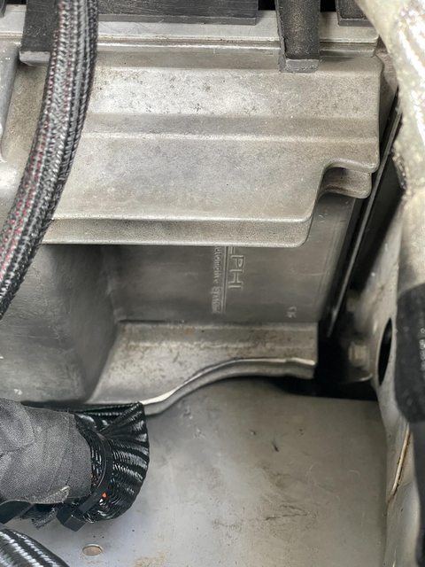
NAL-15995679 from summit, which is a stock plastic PCM bracket. I Cut all of the tabs off of the end of it and found 2 existing holes on my firewall and drilled holes into the center of the bracket and counter sunk them and used countersunk allen bolts to mount it to the firewall. Then i trimmed one of the cooling fins to match the radius of the fender so i could shove it even further down into the bottom of the engine bay. Lastly I bent 2 brake lines to give me better access and mounted the PCM under and to the right of the Brake MC. I used the heat shield that is already there for my harness and ran it inside of it and into the back area of the motor behind the intake. You can also drill holes and use rivnuts to mount this if you want to mount it somewhere else. There are also a ton of other ECM/PCM brackets out there. Both aftermarket and factory from a variety of different vehicles. Find the one that you like the best and will allow you to mount. You want the PCM/ECM to be able to be removed in case you need to change wiring on the connector or if for some reason down the road the pcm needs to be replaced.


Doing it this way hides the PCM pretty well and gives me direct access to the hole that was once my Clutch master, which was used to run the cabin wires through. I still need to clean up the wires better, but this is how it sits now. I am thinking about making a cover plate to block off the entire corner so all of it is hidden.


Note* Mounting the PCM here gives you a lot of extra wire on the thick part of the harness that mounts to the pcm. Im too lazy to depin every wire so i just kind of twisted it and kept the slack. You can also see here that i used the old hood hinge bolts to mount my Tac module to the fender here and spaced it out slightly to allow the Gas strut from the hood to pass behind it. I really really dont like the look of all these wires in this corner. Thats a project for down the road.

yYOuQmOl.jpg


Clearanced fin on PCM to allow deeper depth installation.

TR7nDI7l.jpg


Bent Brake lines and running the harness behind the heat shield for protection. Be careful bending these lines, they are really long and if you break one youre going to have to replace the entire brake line. You can fit a brake line bender in there barely.

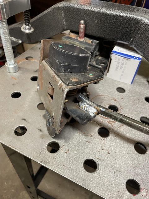
You can also see here that I replaced the bad toyota brake wiring connector with a Delphi GT150 connector. While you are in here, its a great time to replace your old dry rotten connectors with MUCH better delphi connectors. They are safer, and have locks on them, and are also more water and weather resistant. Do this on as many plugs as you can


rc5hSgcl.jpg


Once you have the PCM mounted where you want it mounted, and make sure you can connect the connections to it, then mount your Tac module somewhere. Most of the kits give you a TON of room on these wires so youll want to use the delphi terminals and your open barrel crump to cut these wires, crimp new ends to them and shorten them once you have the positioning of the tac module good.


Lastly youll mount your fuse box. I didnt want to see this thing either but still needed access to it, so i mounted it low on the fender under my air compressor. You really can mount this anywhere you have the wire length to mount it. Just make sure its not too hidden that you cant access the fuses or get a multimeter onto it. For this just drill holes and put some rivnuts into the sheet metal

P7KLs5wl.jpg


This is a part of the swap where you can get creative. Theres no one set way to do it. you can tuck and hide wires, position things so its not in direct eyesight etc. Theres a million ways to mount this stuff. Check out shops and other swaps to see what you like and dont like. Or just wing it like i did. Theres really no wrong way to do it.


Once you have everything mounted where it needs to go, here is where you will take your harness and group stuff together. Use a combination of painters tape and colored zipties to connect wire runs that are travelling to the same area so you can bundle them together, then mark where they split off. This way you can buy less loom and it will look better. Instead of a ton of loomed wires youll have fewer thick ones with smaller branches. For example, you can lump the TB wire and the MAF wire together all the way until they split near the TB, then after that they will get their own loom. You will be looming this on the floor or whatever and not in the truck, so at this point you are trying to get as much info as you can.


Next youll want to mark the wires that are near heat. O2s, starter wires, etc. Anything coming REMOTELY close to your exhaust on either side of the transmission. You are doing this because youll want to buy some insultherm high temp loom for these sections. You can do your entire harness in this stuff but its pretty expensive and its not split so youll have to depin every plug to feed the wires through it. I only did the wires that come close into contact with heat.


Lastly, youll want to start marking wires that are too long on your harness. You want to shorten the wire runs so theres a little bit of slack, but too much slack and wire laying down for no reason looks junky. The reason you 100% connected your harness to where you want it to live is to get the exact lengths of every wire run after you have done your fancy wire routing to hide wires and what not. 90% of the time you are going to be shortening wires, but depending on your routing you might need to lengthen one. Mark all of this stuff now so you can remember to do it on the floor when you are looming it up. You will be using your open barrel crimp tool for this and your delphi GT150 terminal ends. If you want to shortcut it i guess you could cut the wires and then splice the already crimped ends to the shorter wire but with how cheap the delphi terminals are, just do it right and youll never have to touch it again.

When shortening the runs, take a ton of pictures so you remember what color wire goes where in the plug. This will help you a ton.


After all of this is done, you can remove the entire harness from the vehicle and lay it out on your floor. You should have all of your bundled shared runs next to each other and paired off together. Here you will start measuring for what type of loom you are going to need, if your harness didnt come with loom. You will need different sizes so just measure the thickness of the shared runs, and then where they split off for the lengths. After you have your total lengths of loom, add 5 feet to each size just in case for mistakes. Also remember to measure for your Insultherm high temp loom here as well on the pieces you marked that were exposed to heat.


In this photo you can see the grouped wire runs together, the big split on the lower end from the large bundle to the smalller runs on the bottom is the back of the engine by the firewall.

Zb7xu3ah.jpg


Figure out what type of loom you want to buy for the normal pieces, Split woven loom is pretty cheap, you can get it on summit, or amazon or whatever. Its all the same stuff. This stuff is mostly for abrasion resistance and doesnt have a super high heat tolerance so getting expensive loom for your entire harness is a waste. You can just order it off amazon or ebay and be all good for a quarter of the price of the name brand stuff.


For the high temp stuff, youll want name brand loom like insultherm, fire wrap, or volcano. You can order this stuff by the foot online if you look for it. I got a few samples and the insultherm looked the best. It works kind of like a Chinese finger trap, you push it together and its bigger, pull it apart and its smaller in diameter. Measure your wires accordingly.

When you get the loom, youll want to remove the zip ties from your harness that are holding it together and replace with loom, your own zip ties, and Tessa high temp tape as you go. Dont remove all the zipties at once, this will help it stay organized. You can use the tessa tape on the ends and on the unions of wires to seal the loom better and cover the ends. When you are running junctions in the loom always be sure to overlap your loom by a few inches for the best protection then run the tape over the junction. If you just butt them up together it will slide apart or youll have some exposed wires depending on how you twist it.

Also when you are cutting the split woven loom use very sharp scissors, then hit them with a lighter quickly on the ends to melt the frays. If you hold the lighter there too long it will fray even more. Youll get the hang of it really quickly.

Also, pretty important, do one of these at a time, and when you loom the wires, re tape your wire labels that came on the harness very securely, some of these wires will be pushed through the firewall and if you lose a label it will add time to figure out what is what.

Here is my loom partially loomed up and taped. This was still waiting on the Insultherm and to shorten the super long Tac module wires to the left.


H7lRflLh.jpg


Once the harness is completely loomed, you are ready to install it back into the engine bay for the final time. After doing all of this you can see why you want to get an unloomed harness. It is more work, but you are able to tailor your harness to your engine bay much better than if you had bought a preloomed harness and just threw it in.
 
Last edited:
Once your harness is all loomed up you can go ahead and permanently install it into the engine bay.

This post is assuming you bought a quality harness. They will all come with super detailed installation instructions and each of the ends with delphi connectors will have labels on them. Unfortunately its been a few months since ive done this and i wired the entire truck up and cranked it up in one day, so i dont remember every single wire connection that i made but ill do my best to recall what i can. If you have all of the supplies you need on hand, from this point until you hit the first crank, you should be able to knock this out in one day. Perks of getting a good wiring harness. There are also quite a few different options with this like gps speedo and aftermarket tach, etc so ill just kinda be going into what i did, which was kept all the stock stuff.


Most of these stand alone harnesses use the same wire colors and pinouts for everything to mirror the stock GM harness, whatever harness you use, use the manual that comes with it. That being said I used the painless performance Gen3 motor with 4l60/4l80 and drive by wire. Here is the installation instruction PDF to give you an idea of what to expect in this post.


Anyways, Tuck the wires as best you can on either side of the motor for the fuel injectors, ECT, Alt, MAF, etc. Go ahead and install every single delphi connector on your harness that attaches to the motor. You can hold off on the starter and stuff going back down the transmission for now, just let that dangle.

Once everything is connected (dont connect the PCM yet) go inside your truck and remove the driver side kick panel. I went ahead and completely removed the emissions control box and like 10 runs of unused wires. Be sure to double check the Wiring diagram posted in the following post to be sure it is safe to remove the wires. When you terminate a wire use the marine heat shrink on the exposed wire end, heat it to shrink and squeeze the glue for a good bond.

After you remove the emissions control box youll have a nice convenient bracket available and a large empty space against the wall behind it. Youll use this space for 3 relays for cruise control a little later and a dakota digital tach box if youre keeping your stock tach.

Dont be intimidated when youre looking at a view that looks like this...
f4hBqVQl.jpg


Next Youll need to run the cluster of wires through your old clutch master cyl hole and into the cab of the truck. If you angle the Gas pedal plug just right it will fit through the clutch hole. You will need to depin the OBD2 plug to get the wires through though. Just take pics of the back of it and use your handy delphi tool to do it and repin it once the wires are through.

Mount your obd2 plug next to your hood release on the bracket. Then if your harness came with a check engine light you can either just use that one, or piggyback off of the wiring for that light up to your now unused choke light. I just cut and spliced the wires with the open barrel crimps up near the bulb. Terminate the old wires with marine heat shrink. From here you will want to take the strongest rubbing alcohol you can get and rub the words CHOKE off of the choke light housing. Then contact Mo Faraz for a dry transfer decal with the OEM toyota engine graphic and the word CHECK. I measured this with calipers to guarantee that they fit before he designed them.This will now be your check engine light.


x4Q26sal.jpg

KYJ858ll.jpg


From here you will need to make a few various connections. Youll need a right angle drill or impact attachment to open up the hole for your brake pedal switch and install a GM D850A brake pedal switch. When you are done, go back and adjust this switch so the brake lights come on with a little bit of extra brake pedal travel, i mean a little, after it contacts the switch. If you adjust this switch to turn your brakes on with not enough stroke, your cruise control wont work

Install some fully insulated female connectors to the Pink, purple, and light blue wire from your standalone harness and connect them. Light blue will be to your brake lamps. The 4th wire is a 12v + wire. All of this should be in your instructions with your harness.

Youll also make a few other connections that are all in the instructions here are a few off the top of my head:

-fuse block ignition is just switched 12v.

-White Tach wire will either go to your dakota digital box or your tach if you are using aftermarket tach. If you are using the stock tach, youll run the white wire from the standalone harness to the tach input of the dakota box, run a switched 12v to the box, a ground to the box, and a wire from the hi vlt tach output of the box to where the red wire attaches to the back of your tachometer itself. The settings on the dakota box will be 4cyl input, 6 cyl output and high voltage output. I used industrial velcro to mount this box to the free bracket where the emissions control box used to go. It holds up really well just clean the metal really well before sticking the velcro because its bound to be dusty. Dont permanently mount the box yet, youll need to run wires for the cruise relay under the bracket.

-I kept my mechanical speedo so didnt need the vss wire for the speedo so i terminated it just in case i ever change it out.

- AC Request wire will need to be spliced in up by the hvac controls I cant remember which wire I used, i THINK it was yellow, but definitely double check the EWD. You want this to be a 12v + wire.

-Cruise control will be brown gray blue and grey black. These will connect to whatever controls you use. Ill make a separate post on what i did for cruise


Just honestly follow the instructions closely. Thats all I did for this stuff and i had no issues. A few things to note,

-youll need to remove the starter to install the crank position sensor. it also makes it easier to install the starter B+ and Starter Sol wires

-if you used the Marks4wd water temp and oil pressure adapters youll just splice these into your toyota oem harness and theyll send signal to your gauges.

-You need to have good grounds. I did the grounds from the standalone harness to the back of one of the heads, battery to body reusing my old ground strap, then used the other side of it to connect to the frame so youll have frame to body ground. Youll also need to ground the engine to the frame.


My motor came with the Battery + box on the side of the alternator bracket on the driver side. I trimmed the bracket and flush mounted the battery+ box to the alternator bracket and ran and tucked a new loomed + wire up below my TB and to my starting battery on the passenger side. IF you do it right you wont be able to see it. You can do this many different ways.

The tail side of the wiring harness just plugs in. Youll only need to connect the long grey wire for your fuel pump, splice the long green wire from the standalone harness to your backup light (red black i think. Again look this up) wire at the plug on the old toyota harness. This is also a good time to replace these crusty wire connectors with delphi GT150 waterproof connectors. This is also a great time to use some of your woven split loom to cover all of these wires up and make them look nice and tidy.

4x4 light should just be on the transfer case.


For the two Toyota harnesses on either side of the engine bay, remove the wires you are not using and reloom the runs. Im pretty sure i just spliced the toyota ac wire to the gm ac compressor connector. The LC side is a single + wire on the chassis harness, not the engine harness. The LS connector is 2 wire, use the power wire for one of the two wires and the other side goes to ground. I also reused the fusable link wires on the passenger side so it wouldnt disturb the rest of the toyota wiring. Youll keep your side marker, headlights, and turn signal wiring too. Loom all of this stuff up really pretty, then run them behind your fenders never to be seen again. You can pull the AC wire, fusable link and other wires you kept out of the hole halfway down the fender and run it down to the compressor so you have half of the wiring hidden. The driver side will just run into the hole for the carb fan and the passenger side will run behind the washer bottle. Connect the lights on the end of the toyota harness and those are good.

If you are using Electric fans, you will want to use a separate harness for them. I used a SPAL brushless wiring kit to go with my brushless fan, This is the wiring diagram for the kit I used. This kit uses its own temp sensor to control when the fan comes on. It makes it really easy to set up, however you also need to tell the fans to turn on when your AC is on. Youll use the optional override switch wire (blue on this harness) to connect to your PCM for the computer to tell the motor to idle up and to tell the fan the AC is on and to turn on. For Gen 3 installs, ill make a separate post for this. I believe its much much easier on Gen 4, but i am unsure what youll need to do to make it work. The motor will work without idle up for the AC, but its worth spending a little extra time to get your stuff set up to run correctly.


Once all of this is connected (everything except AC and cruise) you should be able to connect your pcm plugs and fire it right up. If you followed the instructions closely, made good connections, followed the ewd and avoided connecting 12v to ground wires... it should fire right up on the first crank. It will be okay to crank without O2 sensors installed. Gotta say, savor this moment. That first crank feeling on your first or any engine swap is freaking unmatched.


Sorry this post isnt as detailed as the others, its just been a really long time since ive done this and its hard to recall everything from memory. The plan was to knock this out in a day because i was really far behind schedule on my swap, so i didnt document it as well as i should have. If you get stuck, or have any questions feel free to shoot me a message and ill help the best i can


Once you are done with all of the wiring, go back through and look at every wire run and make sure theres no exposed wires touching anything. This is what your loom is for. You will want to go under the trans and zip tie or use adel clamps to tidy up the dangling wires and route everything and just clean it all up. Same with under your kick panel. Tuck stuff up out of the way and safe from heat and moving parts and out of eyesight. You dont want any wires visible at first glance if you can manage it.
 
Last edited:
Helpful links and resources for wiring:

Toyota FSM - Wiring diagram is at the end of the chassis-body FSM "heavy duty" manual or whatever

GM Wiring Harness Info

Gen 3 Wiring Data Resource - Just about everything you need from harness layout to 02 sensor type to ECM codenumbers are here.

Gen 4 Wiring Data Resource - same as above, just for Gen 4

Few great videos from HP academy for those who might be a little weary of doing the wiring.

How to splice wires (video)
Harness Routing (video)
Soldering vs Crimping (video) - Why mechanical joints are preferred to soldering
Branching your wiring harness (video)
How to crimp Terminal Ends (video)


From PSI conversion

how to loom your harness (video)
 
There are a few options from cruise control that you can use. Youll need a few relays to get these to work.


First few options are aftermarket. Dakota digital sells a stalk that you can mount to your steering column


1712601420711.png


Or a control panel that you can flat mount to your dash where your choke pull cable used to be, or really wherever


1712601429350.png


You can also use a gm cruise switch


1712601439704.png


If none of these tickle your fancy you can use the setup i built using all 1980s era toyota parts. I havent seen this done anywhere online in any 60s yet so youll be one of the few to have it!


1712601464439.png


1712601475860.png


I dont have too many photos of these because i was originally not planning on posting this here, because its kind of a lot to get it to work.


Theres a few ways to do this and get the same result.


The 2 big things you are trying to figure out is the hazard switch orientation and the intermittent wiper function relays. The 60 and the corolla have horizontal hazard switches, the 2nd gen pick up and 1st gen 4runner use vertical hazard switches.


There are early and late intermittent wiper stalks out there too. The earlier ones use an external box to house the relays to make the intermittent wipers work. The later ones have the relays and cb built into the stalk itself.


You are essentially trying to make all of this stuff work together...


Easiest way to do it would be to buy a 1982 -1985 corolla combo switch assembly with cruise. This will have the cruise stalk already installed and the proper facing hazard switch. Since this is an earlier stalk, you will need to decide on whether or not you want to run more wires to (and source) a wiper relay box from that car, or graft the circuit board from a later 4runner onto the corolla wiper switch. The wire colors all match between all of these combo switches and the cb is not too difficult to move over, especially if you know someone who can solder a circuit board.


This is the best and cleanest way to do it, and if i could go back this is what i would do if i was to do it again. I didnt find out until later that the corolla had the horizontal hazard switch.. :/ that being said, i havent physically held the corolla combo cluster in my hands so its on you to try that one out. I used 3 different combo switches and merged them all together. It would also be worth checking to see if you can find an 87-89 4runner combo switch with cruise to see if the relays are already built into it. I had trouble finding one of those but theres a chance that the later combo switches with cruise shared the same later intermittent wiper switch design with the relays built into the stalk itself. This would save you a ton time on this if its true.


The actual easiest way to do this is to find a late 1980s 4runner combo switch assembly with the cruise control stalk. The late 1980s 4runner and pickup combo switches have the relays installed already. So youll just move the stalk and base over to your fj60 combo switch and repin the blue connector at the bottom like in the link below. I definitely made this much much harder when i did it on my truck. Doing it with the late 1980s 4runner or pickup combo switch will make it so you dont have to solder any circuit boards or anything. Just look for the combo switches with the larger translucent BLACK cover on the back of them. I put a pic below under where it says "Wiper with relays built in and vertical hazard switch"


If you source all the parts and mail them to me i can swap it all over for you, just pay for shipping if you go this route.


The way I did it was to use my fj60 combo switch and remove the wiper assembly from the center section completely. I then got an early 4runner cruise control/wiper stalk, took the pin out of the arm and removed the arm and wires from it and transplanted it to a late 4runner wiper switch assembly. The wires are all the same between the two. The cruise is two wires that are split off from the wiper wires. Then just attached the early 4runner arm to the late 4runner wiper base and soldered the early 4runner intermittent wiper wires to the late 4runner circuit board that control the intermittent wiper functionality the lines are really easy to trace on the cb and the wire colors are all the same. The rest of the wires were just pinned into the blue connector at the bottom. Unfortunately, while all of the wires are the same, the holes for the screws that hold the wiper part to the center section are not the same, i just used zip ties to secure them together. There are a TON of others on the forum that are doing this same thing, but with just intermittent wipers and no cruise. They have had no issues with the zip ties, and i havent. That said. If i was to do it again id go with the entire corolla combo switch.


Once its all put together, just repin the main plug the same way it was pinned before. The Red and Green solid wires will not be a part of this plug and will be on their own. They are the set coast and accelerate wires. All the other wire colors will match what you had on the fj60 to begin with.


Here is the combo switch before i swapped everything around. I already swapped the Late firstgen 4runner intermittent wiper stalk onto my fj60 combo switch a year or so ago for the wiper function. The image shows the Late firstgen 4runner wiper stalk on the left, fj60 center section in the center, and firstgen 4runner cruise stalk on the right. In the top right is the center section of the early firstgen 4runner combo switch too this is the cluster that i pulled the cruise stalk from. I basically put the stalk and wires from the one on the right onto the base and circuit board of the one on the left. It sounds super complicated, but its really not. Its just kind of complicated to explain via text. On the stalk on the right if you look at the wires youll see a white square plug, thats the wires for the intermittent wipers If you go with an external relay box those will go to it, or youll use those to tie into the CB of the 4runner stalk base


5wX1Clfh.jpg


All of your wire colors will be the same, youll just depin them like this


iBBdiREh.jpg


Wiper with relays built in and vertical hazard switch

s-l1600.jpg


Corolla combo switch, wiper with no relays horizontal hazard switch

s-l1600.jpg


Once you are done with this, youll have intermittent wiper functionality of a newer vehicle, your washer squirter, and cruise control set/coast and Accel/resume all on that one stalk. Next youll need an On/Off Switch.


Another thing you can do is just use the 4runner base with the vertical hazard switch and just cut your steering colum plastic clamshell thing. It would make it work but isnt as clean of an install. I couldnt find a clamshell clean enough to try this, but you could also see if a firstgen 4runner clamshell will match the bolt holes for the fj60. With how interchangable all of this stuff is, it wouldnt surprise me if it fit.


This switch is from a 1988 Corolla GT-S. It fits in the empty switch blank under your ignition. This switch i think only came in the GTS corolla. Theres plenty out there available though. Make sure you get one with a good bit of wire out the back of it, or even better a pigtail. If you have a fj62 youll either need to find a different spot for it or relocate your 4wd button that is located there. The spot by the ignition really is the best spot for the cruise on/off switch because its right next to the set coast switch.


IMG_5954_c9743acd-3bb3-4b88-aa7f-3ac123071e37.jpg


Heres the EWD for the switch This switch is from "Coupe"


gzcYYSah.png


Back of the switch


32fapJIh.jpg


Basically to make it super simple, you have 2 leds inside the switch (the ewd only shows one for some reason but theres 2 in there if you take it apart), 2 of the wires are for that, black yellow is normally always a power wire to put power into the switch (theres a baby relay inside the switch too), a ground wire for the switch, then the last wires send the signal. Youll need to use an external relay to use this switch as well as the wiper stalks.


Heres how you wire it up. Use interlocking relays and you can put them in the kick panel on the free flat surface where your emissions control box used to be. I just used velcro for these. No issues. I also relocated my rheostat to the blank location right below the ignition as well, that was a giant pain in the ass but it made wiring this much easier and freed up the entire left side for a scangauge 2. Also, if you see "(painless)" in the image below, its because i used a painless harness. This will just be your standalone harness. They will all use these same colors, so no worries!


W3rABPSh.jpg


Before you go permanently installing your newly built combo switch go ahead and contact our good buddy Mo Faraz again, and tell him you need the dry transfer decals for your cruise stalk and you might as well get them for your turn signals too. Get a couple of sets because you will screw it up the first time installing them (as you can see below, the cruise stalk isnt as perfectly aligned as the turn signal stalk. I did the cruise stalk first, and i dont have the steadiest hands out there). Theyre not expensive at all. Basically youll just carefully wet sand the old faded decals off, clean with iso alcohol, dry completely and install the new decals by lining them up VERY CAREFULLY, pressing them on with a rounded hard object, and then hit it with some SEM clear coat. There are a ton of good videos on youtube on how to install dry transfer decals. The dry transfer decals are basically printed ink with adhesive on the ink directly, think die cut vinyl decals, but instead of vinyl its ink. They are VERY delicate to install but once they are on they are on there. After clear coat theyll last forever. These decals are the EXACT fonts and symbols from the original stalks and I measured all of them to .00 mm with calipers for Mo Faraz before he designed them.


Once these are done youll have brand new looking stalks, intermittent wipers and cruise control using all factory toyota parts. The dash button will dim and brighten depending on whether or not your headlights are on, and the cruise will be controlled through the wiper stalk. The brake will cancel the cruise. Works every time.


kJ0a111h.jpg


gFT99vYh.jpg


He2V1eBh.jpg


Please note, if your brake switch on your brake pedal isnt adjusted properly, that switch will tell your cruise control your foot is on the brake and the cruise wont work. Even if your rear brake lights arent on.


If you have found your way here and want cruise control on your 3fe or 2f FJ60/62, you could probably get these stalks and dash switch to work with the Dakota digital cruise control boxes. Youll have to figure out the mechanical speedometer cable if you use the stock mechanical speedometer, but marlin crawler sells a mechanical to electrical signal converter that plugs into the Tcase, you could use that in conjunction with the dakota digital electric signal cruise control box to make it work pretty easily, youd just have to use an electric speedometer like the speedhut or something because youd lose your stock speedometer. Thats the best thing about working on these older 1980s vehicles. The skys really the limit on what you can do to them


EDIT:


Someone reached out to me with a Howell harness without Cruise control wired in and has to make his own wiring for the cruise control. Heres how to do it:


So if you are starting with nothing, with no provisions in your harness for cruise, you are going to need a few wires from the tac module to interface to your cruise switches.


Pin 4 on Tac Module - Blue - set/coast

Pin 5 Tac Module - Grey/black - resume/accel

Pin 14 Tac Module - Grey -cruise on


If you notice on my drawing for the oem toyota corolla Cruise On/Off dash switch, there is a brown wire that is used to tie into the black/yellow toyota wire for the on/off switch. Im unsure if you have this wire in your harness or not, but this is just switched 12v+. So it sends power when the key is in run. (the black with yellow stripe wire on toyotas is almost always a switched 12v. Its connected to like 10 things). If you dont have the brown wire on your swap harness in there, thats okay, you can just tie into a wire in your toyota wiring harness that is only hot when they key is on (like the Black/Yellow stripe wire) and use that as your "brown wire." Theres actualy the worlds smallest relay inside of the corolla switch, and this brown wire energizes that relay inside of it.


This isnt for all cruise on/off switches, just the oem corolla switch.


Lastly, you need to make sure pin6 (light blue) on the tac module is connected to the pin on your brake pedal switch that sends 12v+ when the brake is pressed. You can use a multimeter and test continuity first to be sure on that one. Assuming your brakes are working id assume its connected but worth it to check. You could also put a positive lead on that wire and the negative to ground and get someone to press the brake and see if it goes from nothing to 12v + when they press the brakes. If you have the brake switch with the 4 pins sticking out of the top of it, Im almost positive its the pin that is closest to the actual push switch part away from the firewall. Im assuming that spot is taken up by a light blue wire already and its being used to send power to your tail lights, so you could just tie into that wire. This wire is what tells the cruise to turn off when you press the brakes.


Here is a wiring diagram of the way GM has the Cruise wired from the factory. Ive highlighted the stuff youll be using


yH86SKVh.png
 
Last edited:
White Tach wire will either go to your dakota digital box or your tach if you are using aftermarket tach. If you are using the stock tach, youll run the white wire from the standalone harness to the tach input of the dakota box, run a switched 12v to the box, a ground to the box, and a wire from the hi vlt tach output of the box to where the red wire attaches to the back of your tachometer itself. The settings on the dakota box will be 4cyl input, 6 cyl output and high voltage output. I used industrial velcro to mount this box to the free bracket where the emissions control box used to go. It holds up really well just clean the metal really well before sticking the velcro because its bound to be dusty. Dont permanently mount the box yet, youll need to run wires for the cruise relay under the bracket.
Hi mate, what “dakota box” exactly did you use for the tach, and how does the conversion to digital work?
 

Users who are viewing this thread

Back
Top Bottom