Custom Gauge Cluster

This site may earn a commission from merchant affiliate
links, including eBay, Amazon, Skimlinks, and others.

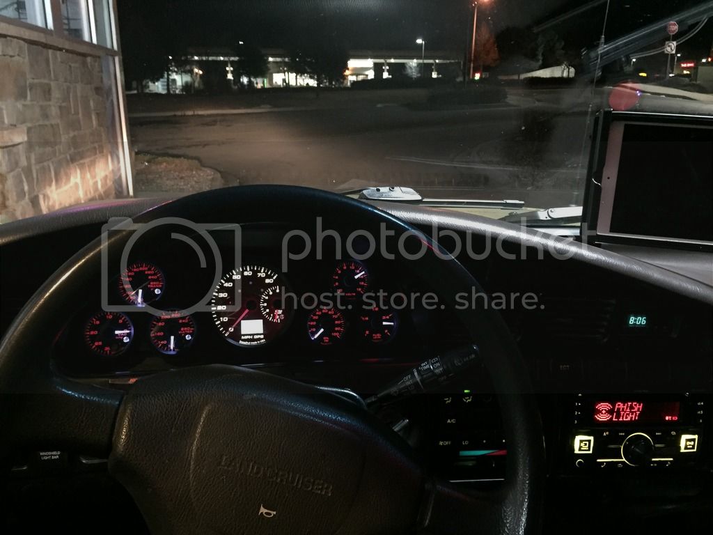
Maybe dial down the backlighting on the dual? I'm guessing the small ones all have a small LED and the dual has larger/more LEDs.

Then again for what you have in it they ought to make it right NQA.
 
Last edited:
Turning the backlight on the dual down doesn't help. After doing some research is sounds like my inverter is faulty. It's only putting out 80-100 vac. It should be putting out up to 200 vac.

Either way the warm white color of the backlight doesn't match the bluish white of the pointers.

From what I read Speedhuts customer service is second to none so we'll see what they say.
 
I'm interested to see these all finished up! I've been wanting to add a couple gauges for tranny temp, vac and cylinder temp..... this looks like THE way to go. Very nice woe so far!
 
The dual's pointers are white during the day time and glow red, I'm sure this is part of the issue but I was led to believe it wasn't a problem.

The gauge face, LCD screen are back lit and on the same circuit as the pointer... I like your suggestion about swapping out the LED's but since these are brand new warrantied items I'm not going to attempt that.
 
So over the last two nights I'd got it set up. Its a rough draft for sure, in hindsight I wouldn't spend the energy cutting out the botton row. Like i said I'm Pretty happy with the trn out.

Layout
IMG_0488_zps58cf9mve.jpg

IMG_0489_zpsj8wvcumk.jpg

IMG_0490_zps6nwaybmc.jpg

Mapping out the circuits
IMG_0496_zpsct6iegcs.jpg

I will clean this up when I do the carbon fiber.
IMG_0502_zpsovkir9yp.jpg

IMG_0491_zpsosfoqlsy.jpg

IMG_0492_zpszovnwmgc.jpg

IMG_0493_zps2d9ye7zr.jpg

IMG_0503_zpsxrbklelh.jpg

IMG_0505_zpsyblp5jqw.jpg
 
That looks very nice, need to publish up that wiring diagram. :)
 
Got it all jotted down on a yellow pad, once I get all the bugs out I'll post it up here. ;)
 
Looks great! Thank you for keeping my OCD 'balance' happy, it looks proper. Some colour adjustment of the centre dial and you are sorted.

BTW, can I make an offer for the centre gear selection indicator module you unplugged if it was the 7 digit version?

regards

Dave
 
Sure thing dave, shoot me a PM. You did the cool back lit idiot light mod in place of the gear shift indicator right?


That's the one, mine being manual it was just a blank space crying out to be used.

status-indicator-jpg.1284245


PM sent.


Regards

Dave
 
Thinking about having a custom dead font panel made for my cluster.

Also does anyone know exactly what the cruise control needs from the combination meter? I don't have cruise control now because I disconnected the feed wires. I've been searching high and low to find if I can just run the speed sensor input to the gauge cluster wire directly to the Cruise CU. When looking at the FSM I see a resistor in the combination meter but when I look at the CC portion of the FSM it says that it the line should give 4 pulses per rotation. Why would a resistor be put in? just to make it a signal voltage?

Screen Shot 2017-01-22 at 2.01.39 AM.webp


Screen Shot 2017-01-22 at 2.02.19 AM.webp
 
So over the last two nights I'd got it set up. Its a rough draft for sure, in hindsight I wouldn't spend the energy cutting out the botton row. Like i said I'm Pretty happy with the trn out.


IMG_0505_zpsyblp5jqw.jpg

Really cool!!
 
If you replace your speedometer you will need to build yourself a circuit condition in order to get the VSS speed signal to the ECU, TCM and Cruise Control Brain. This only applies to the OBD 1 rig, You will need to add the resistor for the OBD 2 rigs so you can modify the diagram below by just removing the Zener Diode from it.

Just bypass the speedometer. See my post here:
Need Help from Electrical Gurus
 
Last edited:
DANG!

That's a super nice gauge cluster setup. Super clean. Super functional. Super expensive.

Can I borrow a dollar? :hillbilly:
 
So I'm working through the VSS to ECU issue in a separate thread here:
Need Help from Electrical Gurus

In the mean time I'm working on my drive indicator with the help of a good friend.
IMG_0661_zpsckxwj8ci.jpg

IMG_0662_zpsvmfgqnb7.jpg

IMG_0663_zps3lo6padd.jpg

IMG_0664_zpskfoyqfn4.jpg

IMG_0665_zpsn8iu4k2c.jpg


I'll see if I can make the solid works file available to everyone via this thread.
 
Light box is nearing production

I added a white LED to each section to illuminate when the parking lights are turned on. I need to figure out how to build a circuit that will turn off the white led when the other LED in that box is turned on. @landcrshr?

And just to note, the front axle LED will be red not green.

light%20box%20Page%20003_zpsxcrrzttj.jpg

light%20box%20Page%20002_zpscymbub8e.jpg

light%20box%20Page%20001_zpsuwbvlxgi.jpg

light%20box%20Page%20004_zps0eyhufv5.jpg

light%20box%20Page%20005_zpsiw2xxtrn.jpg
 

Users who are viewing this thread

Back
Top Bottom