Cluster and Gauges 12 and 24V set up
Let's dive into the gauges and start with the differences between the 12V and 24V clusters.
A 24 Volt cluster is the same as a 12V clusters except for:
- The OIL pressure gauge
- A resistor 30Ω 20Watt
- The PCB board
- The light bulbs of course
Here is a pic which explains the above mentioned exceptions.
I used my gauges ('73 till end '78) for this example.
The 12Volt set up:
The OIL and FUEL gauges are getting 12Volt from the ignition key.
The FUEL gauge has a build in Voltage Regulator which reduces the voltage from 12Volt to 7Volt for the FUEL and the TEMP gauge.
The AMP meter is seperatedly wired between the alternator and the battery. More about the differences in AMP gauges between this one and the later one (for '79 and later) in a later posting.
Now the 24Volt set up:
The OIL gauge gets 24Volt from the ignition key.
The FUEL gauge gets 12Volt from a dropper resistor.
The dropper resistor gets 24V from the ignition key.
The FUEL gauge has a build in Voltage Regulator which reduces the voltage from 12Volt to 7Volt for the TEMP gauge. Same story as above.
The AMP meter is seperatedly wired between the alternator and the battery. More about the differences in AMP gauges between this one and the later one (for '79 and later) in a later posting. Same story as above.
How does that look on the back of a cluster?
The arrows shows the track where the OIL and TEMP gauge both getting their 12V.

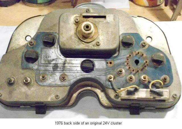
This is how a 24V cluster looks.

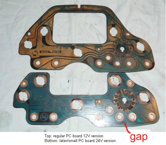
Here you see the gap in the track, so that the OIL gauge gets 24V and from there the resistor reduces the voltage to 12V for the FUEL gauge.

This is a 24V cluster modified for 12Volt. The resistor is removed and bridged by a piece of wire.

Of course you have to replace the OIL gauge for a 12V type (or not?). More about this in a later posting.
Rudi


 Would you be able to make those decals out of white stickers? I would think that there would be some demand for those.
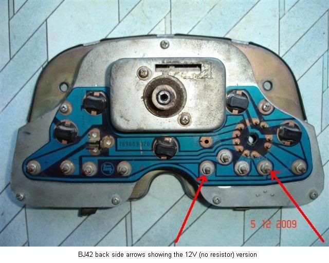


")