Clusters, Gauges, Speedo & Odo meters

This site may earn a commission from merchant affiliate
links, including eBay, Amazon, Skimlinks, and others.

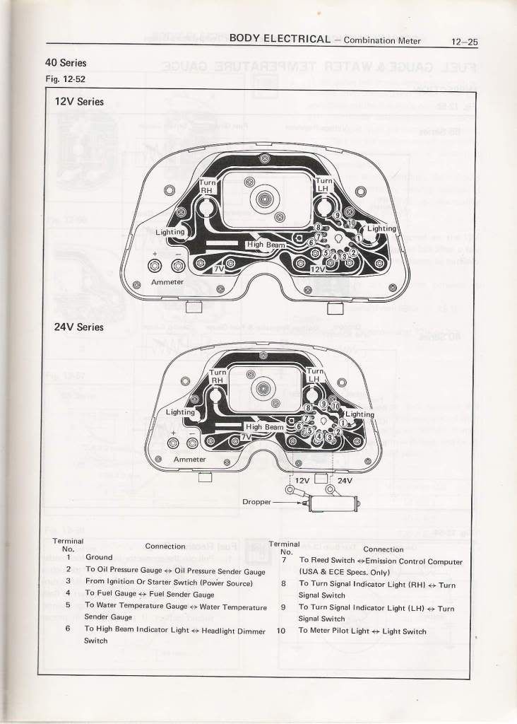
BJ40 Body Electrical FSM


Hello Rudi, thank you very much for sharing all this information. I have a long time looking for a post like this[FONT=&quot] (with details, pictures, etc)
[/FONT][FONT=&quot]
I am looking for the complete FSM of electrical body (the one you used to explain how to fix the cluster gauges) I cant find it anywere and need info about the hazard switch, back up switch, etc… and maybe you have or know where this can be found. My TLC its a BJ40 ´75 with 24V electrical system.
[/FONT]
 
First - great post
Second - sorry for the dumb question in advance

I have what I assume is 2nd generation 10/70 on my 40. Trying to make sure I understand the simple instructions to test with 3.4W bulb...

Installed, there are two posts for each gauge on the back of the cluster. I jumper 12V to one of them, then the other post is jumpered to one side of a 3.4W bulb, and then the other side of the bulb is jumpered to ground??

The result of a working gauge is that it moves and the bulb illuminates? So the bulb is just a load on the circuit to draw current through the gauge?

Now the even dumber question: when I look at the back of teh cluster how do I know which post is for 12V and which goes to the sensor (or bulb)? I don't think they are marked, are they?
 
Sorry for the question, but why at some clusters there was a note and/or "yellow" of 55mph? I think that FJ40 is capable of doing more then 55mph. What the max speed you can do on 2F?

Another question, FJ40 never had a tachometer, at least here in Canada. I remember many vehicles at that time had a markings of maximum speed at each gear marked on the speedometer, but I don't see anything on FJ40 speedometer. As a side question, does someone knows what those speeds are for 4-speed?
 
55mph was the maximum speed limit on US highways back in the day... Remember the Sammy Hagar song "I Can't Drive 55"?
 
First - great post
Second - sorry for the dumb question in advance

I have what I assume is 2nd generation 10/70 on my 40. Trying to make sure I understand the simple instructions to test with 3.4W bulb...

Installed, there are two posts for each gauge on the back of the cluster. I jumper 12V to one of them, then the other post is jumpered to one side of a 3.4W bulb, and then the other side of the bulb is jumpered to ground??

The result of a working gauge is that it moves and the bulb illuminates? So the bulb is just a load on the circuit to draw current through the gauge?

Now the even dumber question: when I look at the back of teh cluster how do I know which post is for 12V and which goes to the sensor (or bulb)? I don't think they are marked, are they?

Thanks for the kind words. The method you describe is right. They are not polarity sensitive so either way is OK.
And yes you're right the bulb acts as the sender.
BUT......... the testing procedure as described in the FSM is for the 3rd generation clusters. I have no expierence with testing the 2nd generation clusters so I'm not 100% sure if the 3.4W bulb will do the trick.

Good luck and Happy Driving

Rudi
 
Last edited:
I wont know until next weekend, but after I test it I'll post results here for the knowledge database.

Thanks
 
ok, showing my ignorance...

Are the individual sending units themselves (temp, oil, fuel) grounded when inserted and installed? So there is only one physical wire that goes from the sending unit to the gauge?

embarrassed :o
 
The answer is yes. There is only one wire from the sender to the gauge.
Stop making excuses and being embarrassed. There are no dumb questions. It is dumb to not ask a question.

Rudi
 
Last edited:
Hi folks

I recall some oil senders posted up on ih8mud that are fitted with a male spade terminal (spot welded onto the body) for an earth wire but the only pic I can find right now doesn't show any wire connected to it.


Earth tab.jpg

Presumably the tab is there to maintain a good earth should the sender be installed with thread-seal-tape on the mounting threads.

Cheers
Tom


(And this explains why I think it is better to use thread-seal-goo rather than thread-tape when mounting senders that aren't separately earthed.)
Earth tab.jpg
 
Last edited:
I need to make my fuel guage work. i'm tired of constantly knocking on the tank, and keeping a spare gerry can.
 
I need to make my fuel guage work. i'm tired of constantly knocking on the tank, and keeping a spare gerry can.

What'is keeping you from doing it?

We are here to help you.

Rudi
 
Wow! This thread just saved the day. I was about to just go and buy a whole new wiring harness to figure out my electrical problems, however like usual mudders always save the day. Hopefully this information will give me the boost to figure this stuff out. Thanks alot to all of you who post great info and are patient with all the ?'s.
 
The TEMP gauges

Hello to all. After a short wintersleep (in the tropics) I'm back again.

So far we've done the OIL and FUEL gauge, now it's time for the TEMP gauge. There is not much to tell here. How it works is described in posting #7 so I only have some electrical info here.
The typical resistance of the gauges is 25Ω.
The resistance of the sender for 09/73 and later is:
60Cº/140Fº = 90Ω
80Cº/176Fº = 50Ω
100Cº/212Fº = 27Ω
105Cº/221Fº = 23Ω
I assume that these values equals the markings on the face plate. Makes sense to me.

1969 temp gauge.jpg till 09/73 S_DSC06692crop.jpg 09/73 till 12/78 coolfj40_2149_509888911crop.jpg 01/79 and later

I have no info on the years till 09/73 so if anyone can help me, please let me know.

Rudi

1969 temp gauge.jpg


S_DSC06692crop.jpg


coolfj40_2149_509888911crop.jpg
 
Last edited:
The AMP gauges / meters till dec '78

The last one in our cluster is the AMP meter or ammeter as Toyota calls it.
How it works is described in posting #7.
In the FSM wiring diagram it looks like this:
ammeter diagram till end '78.jpg

Some tips:
- Pay attention to the fact that the full charge / discharge current goes through the wiring and through the firewall!
The studs on the back of the cluster are not isolated so........
- Disconnect the battery before you remove your cluster!
You're not the first (or the last) who fries his wiring while taking out the cluster.
1969 amp gauge.jpg
till 09/73
S_DSC06680crop.jpg
09/73 till 12/78

There is not much to tell so let's move to the '79 and later ammeter in the next posting.

Rudi

S_DSC06680crop.jpg
 
Last edited:
The AMP gauge / meter '79 and later

coolfj40_2058_261890287 crop.JPG
'79 and later.

From jan. '79 Toyota changed the Amp meter circuit into this:
ammeter diagram '79 and later.JPG

Here the AMP meter is actually a milivolt meter that reads the voltage drop over the fusible link.
Since I can't find a FSM where is written how it works, we have to do some theory here.
Our Mud member Lostmarbles/Tom did some research in his thread https://forum.ih8mud.com/40-55-series-tech/378105-ammeter-fusible-links-late-model-40-series-4.html and he figured out that the AMP meter is a 300 mV meter. Or you can say a 300 - 0 - 300 mV meter calibrated into 50 - 0 - 50 AMP meter.
He meassured that 0,17 Volt (170 millivolt) moves the needle to about half the value of the scale so that's 25Amps.
Ammeter0_3Vfullscale.jpg


I've read many threads that say: " my '79 and later ammeter doesn't show any movement".
The question is, why is that? Is it a bad design or is something else wrong?
Let's have a look at the diagram. The first thing that stands out is the two 5Amp (glass type) fuses.
Why are there 2 (two) fuses in series with the ammeter?
I can think of only one reason..... Toyota learned from their previous design and added those fuses for safety reasons.
Remember that in the previous design there was only the fusible link from the battery in series which would blow (after some time) if there was a short in the wiring by chafing to ground or by taking out the cluster and touching ground with the ammeter studs.
Back to the question; why is the ammeter not showing any movement?
I need some help from you Mud members to get some answers on my questions to figure out if it's a bad design or is there a problem that we can solve without altering the design.

I like to have readings on the following questions because I suspect that there is a problem in the in-line fuse box.
1. How much is the voltage over the fusible link but meassured at the in-line fuse box, when the headlights are switched on?
2. The same reading but now on the downstream side of the fuse box.
3. How much is the voltage over the fuses when the headlights are switched on?
I'm curious how much voltage drop/loss is in that in-line fuse box.
This can certainly influence the ammeter reading.
Thanks in advance for the help.

Rudi
 
Last edited:
bj40green said:
Some tips:
- Pay attention to the fact that the full charge / discharge current goes through the wiring and through the firewall!
The studs on the back of the cluster are not isolated so........
- Disconnect the battery before you remove your cluster!
You're not the first (or the last) who fries his wiring while taking out the cluster.
I have made several attempts at welding my cluster to the dash :lol:

Great thread :cheers:

Sent from my thing with Woody's junk.
 
View attachment 603845 '79 and later.

....I need some help from you Mud members to get some answers on my questions to figure out if it's a bad design or is there a problem that we can solve without altering the design.

I like to have readings on the following questions because I suspect that there is a problem in the in-line fuse box.
1. How much is the voltage over the fusible link but meassured at the in-line fuse box, when the headlights are switched on?
2. The same reading but now on the downstream side of the fuse box.
3. How much is the voltage over the fuses when the headlights are switched on?
I'm curious how much voltage drop/loss is in that in-line fuse box.
This can certainly influence the ammeter reading.
Thanks in advance for the help. .....Rudi

As you know, my ammeter-shunt fusible link isn't OEM but I tried to match the OEM dimensions as close as I could Rudi.

And I've just now unwound the electrical tape from the little fusebox (for the twin ammeter fuses that Toyota placed in the loom near the + Ve battery terminal), opened the fusebox up, and performed some voltmeter tests there for you.

At first I just turned on the headlights as you suggested (with the engine off) but that only registered a voltage drop across the fusible link of 0.01V.

So then I turned the "ignition switch" to "On" and turned the heater-blower fan on full (still with the engine off and with the headlights turned on).

This showed a higher voltage drop across the fusible link (measured by having one probe on one fuse and one probe on the other) ... but it was still just 0.02V. (Not enough to get my ammeter to move.)

And I couldn't detect any voltage drop across either fuse individually (bearing in mind that my voltmeter sensitivity is just 0.01V).

:beer:
 
If it the 300mV/50A figure is correct, then you need a fusible link with a total resistance of 0.006 ohms to produce that voltage.

Tom's old thread shows the link wire has a cross sectional area of roughly 2.0 sq mm (its printed on his replacement wire, helpfully), which means its about 1/16" (or 1.6mm) diameter... aka 14 gauge.

14 gauge wire gives you ~.004ohms per foot, so to get the 0.1ohms you need to produce proper needle deflection the link MUST be a full 1.5 feet (45cm) long.

Obviously the OEM link wasn't that long, so there is a problem with the 300mV number.

Another way to look at it: Tom found the OEM link to be ~3" long. A 3" wire with the proper .1ohm resistance would need to be 24 gauge, or .02"/.5mm diameter. Obviously that is VERY small for this usage and cannot be correct.

I suspect that Tom's measurement is accurate for his meter, but that the magnet inside the ammeter has lost its strength with age. I'll go try and experiment and post back in a couple hours...
 
By bj40green:
Why are there 2 (two) fuses in series with the ammeter?
I can think of only one reason..... Toyota learned from their previous design and added those fuses for safety reasons.
Remember that in the previous design there was only the fusible link from the battery in series which would blow (after some time) if there was a short in the wiring by chafing to ground or by taking out the cluster and touching ground with the ammeter studs.

I had a PM with Lostmarbles/Tom and he added to the above mentioned fuses:
" Both sides (of the ammeter wires) are at full-battery-voltage potential (12V or 24V depending on your cruiser model) relative to your cruiser's chassis/bodywork."
Thanks Tom for adding this.

By Amaurer:
If it the 300mV/50A figure is correct, then you need a fusible link with a total resistance of 0.006 ohms to produce that voltage.
Yes, I figured that out too. 6 milliohm to produce 300mV at 50 Amps.
If we take the 300mV = 50 Amps as the numbers we can calculate that:
200mV = 33.3Amps, 100mV = 16.7Amps and 50mV = 8.3Amps.
Now take the readings from Tom; 0.020V or 20mV with headlights, blower and ignition on and this will calculate to 3.3Amps which is a very little number to show needle movement on a 50 Amp scale.
But..... calculating the other way: 2 headlights 50W each = 100Watts, 4 running lights 5W each = 20Watts, totals 120Watts divided by 12Volts = 10 amps! 10Amps is one 5th of the 50Amps scale so that needle movement should be visible.

:hhmm: I'll take a brake, coffee time!

Rudi
 
But..... calculating the other way: 2 headlights 50W each = 100Watts, 4 running lights 5W each = 20Watts, totals 120Watts divided by 12Volts = 10 amps! 10Amps is one 5th of the 50Amps scale so that needle movement should be visible.

Yes, absolutely.

Stay tuned... ;)
 

Users who are viewing this thread

Back
Top Bottom