
- Thread starter
- #21
On a side note, after adjusting valves and tweaking carb, I'm now pulling a steady 21" at idle.
Follow along with the video below to see how to install our site as a web app on your home screen.
Note: This feature may not be available in some browsers.
This site may earn a commission from merchant affiliate
links, including eBay, Amazon, Skimlinks, and others.
For those at altitude like me (7,240 feet) the sea level vacuum adjusted for altitude is only about 15.2", so I'm doing good when I hit that point.21" is what mine pulls at idle too (sea level, overhauled head with new everything, flat manifold & new gaskets).
That's something, an open vacuum pipe like the AC idle up fitting only drops the vac 1". And that's a big vac leak. My engine doesn't sound quite right when I pull that hose (playing around). Only 1" drop & somethings not right.
Something to remember...
Done.
That's the set-up for venting your distributor cap. I'll try to dig up the diagram from the FSM. IIRC the large hose coming out of the side should attach to the top of the distributor cap, the large hose coming out of the top (via the tee) should attach to the underside of the air filter housing, and the bottom vacuum hose should connect to the gas filter fitting on the top of the intake manifold.Thanks CJ!
I’m in the process of searching and correcting vacuum leaks and I came across this valve with a strange set-up which I have not been able to verify in the FSM.
Can anyone guide me on how the set-up should actually be, if this is incorrectly connected - appears to be connected to itself.
View attachment 1557926
4cruiser's drawing is correct as per the FSM drawing pg 3-3 of the Emission Manual.
I have had mine hooked up with a T on X and Z with Y going to the air cleaner this whole time. Taking a closer look at this led me down another rabbit hole. After sleuthing, I'm keeping my setup as is.
The VCV
That's a great diagram.However if you look at the vacuum diagram via the parts diagram, it is not the same. Mine has been setup according to the diagram below.
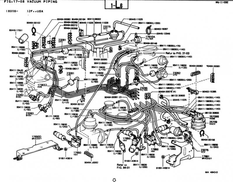
However if you look at the vacuum diagram via the parts diagram, it is not the same. Mine has been setup according to the diagram below.