B engine compression & leakage testing along with glowplug & injector replacement

This site may earn a commission from merchant affiliate
links, including eBay, Amazon, Skimlinks, and others.

Page 8-4 and 10-25 of this manual:

View attachment 264291

:cheers:

My copy of that FSM gives the numbers on page 8-4 and 10-23.

I also have a FSM dated AUG 1980 which covers B, 2B, 3B engines, it says 0.2 ohm for 12V systems on pages 8-5 and 10-30.

Values for 24V systems are on the same pages.

I also have a FSM dated MAR 1986 that does not give a resistance value for the glow plugs, just says to check for continuity, also says to "Be careful not to apply more than 7 volts to the glow plug as it could cause an open circuit."
 
Ok here's my glow plug numbers for my 81 bj42 (24 volt model) this is a manual glow system no timer

Around 18 volts to the plugs during the cycle
At the start of the cycle over 24 amps
At the end of the cycle about 20 seconds less than 17 amps and falling
Measured resistance at each plug about 3 ohms.

Not sure where the 12 volt system current would be, but probably not much difference??

Cheers
 
Ok here's my glow plug numbers for my 81 bj42 (24 volt model) this is a manual glow system no timer
Around 18 volts to the plugs during the cycle
At the start of the cycle over 24 amps
At the end of the cycle about 20 seconds less than 17 amps and falling
Measured resistance at each plug about 3 ohms.
Not sure where the 12 volt system current would be, but probably not much difference??
Cheers

Thanks heaps Freebie.

Based on this comparison from my FSM:

manualB2B.webp

Edit: Oct/09 Finally realised the FSM plug current data above is PER PLUG. So these figures aren't as silly as I thought at the time! :o

I wouldn't expect the current draw to be the same. I suspect I have up to double your current figures. (That's 48A initially lowering to 34A after about 20 seconds. But more realistically - probably 45A lovering to 30A?)

I'm sure one of us with a 12V cruiser, manual glow system and 8.5V plugs will have a suitable ammeter to be able to confirm/refute this in the not-too-distant-future.

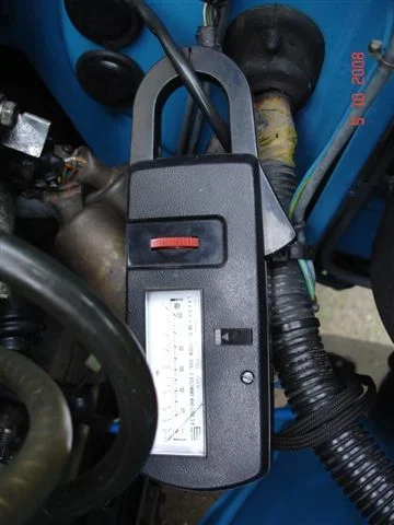
Meanwhile I've tried my clip-on (clamp-on) ammeter but the needle just twitches when my son turns on the glow circuit:

5 Oct 004.webp


I didn't expect it to work because all the literature that was supplied with this meter related to testing AC circuits (not DC).
manualB2B.webp
5 Oct 004.webp
 
Last edited:
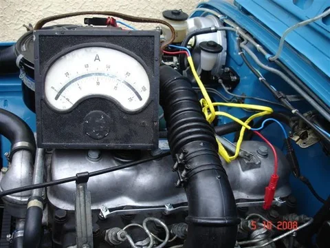
Just for amusement (and because it is dizzling outside and too wet to lift the rocker cover) I rummaged through my junk and found a few other interesting things. (I'm a hoarder from way-back and have always had a fetish for anything that has a "dial and pointer". So I have lots of old clocks, barometers, bla bla bla, and even a few ammeters.)

This ammeter jumped right across the scale:

5 Oct 001.webp

Not surprising I guess cos I'm sure it's meant for AC only.

And this one did the same:

5 Oct 003.webp

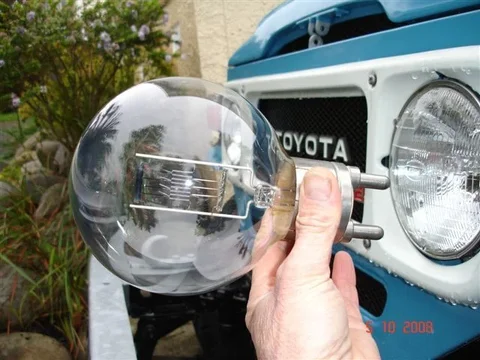
Hey - I bet I would have good headlights if I wired up this 1000 Watt globe!

5 Oct 005.webp
5 Oct 001.webp
5 Oct 003.webp
5 Oct 005.webp
 
There's been something else I've been wanting to test for some time so I thought I'd do it here and now . (The drizzle has stopped but my blood-alcohol level is too high to go for a drive to warm the engine up for tappet adjustment just yet!)

I know a lot of mud members already know exactly how their EDIC behaves - but I've always wanted to test mine for myself. ---- In particular - how it's responds to low oil pressure.

So I disconnected the "oil pressure cutout switch" here:

edic 001.webp

And with this disconnected, I've just confirmed that the cruiser starts and runs exactly as per normal. (In other words - all I've done by disconnecting that switch is remove my engine's "low oil pressure protection".)

Now if, once my engine is running and I "ground" that connector..... Let's see.................Ah yes. The engine dies almost instantly as the EDIC moves the injector pump lever to the "stop" position. (Just what I expected.)

edic1.webp

This confirms to me that the oil pressure switch must open when the engine's oil pressure reaches a set level and then close again whenever the oil pressure is lost (or falls below a set level - which I seem to recall from others is around 7 psi).

Oh my God! This thread is wandering all over the place. ----- (That's cos my disturbed mind tends to do that:D)
edic 001.webp
edic1.webp
 
Then I scrubbed it with a touthbrush and a product here called "Jiff" which is just a household cleaner used to clean smooth surfaces like those in baths, shower cubicles and sinks. (A white creamy liquid that feels like it is a "suspension of grinding-powder".)

Do they still call it Jif across there, or is that a bottle you've had knocking about for a few years? :D Scotch-Brite pads, (or similar), also work extremely well for removing gunge and oxide from surfaces.
 
Further on this hijack-theme of checking out the EDIC behaviour in connection with the oil-pressure-cutout-switch................

With my ignition key on (engine not running) and the oil pressure switch disconnected my EDIC has the injector pump lever in the "run" position.

edic 003.webp
edic 004.webp


With my ignition key on (engine not running) but the oil pressure switch connected my EDIC has the injector pump lever in the "stop" position.
edic 002.webp

So disconnecting and reconnecting the oil pressure switch (while the ign key is on yet the engine isn't running) will cause the EDIC to move the injector pump lever to the "run" and "stop" positions (respectively).

End of this hijack (but there may well be more). Hey ... Tech is really just "tech chat" anyway.
edic 003.webp
edic 004.webp
edic 002.webp
 
Last edited:
Do they still call it Jif across there....

Yep we do Matt. (I've just bought another squeeze-bottle of it at the supermarket.)

And you were right to correct my spelling. It DOES have only one "F". :D
 
Yep we do Matt. (I've just bought another squeeze-bottle of it at the supermarket.)

And you were right to correct my spelling. It DOES have only one "F". :D

:D It's one of those names which is stamped in our memory over here. :D

The sods changed the name of it over here a few years ago to Cif though. It's been Jif since the 70's, and they decide to go and change the name. No idea why. Damned good stuff for cleaning/scouring jobs though. :D
 
Well. We had our ration of sunshine for the day. (Less than an hour.) Back to drizzle now. Anyone would think this was Ireland or the Yorkshire Moors instead of NZ! :hhmm:. ... No offence meant to the Irish either. I actually like moss and the colour green. None of us suffer bush fires either! And I know the Yorkshire Moors is lot more than just a place where bodies are buried.:))

No chance of doing the tappets now. It's almost 4pm and I'm cooking tea tonight because :princess: has had enough of me and run away to her mother's (way up north) for a week! (Yeah. So you're right. I'm actually cooking tea all week!)

Time enough to get another cruiser job out of the way today though. ---- Or perhaps "out of the way" is being too optimistic considering how long I have been working on this task.

See this pretty braided stainless hose here : (The larger of the two)
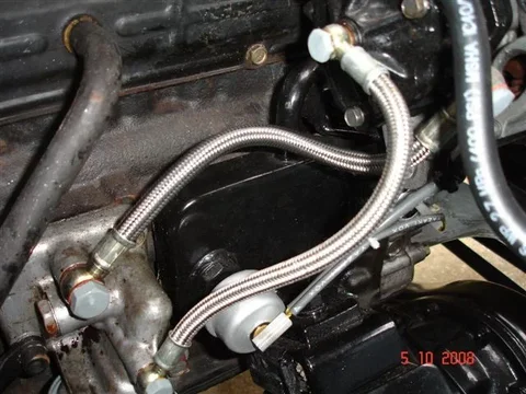
braided 001.webp

It keeps dripping dirty black engine oil on top of my lovely oil filter housing like so:

braided 002.webp

And that hose is a bit like the "rogue taps" that another age-compromised colleague used to ramble on about. (A rogue tap is one that defies all attempts at stopping it from dripping and shows no sign of any wear /damage that may be causing the drip!)

I have had that hose immersed in water under air pressure and seen no sign whatsoever of bubbles! I've also swapped from copper washers to fibre ones at the banjos in yet another futile attempt at stemming the oil seepage.

So this last week (in desperation) I ordered a complete replacement hose at the huge expense of $61.59 NZ.

braided 003.webp
(The twisted hose is the old one -or old new-one - that I suspect of leaking.)

All my previous braided stainless hoses from this outfit were made up with teflon inner hose which is pretty stiff and unflexible really. (They reckoned it was the best material back then.)

This time I asked them to get the "same degree of twist" between inlet and outlet banjos (because I remember having quite some difficulty twisting the previous teflon hoses to get them to fit).

Anyway - Now they have mysteriously supplied me a "rubber Auto Flex" inner hose instead of teflon. (Actually feels much better because it flexes far more easily.) And they used the banjos from my sample hose (the original ex-factory Toyota ones) saying they couldn't obtain new ones in that sizing. (Strange! They obtained them OK before?)

Since they destroyed my sample hose - I no longer had a hose to compare the new one against to ensure they got the length and "banjo twist" correct. (Cunning bastards!)

And in case anyone wonders why I PAID to get a replacement hose for one that I suspect of being faulty (rather than asking for a replacement under warranty) - the reason is because I couldn't confirm the leak (with the immersion testing) and therefore I can't garantee that they supplied a faulty product. (Another way of saying this is that "I don't have full confidence in my opinion that their hose is leaking".)

So now the new new-hose is fitted and I've gone back to using copper washers on the banjos. And as I've been typing this - the cruiser's been running in the driveway (annoying the neighbours). - So far there's no sign of any oil weepage but it is very "early days" yet.

Fingers crossed. :D
braided 001.webp
braided 002.webp
braided 003.webp
 
Last edited:
Ok here's my glow plug numbers for my 81 bj42 (24 volt model) this is a manual glow system no timer

Around 18 volts to the plugs during the cycle
At the start of the cycle over 24 amps
At the end of the cycle about 20 seconds less than 17 amps and falling
Measured resistance at each plug about 3 ohms.

Not sure where the 12 volt system current would be, but probably not much difference??

Cheers

I've been thinking a bit more about your results.

I'm guessing you're running 20.5V plugs here. - Right?

And I guess you noticed your busbar voltage increasing as your plugs heated up. - So was your "18V" figure obtained at the start or end of the glow period? (My figure was measured at the end - and you can see that my measurement pretty well matches my glowplug voltage" rating of 8.5V.)
 
..... also says to "Be careful not to apply more than 7 volts to the glow plug as it could cause an open circuit."

My guess is that this warning is meant to apply to the 6V plugs used in 12V cruisers that employ "superglow" Wayne
 
I've been thinking a bit more about your results.

I'm guessing you're running 20.5V plugs here. - Right?

And I guess you noticed your busbar voltage increasing as your plugs heated up. - So was your "18V" figure obtained at the start or end of the glow period? (My figure was measured at the end - and you can see that my measurement pretty well matches my glowplug voltage" rating of 8.5V.)


Not sure which plugs I have but 20.5 V sounds right ( don't think I even looked at them when I swapped them onto this motor) but they should be correct for my model and year.
As far as I could tell my voltage stayed around 18 volts during the whole cycle, but I was watching the current change rather then voltage change.
Either way the numbers seem to work out close enough, given the engine was more or less at operating temp and the start and end current will vary with the start and end temp.

Cheers
 
and, my manuals and wiring diagrams are for the newer 83 models, so the glow system does not match my system. The do not exceed 7 volts was also in my 83 manual, but no mention of resistance. which makes sense, for the ohm value to be exact, the temp of the glow plug would have to be at a set value.
 
The weather doesn't get any worse than it is here today! Gale force winds and rain. And it is "rubbish collection day" so as I type this I can hear all the rubbish/recycling blowing down the street. (Already been out twice trying to clean it up :mad:)

But yesterday was a different story. I got to adjust the tappets before I had to go off to work. (Ran out of time to repeat the compression testing though.)

But that work has raised some serious concerns within me about whether I know what I'm doing.

Last time I "adjusted tappets" was before there was an "Internet" so I couldn't get people to point out what I was doing wrong. Now I can:)

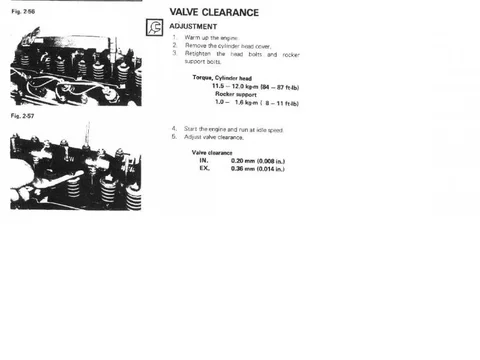
Anyway - This is what the B/2B FSM had to say about doing the job:

B2BFSM.webp

That is not at all helpful for a dumb-arse like me!

I'm blowed if I'm going to adjust my tappets with the engine idling! I can just imagine the black engine oil running everywhere, the tappets "grabbing" my feeler gauges, the tappet movement causing me to butcher the adjustment locknuts, etc.

So I felt I had to devise my own method - bearing in mind that I can't determine piston TDC using my traditional "knitting needle down the plughole" trick.

So I decided to check/set the clearances simply when I knew a piston was "close to TDC on its compression stroke" which I determined by watching the behaviour of the cylinder's inlet and outlet valves as I rotated the crank.

In other words, I watched the inlet valve open and then reclose, and then watched till both valves on that cylinder were closed. I then measured the maximum tappet clearance (WHILE BOTH THOSE VALVES REMAINED CLOSED) - moving the crank as necessary to find this "maximum clearance" point.

Was this an acceptable method?????

I'm unsure because I notice that there are other points where the clearances are even greater.

Anyway - Doing it the way I describe with the engine still hot after a good run - these are the figures I got - in thousandths of an inch (with the correct clearance in brackets):

No. 1: ......Inlet 14 (8) ...... Exhaust 19 (14)
No. 2: ......Inlet 16 ........ Exhaust 19
No. 3: ......Inlet 13 ....... Exhaust 14
No. 4: ......Inlet 20 ....... Exhaust 15
B2BFSM.webp
 
Last edited:
Oh.... By the way..... I forgot to mention that I did have a go at retorquing the 18 headbolts before doing the tappets. (Supposed to work diagonally outwards from the centre as you torque them.)

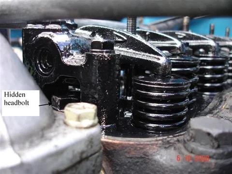
Trouble is, some of the headbolts are inaccessible without removing the rocker assembly:

Tappets 001.webp

So I just set my torque wrench on the max torque setting (120 Newton-metres) and tested those that were accessible:

Tappets 002.webp

(PS. - I had to use the other hand for the camera. Normally my other hand would actually sit on top of the torque wrench above the socket.)

Since none of them moved at that torque setting - I figured there was no need to remove my "rocker assembly" and retorque the hidden ones. (But I admit - Those bolts may all be refusing to move simply because they are locked/seized in their threads rather than because they are exerting the correct clamping force on the head.)

Now as far as the 10 "rocker support bolts" are concerned - At first I checked those with my torgue wrench on the max (16 Nm) setting and nothing moved. (Supposed to work outwards from the centre again but this time "in pairs" rather than "diagonally".) Then I thought this torque specification felt "too light" so I used an ordinary bar and torqued them (to what "felt right" to me). When I did this - They each made a loud "crack" as they broke free, and then easily turned (probably 1/4 of a turn or more). (:hhmm: Wonder if the head bolts would have done the same.)

Sorry Drew - As you can see. I've decided against removing the rocker assembly to look for "legendary divots". (I'm supposed to be working on painting the body/chassis and not doing any of this anyway :D)

Oh - And I also forgot to mention that there isn't a problem in finding TDC for number 1 piston. - I just rotated the crank in its normal rotational direction till I saw from the valves that it was on a compression stroke and then aligned the pointer with the second mark on the crank pulley so:

Tappets 003.webp

But as I say - I was happy to move the crank from TDC to find the point where I got "maximimum valve/tappet clearance" SO LONG AS I DIDN'T MOVE IT FAR ENOUGH TO CAUSE EITHER VALVE TO OPEN.

What does everyone think? Did I stuff up? (And if so, how should I have done it? .......And DON'T tell me I should have set them while it was idling. :D)
Tappets 001.webp
Tappets 002.webp
Tappets 003.webp
 
You are supposed to do it with the engine idling, it does not get oil everywhere, it is a hassle and eats up feeler gauges unless you have hardened blades. I did it this way once. Usually I do it like you do - engine warmbut shut off, watch the valves to see when you are on compression stroke and try to find a point where both cam followers seem to be on the bottom of the cam lobes. Doing this at 10,000km intervals seems to be overkill, I usually find nothing needs ot be adjusted. Mind you, I haven't done it for years (200,000km?) so I guess it is time.

I just looked at my 1986 FSM. it has an easier method, engine warmed but stopped. I will scan the page and post it here.
 
Here is the valve clearance checking page from the March 1986 FSM for B, 3B, 11B,13B, 13B-T engines. Hope this helps.
valve clearence.webp
 
Wow. That's interesting - Thanks a lot Wayne.

I had actually seen similar stuff in my manual in the section that covers "reassembly" and there they used the word "tentatively".

Here - I'll show you:
tentat1.webp

tentat2.webp

So I had assumed (from that word "tentatively") that that method was just a preliminary way of getting the tappets adjusted "more-or-less right" after a head has been completely dismantled/overhauled. (Convenient because you only need to put the crank in two positions in order to set all 8 tappets!) I then thought that once you got the engine completely assembled and running (with the headbolts retorqued)- you adjusted them properly. (IE. using a more accurate method)

But your FSM version refers to "hot clearances" (and an engine isn't hot when it is on the workshop bench).:frown:

:hhmm::hhmm::hhmm:

So what I surmise from all of this is:
  • If my FSM says to adjust the tappets "at idle" then the position of the crank can't be vital. Because all you could do in that situation is see if a feeler gauge is able to slip into a gap "at some point during the camshaft's rotation".
  • All FSM data I've seen talks about setting the tappets on No. 1 cylinder while both its valves are closed and while its piston is at TDC - So this same procedure MUST then also be acceptable with any other cylinder. (The trouble being that you can't easily ascertain TDC in the other cylinders.)
  • I shouldn't really worry about the fact that I can fit a LARGER feeler gauge into a "tappet gap" at some point during the camshaft's rotation other than when both valves are closed on a compression stroke - because this is probably caused by camshaft wear (where a camfollower tends to hit hardest after coming off a lobe)
  • Bearing all of this in mind - the method I used MUST be acceptable. (In my way of thinking!)
Anyway - At present I am fairly confident I have all my tappets adjusted within 1 thou of the 0.008"(inlet) and 0.014"(exhaust) specification using "my chosen method".

PS. I used imperial (inches) because my best set of feeler gauges are calibrated in "old inches".

So if I can get around to it - I'll also try and see what size feelers are able to fit into the specified tappets in those 2 crank positions (as an experiment).

I'd also like to experiment with seeing the differences between "hot" and "cold" measurements (to see if there really is a difference).

And - thinking about it - I accept that if I were to adjust my tappets at idle - most of that dirty black oil should still run down into the crankcase rather that run elsewhere........ Except I'd have to park on more level ground and NOT in my sloping driveway. (But I'm still NOT going to do it.)

Oh s***. If you're thinking I've rambled on enough (and am being toooooo anal) right now. But w-a-i-t .............there's more.

As far as the "legendary divots" are concerned - I thought I could check for those by comparing the tappet movement (measured with a dial gauge) against the size of feeler gauge I'm able to insert.

:cheers:

:cheers:
tentat1.webp
tentat2.webp
 
Last edited:
LOL!!
i have yet to see someone set the valves ona running engine.
you bring the engine up to operating temp, shut it down and adjust the valves...
 

Users who are viewing this thread

Back
Top Bottom