B engine compression & leakage testing along with glowplug & injector replacement

This site may earn a commission from merchant affiliate
links, including eBay, Amazon, Skimlinks, and others.

Now you will see that the LH gauge reads around 15 psi. So that is actually the maximum pressure that this tool can apply to any cylinder it is testing! Yep - A measerly 15 psi!!!! But with just 15 psi - the Leakage Tester seems to do a far better job at diagnosing my engine than my Compression Tester did! ( :hhmm: Perhaps I should just say - It is less prone to operator-error?)

Once you have set/callibrated the tool in this way, you then connect it to the cylinder you are testing. And I did this using the hose supplied together with that fitting I made from an old glowplug (shown at the start of this thread).

The results I got were rather alarming (for No.2 cylinder)!

No. 1 - 33% (within "low leakage" band = good)
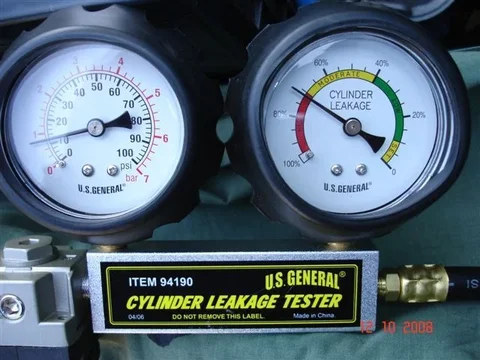
No. 2 - 72% (just into "high leakage" band = bad)
No. 3 - 55% (in "moderate leakage" band)
No.4 - 46% (in "moderate leakage" band)

And I could easily hear the air leaking into the crankcase from No.2 cylinder!

By the way - With the tappet/rocker cover removed, I had no problem getting "each piston near TDC with both its cylinder's valves closed". And I put the gearbox in 4th to stop any engine rotation occuring but I noticed no tendency for that to occur. (Not surprising really because the pressure in the cylinder is under 15 psi).

And I should mention that this tool has some sort of "orifice" inside it. This means that leakage causes the pressure downstream of the orifice (measured by the RH gauge) to fall below the upstream pressure (measured by the LH gauge).

Note: The RH gauge could have been callibrated from 0 to 15 psi but instead (to make things easier for me) it is callibrated in "percentage leagage"

Another thing: - I did notice a tendency for the RH gauge to creep upwards from the "zero mark" when being set/callibrated. (Probably due to a poor quality regulator.) But I found that slight variations in the way I "zero-ed" the tool didn't affect the readings at all. So, in other words, - I have confidence in my readings here.

Here's me checking my "poor" cylinder (No. 2 cylinder):

leakageNo2 1.webp

And here is a close-up of the gauges (No. 2 cylinder):
leakageNo2 2.webp

Now before anyone tells me - YES........... I should have squirted some oil into No.2 cylinder and taken a second reading to see if the % loss reduced to an acceptable level. (This would have proven that rings/bore was responsible.) The fact is - I was unfamiliar with using the tool and I think my decision not to use oil with my compression tester stuck in my mind. (Of course the Leakage Tester wouldn't suffer from ingesting the oil - unlike the Compression Tester - so there would have been no "negatives" associated with doing this "wet test".) ------- But I'm NOT going to open her up yet again to correct this oversight because I have NO intention of getting further into engine-work at this point in time.

Now these "Leakage Test results" made me reconsider my "Compression Testing results". ....:hhmm::hhmm::hhmm: And I now believe the first figures (the poorer figures) were the most accurate.

Here is what the Compression Tester Instructions said:

CompInstr.webp

Now I previously thought the underlined part was "dribble" but in light of my Leakage Test findings, I now believe you MUST put a limit on the number of "compression pulses" that you use to build up to the reading you take with a Compression Gauge. And in retrospect, I believe restricting myself to "8 pulses" for each and every reading would have been appropriate! - Edit 14 Oct - Ignore me here (in this paragraph). This is "garbage".
leakageNo2 1.webp
leakageNo2 2.webp
CompInstr.webp
 
Last edited:
I bought a new gasket for the rocker cover of course:

$49gasket.webp

This gasket contains "less rubber" than the OEM gasket because it is made as an "eliptical-section O-ring" rather than as a "rectangular section".

And since the bastards charged me $49NZ for this gasket and went to all the trouble of shrink-wrapping it - You'd think they would have included the four rubber sealing washers (that go under my dome nuts):

CoverboltGasket.webp

But NO! I was forced to re-use my 29 year-old ones!

(If any of us were running that business I'm sure we would have catered better for the customers' needs!)

But at least I have no complaints about the "sealing ability" of the O-ring. You can see here that it sits "proud" and should do just as good a job as a genuine Toyota product:

RockercoverOring.webp
$49gasket.webp
CoverboltGasket.webp
RockercoverOring.webp
 
Oh - And since a mate on this board cracked his rocker cover when tightening his dome nuts - I decided to use a torque wrench (with my own limit of 3 newton-metres) to avoid doing the same thing:

RockerCover3Nm.webp


By the way - Good news is that my rogue braided hose may have actually stopped oozing oil. I've been doing a lot of running around in the cruiser lately and there is nothing showing there that'll even leave a dirty smudge-mark on a bunch of paper tissues! (That's a leak-test method I've been using!) Give it a month or two and if it's still not leaking I'll call it "fixed".
RockerCover3Nm.webp
 
Last edited:
Now these "Leakage Test results" made me reconsider my "Compression Testing results". ....:hhmm::hhmm::hhmm: And I now believe the first figures (the poorer figures) were the most accurate.

Here is what the Compression Tester Instructions said:

View attachment 266193

Now I previously thought the underlined part was "dribble" but in light of my Leakage Test findings, I now believe you MUST put a limit on the number of "compression pulses" that you use to build up to the reading you take with a Compression Gauge. And in retrospect, I believe restricting myself to "8 pulses" for each and every reading would have been appropriate!

I disagree. The 8 revolutions note really is just for the sake of the starter (and associated liability concerns).

Keep in mind that the cylinder "vents" completely on each revolution when the intake valve opens, so there is no pressure "building up" on each revolution. The only reason it takes more than one spin to read the max amount on the gauge is because the gauge mechanism and needle itself has a certain amount of inertia and can't respond fast enough to the peak value.

If you observe the 8 revolutions rule then the cranking speed becomes a huge variable and readings between vehicles will be all over the place.
 
.....I now believe you MUST put a limit on the number of "compression pulses" that you use to build up to the reading you take with a Compression Gauge. And in retrospect, I believe restricting myself to "8 pulses" for each and every reading would have been appropriate!

:hhmm: I wonder what prompted me to say this? - After all, when I was typing that sh#t I did indeed remember that Amaurer/Drew had decided such a limit was unnecessary/wrong (and remembered too that he had received outside input agreeing with him) in his own recent compression testing thread?

Perhaps I just wanted to prompt more discussion on the subject?

But I think the real reason was because I do feel my No. 2 cylinder is "a little sick" and I was "clutching at straws" in trying to find an explanation for why this was revealed only by the FIRST of my two compression tests.

(:lol: I'm often trying to "self-diagnose" my motivations. ---- Another possibility is that I'm "letting slip" that I really am just an arsehole who likes contradicting others!)

Hey - Maybe I should put all my results together here to enable comparisons to be made more easily:

Cylinders:.............No.1........No.2 ........No.3 ..........No.4
1st comp test:.......400..........340..........360............420
2nd (after tapp adj):440.........380..........380............400
Leakage testing:.....33%..........72%........55%..........46%

(This list may appear all "out-of-kilter" on some peoples' screens because I can't use the "tab key" for alignment purposes here.)

I guess "unusual variations" in the pressure readings could be caused by "natural variations" in the amount of oil present in the bores. (Engine was "hot" for all tests though.)

But this goes to prove that this sort of testing is not an "exact science".

I was looking to see if there was some sort of correlation between the tappet adjustments and the "generally improved" compression figures that were recorded afterwards. (No. 4 cylinder actually suffered reduced compression?) All I could find is that Nos 1 & 2 cylinders experienced the biggest improvements (40 psi) and they were also the ones that were given the "largest clearance-reductions" on their exhaust tappets. I wonder if this is just coincidence?

If I wanted to choose between the testers - I'd go for the "Leakage Tester" over the "Compression Tester". Its results inspire more confidence in me. And I think the way it performs its tests is "basically superior".

I disagree. The 8 revolutions note really is just for the sake of the starter (and associated liability concerns). .....Keep in mind that the cylinder "vents" completely on each revolution when the intake valve opens, so there is no pressure "building up" on each revolution. ....

You're right of course Drew.

Successive compression strokes within a cylinder should each be independantly achieving their own limit (completely independant of the previous strokes). And the air trapped inside your Compression Gauge (and trapped inside the airline leading to the gauge & downstream of the gauge's check valve) is simply "being compressed in pulses" by these cylinder pulses. So a graph of "gauge pressure against time" would look something like this:

graph.webp

(Sorry for the rough nature of the graph)

So I unconditionally withdraw my comment that you should impose a "pulse limit" when using a compression gauge (unless you're doing it to protect your starter motor from overheating/damage).

I am fairly sure that No.2 cylinder is indeed "a bit sick" because the Leakage Tester proves it. And if I'm honest, I'd have to admit that my "blowby" (emitted from my crankcase breather pipe) REALLY is getting more noticeable these days.

I have my theory as to what is most likely to be the cause too.

Doing this thread has made me see (thanks Drew) that I had overlooked "checking/adjusting tappets" in my maintenance schedule (allowing the clearances to become DOUBLE the specification).

Well another thing I have overlooked is "injector maintenance".

I think it is quite possible that a "dribbling injector" or "poor spray pattern" on No.2 cylinder could have resulted in excessive "bore wear" there.

Some time back on MUD, I read someone say that they believed injectors should be serviced (new nozzles, opening pressures adjusted etc) every 100,000 kms. That sounds entirely reasonable to me. So this job is 140,000kms overdue on my cruiser.

Which is why "fitting reconditioned injectors" is the next thing I'm going to do here.

:cheers:

PS. I believe compression results will ALWAYS be affected by "cranking rpm" and that this is a major flaw associated with "traditional compression testing". (A good reason why the Leakage Tester is better.) For example - If you have a worn bicycle pump - you will be better able to pump your tyres to a good pressure if you operate the plunger FASTER!
graph.webp
 
Last edited:
I disagree. The 8 revolutions note really is just for the sake of the starter (and associated liability concerns).

Keep in mind that the cylinder "vents" completely on each revolution when the intake valve opens, so there is no pressure "building up" on each revolution. The only reason it takes more than one spin to read the max amount on the gauge is because the gauge mechanism and needle itself has a certain amount of inertia and can't respond fast enough to the peak value.

If you observe the 8 revolutions rule then the cranking speed becomes a huge variable and readings between vehicles will be all over the place.

There is a build up of pressure with each revolution, but that's in the pressure gauge and lead, the cylinder itself as you mention vents after every compression stroke.

Once the gauge and lead have built up to the peak pressure, there's nothing to be gained by going further.
Which now that I've read Tom's last post is exactly what he's just written.
 
Hmmm, maybe your getting poor results because of valve sooting? on one cylinder? it would not take much on a valve seat to foul the tests you are using. Try a good hard run, engine hot foot to the floor on a flat grade and get those egt's up to the top, then recheck? blow that 27 years of carbon out

Just a thought
 
the only way to tell if a diviot is there is to visually inspect it...
you will need to remove the rocker shaft, flip it over and take a close look, then you get to practice reseting the valves again...
MAKE SURE you back off the valve setting or you can strip the 12MM bolts that hold the rocker shaft on from the tension of the valve springs...

And I did check for "divots" (uneven wear) where the rockers meet the top of the valve stems by comparing the clearance measured by a "dial gauge" with the clearance measured by a feeler gauge:
 
BTW 440 down to 380 is much better,,,
the 440 could be because of carbon build up. i have seen #1 cylinder reaqd high on a number of testings... nothing to worry about.

the 380 is more in tune of what you engine should have for a low reading...

once you have your max readings then all the cranking in the world will not change it...

cheers M8

<nice write up, keep going>
 
.........................
MAKE SURE you back off the valve setting or you can strip the 12MM bolts that hold the rocker shaft on from the tension of the valve springs...

Now THAT'S the sort of good advice that I'm here on MUD to get.

:clap::clap:

Still on the subject of "compression testing", my 2977cc B-engine has a compression ratio of 21:1 whereas the 3431cc 3B engine has a compression ratio of ONLY 20:1.

I guess that means my pressure readings should have been higher than Drew's by the ratio of 21/20 :D
 
Before I replace the injectors (with reconditioned ones), I thought I would record how the engine was behaving with the original injectors (that have 240,000kms under their belts).

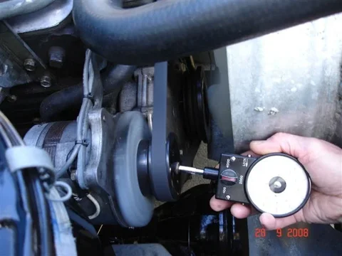
So prior to adjusting the tappets (adjusting the valve clearances) I measured the alternator RPM using my antique tool:

Injector01.webp

I got 1400 (cold) and 1510 (hot)

And this is what the gauge said when I judged the engine to be "hot":

WarmIdle.webp

Using the same formula I used to find cranking rpm, these figures equate to crankshaft figures of 792 RPM (cold) and 854 RPM (hot).

Now correcting the excessive tappet clearances has got to make the engine idle faster! Sure enough - Afterwards I measured the alternator RPM as 1420 (cold) and 1530 (hot). This equates to crankshaft speeds of 803 RPM (cold) and 865 RPM (hot).

Here's a section from the B-engine manual that says my idling RPM should be adjusted to between 625 and 675 RPM:

idlespeed.webp

Well actually - before correcting the high idle-speed I'll wait and see if fitting the reconditioned injectors raises it further. (I think it should raise it further if it provides more even spray patterns and more consistant open/closing pressures.)

Hey - Once I have done all this and got the idling RPM "within spec" I should find it easier to shift from neutral to 1st at the lights. (Not that it is particularly difficult to do that now - But I sometimes find it easier to shift to 2nd instead because 1st can need a harder push .)


But the main thing I've been up to today is creating a video of my cruiser being started with the old injectors in place. I'll add a link to that here as soon as I get it up and running on U-tube.

Link:
http://www.youtube.com/watch?v=jCmdF19KaEk


Hopefully this video will be useful for making comparisons once my reconditioned injectors (supplied by Engine Australia) are fitted.
Injector01.webp
idlespeed.webp
WarmIdle.webp
 
Last edited:
Another thing I did in preparation for comparing "performance" was to record my "best speeds" on certain sections of local roads.

Here is a main highway near here:

InjectorNgauranga.webp

The speed limit on this long steeply-climbing section of highway is 80 kph. Well "Tojo" (as my wife calls it) quite rapidly loses speed in top gear when I "start hittin that hill". And when I whack it down to 3rd she is hard-pressed to maintain 70 kph (but does). (Actually on one particular test day the cruiser did get back up to the 80 kph limit by the top of the hill - However I think I must have had a tail wind then:D)

(By the way - the cruiser was basically empty - except for me - and the winch was not fitted.)

And another hill closer to home has the cruiser "dying in 3rd gear at 40 kph" but "accelerating rapidly when I change down to 2nd". (In 2nd it goes up quickly to what feels like the "revv limit").

I'll be seeing if there is any change in these results with the new injectors (but I don't expect there to be much difference really).

It is very hilly round here because the land is shaped by earthquakes. (Apparently some people compare Wellington NZ to San Fransisco USA.- Oops - I'm sure I've spelt that city wrong)
InjectorNgauranga.webp
 
Another thing I did in preparation for comparing "performance" was to record my "best speeds" on certain sections of local roads.

Here is a main highway near here:

The speed limit on this long steeply-climbing section of highway is 80 kph. Well "Tojo" (as my wife calls it) quite rapidly loses speed in top gear when I "start hittin that hill". And when I whack it down to 3rd she is hard-pressed to maintain 70 kph (but does). (Actually on one particular test day the cruiser did get back up to the 80 kph limit by the top of the hill - However I think I must have had a tail wind then:D)

(By the way - the cruiser was basically empty - except for me - and the winch was not fitted.)

And another hill closer to home has the cruiser "dying in 3rd gear at 40 kph" but "accelerating rapidly when I change down to 2nd". (In 2nd it goes up quickly to what feels like the "revv limit").

I'll be seeing if there is any change in these results with the new injectors (but I don't expect there to be much difference really).

It is very hilly round here because the land is shaped by earthquakes. (Apparently some people compare Wellington NZ to San Fransisco USA.- Oops - I'm sure I've spelt that city wrong)

:eek::eek::eek: Be glad you didn't have a pyro during this playtime, or you probably would have shat yourself!!!
 
:eek::eek::eek: Be glad you didn't have a pyro during this playtime, or you probably would have shat yourself!!!

I've already decided I don't want one of those (or an aftermarket oil pressure gauge either). I definitely prefer to "drive in ignorance" of such things. :D
 
Well now........... I was delaying the injector work because I wanted to keep the cruiser ready to dash down to "the South Island" to do some work down there. - But for reasons I won't go into, that work can't be done this month anymore. so I fitted the reconditioned injectors today.

PS. In this country we are rather unimaginative with the names we use for the two islands that make up the vast bulk of our nation. We call these islands simply - "The North Island" and "The South Island". And why we keep doing so is beyond me - Particularly when it is very "PC" nowadays to return to Maori names. Why on earth don't we adopt Maori names for these stupidly-named islands?????

Anyway, ---- First thing this morning (well - 10am actually), I applied penetrating oil to the nuts I had to undo, had breakfast, then ran the engine a while to warm it up and let the penetrating oil do its thing:

InjectorWD40.webp

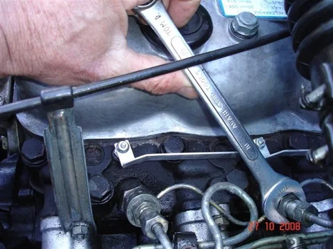
Then I undid the "high-pressure line-connections" to the injectors. (Well - I turned the engine off first. Ha ha.):

Injector17mm.webp

And removed the 2 bolts that secure these high pressure lines to the inlet manifold (via two "antivibration backets"):

Injector10mm.webp
InjectorWD40.webp
Injector17mm.webp
Injector10mm.webp
 
Last edited:
I removed only the two foremost high pressure lines because I found the other two were long enough to be able to be easily moved out of the way (without straining the pipes) when removing the old injectors and fitting the reconditioned ones.

Next I undid the nuts that secure the "leakage manifold" to the injectors. There are no sealing washers beneath these nuts because all the sealing is done on the other side (where aluminium sealing washers are used).

Injector19mm.webp

Here is the "leakage manifold" loose and ready to be lifted clear (but I found it easier to remove it when the 2 closest high-pressure fuel delivery lines were taken completely away):

InjectorManifold.webp

Note that I didn't bother disconnecting the "leakage manifold" from the "leakage pipe" (to which it is connected by means of a short section of small-bore flexible tubing and a couple of "tiny hose clamps" - that are very prone to leaking air into the fuel circuit) that runs down the block to the "fuel pump inlet".

Now the old injectors were VERY hard to break free! Here is my first unsuccessful attempt at undoing them using my largest torque wrench (on its highest setting):

InjectorUndo1.webp
Injector19mm.webp
InjectorManifold.webp
InjectorUndo1.webp
 
This second attempt was successful (using the operating handle from a Hilift Jack as an extension for more leverage):

InjectorUndo2.webp

Man! There was a lot of corrosion between the injector bodies and the head. (A mixture of "baked fishoilene" AND corrsion really.) Looking at No. 4 injector here, it looks like water went right down the thread to cause corrosion just above the "seat gasket"!

InjectorsOld.webp

This left me with a tricky clean-up job.

Here are both the old washers and a lot of cr#p inside one injector port/hole:

InjectorWashOld.webp
InjectorUndo2.webp
InjectorsOld.webp
InjectorWashOld.webp
 
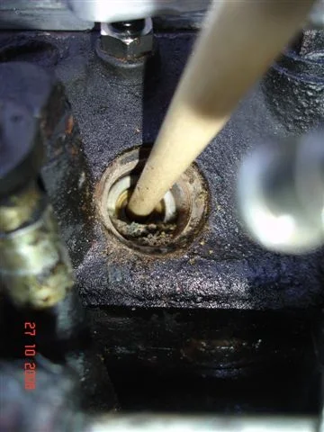
I stuck an old paint brush handle (rather a loose fit really) down the holes (where the nozzles poke) to try and stop most of the debris from falling into my "precombustion chambers":

InjectorBrush1.webp

And proceeded to scr#pe most of the cr#p away:

InjectorBrush2.webp

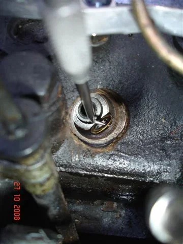
Here's me lifting out an old "nozzle seat washer":

InjectorWashOldA.webp
InjectorBrush1.webp
InjectorBrush2.webp
InjectorWashOldA.webp
 
And here's me lifting out an old "seat gasket washer":

InjectorWashOldB.webp

Note that this "seat gasket washer" is the only one of the three washers/gaskets that has a correct and incorrect orientation. It must be placed with the concave surface uppermost!

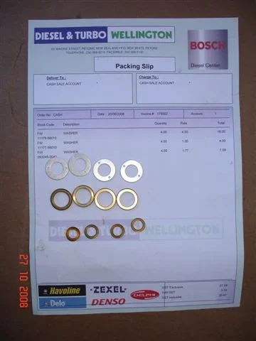
Here are the new washers I purchased from a local diesel shop:

InjectorWashers.webp

And here is a hole with the new washers in place (awaiting the insertion of a reconditioned injector):

InjectorWashNew.webp
InjectorWashOldB.webp
InjectorWashNew.webp
InjectorWashers.webp
 

Users who are viewing this thread

Back
Top Bottom