B engine compression & leakage testing along with glowplug & injector replacement

This site may earn a commission from merchant affiliate
links, including eBay, Amazon, Skimlinks, and others.

And here is the whole busbar reinstalled:
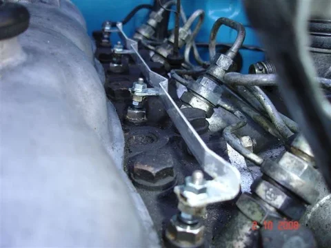
2 Oct 010.webp

Now for the performance of the new plugs:

First the ambient temperature for this latest test was 1/2 oC warmer than before (13 1/2 oC or 56 oF instead of 13 oC). And these were the results (with the former figures for the old ND plugs in brackets):

It took 13 sec (15 sec) till I could see some sign of glow in the glow controller and 25 sec (30 sec) before "full glow" was achieved.------- Slightly shorter I think - but that could just be my imagination because my judgement of "glow" is entirely "subjective".

Voltage at G: 10.9V (10.4)
Between G and S: 2.3V (2.4)
At S: 8.6V (8.4)
2 Oct 010.webp
 
Now for the interesting question (for me anyway)......

What current does my glow system actually draws off my battery?

And I definitely have around 8.5V available at my busbar - So if the FSM glow plug resistance figure of 0.2 ohms is correct - Each plug must then draw 42.5A giving a total glow current of of 170A - which is way too high IMO!!!!! (So I think the FSM resistance figure is wrong.)

By the way - I never trust my own resistance readings because a multimeter (like any of the ones I use) uses a very low "test voltage" and I believe the result can be greatly influence be the nature of the surface at the "pinpoint" where my probe touches etc. (Whereas I do trust my voltage readings - even though their values have been shown to vary. - In fact most were continuing to vary ....by as much as 0.01V per second .... as I took my final readings!)

So I decided to cautiously test it with one of my big meters that can measure up to 12A (not wishing to fry my meter).

Here's how I connected the meter into the glow circuit:

3 Oct 001.webp

And here is the meter itself:

3 Oct 002.webp

I got my son to turn the key backwards and then I "briefly touched" the "final connection" to make the glow current flow.

Result ---------


Yep - The meter wants to go "way past full scale".

And my estimate - based on the sound of the spark and on the needle's rate of acceleration across the dial - is that we have probably around 30 A here.
(I did this little test twice - Each time making sure the connection duration was minimal (insufficient to damage the meter).


:hhmm: I saw a little -30 to +30 automotive ammeter 4-sale in a junk bin outside my favorite antique shop yesterday - So if it is still there today I'll buy it and try testing the glow current again with that.

I'll keep ya posted in the next thrilling episode :D
3 Oct 001.webp
3 Oct 002.webp
 
Last edited:
I don't think either of us are shocked that the current was higher than 10A (:rolleyes:) but good to verify, thanks.

You should get that bigger meter, I wonder how much the current falls as the plugs heat up (resistance increases with temperature)... :D
 
Correct me if I'm wrong but the calculated current for a paralell circuit is the inverse of the total current draw, or 1/(1/10.2)+(1/10.2)+(1/10.2)+(1/10.2)= 10.63 amps?? I think thats the right formula
So I think the FSM is correct and if you were drawing 170 amps could most batteries keep up?, also if you consider the size of the glow plug and the voltage and the time it takes to heat up, it really can't draw much current?

Cheers

You're very right, except the resistance of the plugs is much less than 10.2 ohms. Tom said he found a value of 0.2 ohms (although I couldn't find this number in my FSM, and I know from attempts to measure my own that they are certainly <1 ohm.

A battery can certainly provide the 170A I speculated- the starter motor itself on most vehicles consumes >100A. A 3B starter is rated at 4.5kW (I think), which for a 12V truck is 375 amps (!!!!!).

The FSM I have been looking at is for B and 2B engines (not 3B).

And I thought our 12V gear-reduction starters (mine is common with your 3B Drew) are 2.5kW - but yet I have heard of 4.5kW starters . (I think the 4.5kW gear-reduction starters were 24V. Edit 4 Oct - Checked - Yes 4.5kW is 24V only) But anyway - Even 2.5kW is about 210A. (But the starter cabling is built to take that amount of current whereas the glowplug is nothing like the same size of course.)

And I seem to remember that "inverse formula" applies to resistance and not current.
In other words - 1/Rt = 1/R1+1/R2 + 1/R3 + 1/R4

So the inverse of "the overall resistance of the parallel combination" is equal to "the sum of the inverses of the individual resistances".

Anyway - it is will deep regret that I must advise everyone that "some other old scavenger" has beaten me to that old brittish-made ammeter in the antique shop's $1 junk bin. (I stood there rummaging through it for ages and eventually confirmed I'd been beaten to it by speaking with Lynne - the shop's co-owner.)

So we won't find out the true size of the glow current in the immediate future (unless someone else can do it on their cruiser). :frown:

I could try removing the ammeter from my old matchless motorbike - but I don't think it's worth the trouble. (I'll just keep an eye out for a cheap suitable DC ammeter and if I stumble across one - I'll repeat the test then.)

:cheers:
 
Last edited:
you got problems..
those readings suck.
340 is way too low...

but, lets carry on the read..

No1: 400psi - No2: 340psi - No3: 360psi - No4: 420psi
 
so stick it in gear, apply the emergency or get your wife/kid to hold the brake if that worried///
I'm not sure whether I'll even bother to proceed with it - Because of the difficulty in determining TDC (but as I say TDC probably doesn't matter and I should be able to stop the engine spinning - as a result of the applied air pressure - by locking the engine in gear) and because I'm happy with the engine's condition anyway (nothing really there worth finding out about).

We'll see!
 
the more i read this thread the more i am getting to like you...

IA workmate used to always refer to electricity as "elec-trickery" and this is why!

Calculations are often all theoretical nonsense IMO.

.
 
that system is the basic "wilson switch" glow system... pretty hard to have it act up...

BTW, if it is raining inside your garage (as stated in a earlier post) maybe you should read up on "roofing"...
Meanwhile I'm trying to finish gathering data relating to my glow system. Hopefully it will be useful to myself and others (who own diesels that use the same glowplugs) for "faultfinding" in the event of our glow systems developing faults. (At present my glow system operates perfectly!)
]
 
Okey Dokey! I'm all set to do the tappets and redo the compression testing ...... but that have to wait till the weekend (assuming the weather will be kind then).

Meanwhile I'm trying to finish gathering data relating to my glow system. Hopefully it will be useful to myself and others (who own diesels that use the same glowplugs) for "faultfinding" in the event of our glow systems developing faults. (At present my glow system operates perfectly!)

(I obviously had to get my glow system working again anyway in order to get my engine restarted so it could be "warm and well lubricated" for the tappet adjustments and next round of compression testing.)

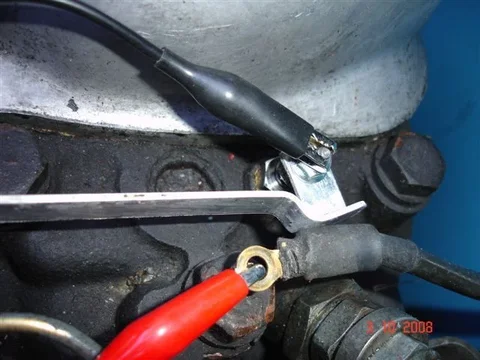
Here's a busbar connection:

View attachment 263997

And here it is after the busbar has been cleaned up:

View attachment 263998

And here is the whole busbar cleaned. (It is in perfect condition.):

View attachment 263999

Tom,
I don't mean to break your stride here but a quick question, what did you use to clean your bus bar, it looks good enough to eat with.:cheers:
John
 
.....BTW, if it is raining inside your garage (as stated in a earlier post) maybe you should read up on "roofing"...

The truth is that my cruiser can't actually fit in my garage Wayne. (It's small, full of motorbikes, tools, and junk. ) My 10-year plan involves enlarging it. (But my 10-year plan isn't set in concrete and could be postponed/abandonned. - Who knows? Or cares for that matter? I'm very "laid back" in my golden years!:D)
So the cruiser's garage has always been just the driveway outside. (It has never been garaged in its life!) And when I work on it is determined a lot by the weather. (Wind is just as annoying as rain.)

you got problems....those readings suck....340 is way too low....

But 340 is just 2 psi outside the "10% variation"! So I "rest easy" about it.
And anyway - I'm hoping that figure will be one that'll improve after I've redone the tappets.

:hhmm: Funny! I thought I had adjusted them at least twice in my cruiser's lifetime but looking at my records it looks like I did them only once and at a very early stage (2 yrs old and 41,000kms).

And I'll never bother stripping an engine down without there being an identifiable problem needing fixing (like difficult starting, rough idle, smoking, or excessive oil use).

But I'm still pleased to be doing the tests at this stage - even if it is just to have values to make comparisons with in the future.

:cheers:
 
Tom,
I don't mean to break your stride here but a quick question, what did you use to clean your bus bar, it looks good enough to eat with.:cheers:
John

Hi John

That varnish-like muck that was on it was "fishoilene" because I used to throw that stuff everywhere. (I'm more reluctant to do that now because I've realised it turns so dark in colour and looks so bad.) But it really does work well in preventing corrosion.

Anyway, I cleaned the busbar - and got rid of all the black paint under most of the fishoilene too - just using a pocket knife. Then I scrubbed it with a touthbrush and a product here called "Jiff" which is just a household cleaner used to clean smooth surfaces like those in baths, shower cubicles and sinks. (A white creamy liquid that feels like it is a "suspension of grinding-powder".)

I thought of using a proper industrial cleaner like the POR15 Marine Clean I have - but I have noticed it is very harsh on aluminium and I thought it might harm the electrical conductivity at the connection points by "excessively oxidising them" (which is what it seemed to do to the alloy on my freewheeling hubs when I used it there).

I don't really know what the busbar is made of. It looks to me like some sort of aluminium alloy. It is certainly much stronger/harder than your standard aluminium and I'm sure I've seen this stuff used alot in electrical contactors so it is probably fairly specific to the electrical industry.

I will repaint the busbar (excluding the connection points) when I'm finished the compression and leakage tests to make it look nice and resist corrosion too. (Just black POR15 and black rattle-can topcoat.)

:cheers:
I look forward to making my engine look snappy like that, very cool weekend projects. I'm still working through the big stuff though. Someday...
 
LOL!!
i love your attitude, it reminds me of me sometimes but to work on a cruiser when it is cold, raining and miserable... not for at least 2 decades ago..

compression: 420 - 10% is 42 so 380 is acceptable... 340 is WAY too low...
for that to be acceptable (and there is NO WAY that would be in my books) is if the highest was 375...

but, if you are happy then what difference does it make what the readings are...

in reality, unless you are ready to rebuild and the performance is acceptable to you, then drive it and enjoy it...
no offence inteded M8
cheers
The truth is that my cruiser can't actually fit in my garage Wayne. (It's small, full of motorbikes, tools, and junk. ) My 10-year plan involves enlarging it. (But my 10-year plan isn't set in concrete and could be postponed/abandonned. - Who knows? Or cares for that matter? I'm very "laid back" in my golden years!:D)
So the cruiser's garage has always been just the driveway outside. (It has never been garaged in its life!) And when I work on it is determined a lot by the weather. (Wind is just as annoying as rain.)


But 340 is just 2 psi outside the "10% variation"! So I "rest easy" about it.
And anyway - I'm hoping that figure will be one that'll improve after I've redone the tappets.

:hhmm: Funny! I thought I had adjusted them at least twice in my cruiser's lifetime but looking at my records it looks like I did them only once and at a very early stage (2 yrs old and 41,000kms).

And I'll never bother stripping an engine down without there being an identifiable problem needing fixing (like difficult starting, rough idle, smoking, or excessive oil use).

But I'm still pleased to be doing the tests at this stage - even if it is just to have values to make comparisons with in the future.

:cheers:
 
Yup, my calculations were way out to lunch on the total resistance, right formula, wrong number. The formula does work out to 170 amps, which can't be right! I searched through my various FSM's tonight and can't find any reference to 0.2 ohms for the glow plugs?? it just says check for continuity? also as pointed out earlier the resistance will change as they heat up. Tommorrow I will get a current reading from the main feed to the busbar with a clamp-on ammeter and see what flows to all four, I will also get a voltage reading at each plug for reference?
So if anybody could point me to the page number in the FSM that states 0.2 ohms please do.
If I can find a helper tommorow I will try and get pic's of the readings as the plugs heat up, and BTW mines a 24 volt system so the 12 volt numbers will be a little different.

Cheers
 
.....Tommorrow I will get a current reading from the main feed to the busbar with a clamp-on ammeter and see what flows to all four, I will also get a voltage reading at each plug for reference?......

Cool - Thanks Freebie

I've got a clamp-on ammeter but I've always assumed it wouldn't work on DC. (Maybe I should try it?)

...So if anybody could point me to the page number in the FSM that states 0.2 ohms please do.....

Page 8-4 and 10-25 of this manual:

Manual.webp

Note that I believe Toyota wrote this manual before releasing the 3B engine.


.....If I can find a helper tommorow I will try and get pic's of the readings as the plugs heat up, and BTW mines a 24 volt system so the 12 volt numbers will be a little different....Cheers

I look forward to seeing your results

:cheers:
Manual.webp
 
You need a DC ammeter, with a high current capacity which most clamp-on meters are? most small multimeters are limited to 10 amps max and fused, I did notice on one wiring diagram a 50 amp fuse in the glow circuit, so thats what I expect to find?? (mid 40's)
I'll keep you posted
 
You need a DC ammeter, with a high current capacity which most clamp-on meters are? most small multimeters are limited to 10 amps max and fused, I did notice on one wiring diagram a 50 amp fuse in the glow circuit, so thats what I expect to find?? (mid 40's)
I'll keep you posted

Dick Smith Electronics have a nice one, cost just under $NZ200. The same thing is sold by someone else in aussie for almost double the price.
Mine has been invaluable for sorting out starting issues and other high current measurement. Reads up to 1000A DC on coarse scale, 400A on fine scale. Highest I've found was 513 amps.
 

Users who are viewing this thread

Back
Top Bottom