
Navigation
Install the app
How to install the app on iOS
Follow along with the video below to see how to install our site as a web app on your home screen.
Note: This feature may not be available in some browsers.
More options
Style variation
You are using an out of date browser. It may not display this or other websites correctly.
You should upgrade or use an alternative browser.
You should upgrade or use an alternative browser.
Adding F/R lockers to 2003 Land Cruiser
- Thread starter sdnative
- Start date
This site may earn a commission from merchant affiliate
links, including eBay, Amazon, Skimlinks, and others.
From 2000 on has ATRAC so they have separate brake circuits.
@sdnative should of hit me up, I will/would gladly give you a hand. I'm good at drinking beer, handing tools and parts out lol
- Thread starter
- #45
Got the new gasket installed and the third buttoned up. I tested the locker actuator to make sure the fork cleared the notch in the housing as it unlocked. When unlocked, the fork sticks out less than the other part of the carrier so no contact. If the third fits into the housing, then the fork will not make contact as it unlocks if that makes sense.

The stud part numbers are as follows. Studs are 10mm x 1.25. Starting at the top and going clockwise lengths are:
63.5mm (P/N 90116-10167)
53.5mm (P/N 90116-A0025)
40.5mm (P/N 90116-10074)
40.5mm
53.5mm
53.5mm
40.5mm
91.4mm (P/N 90116-10124)
91.4mm
40.5mm
Six of these are the same size as the later model, so really only four studs need to be changed (I'll let you figure out which)
Washers are P/N 90201-A0004 (need 10)
Nuts are P/N 90170-10021 (need 10)
Locker third member to housing gasket P/N 42181-60070
Last edited:
- Thread starter
- #46
What's the best way to clean up the axle flange mounting surface?
Factory was metal on metal. Should I put something there? I saw in this thread by @Skidoo that he used anti sieze. I understand that this can dry out and crumble. Any suggestions?
Rear axle bearings pics


Factory was metal on metal. Should I put something there? I saw in this thread by @Skidoo that he used anti sieze. I understand that this can dry out and crumble. Any suggestions?
Rear axle bearings pics
Last edited:

What about the o-ring? Does it just go over the outer housing like this?
Yes on o-ring install. Because of the rust I decided on anti-seize, but maybe you could come up with something better.
Needs to be waterproof and stand up to some heat from brakes.
- Thread starter
- #49
Yes on o-ring install. Because of the rust I decided on anti-seize, but maybe you could come up with something better.
Needs to be waterproof and stand up to some heat from brakes.
Thanks. I used a very light film of wheel bearing grease (link below) on the flange. Bad idea? Now I'm worried about the grease attacking the rubber o-ring. It's all buttoned up and full of gear oil. I'd hate to pull it apart again.
Valvoline™ Multi-Purpose Grease/GM : Product Catalog - Valvoline™
Think that o-ring would be fine with that grease.
- Thread starter
- #51
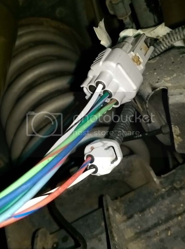
Can someone with a 98/99 locked truck snap a picture of where the locker harness enters the body? There should be two plugs on the harness, the one on left containing locker motor/switch wiring (6 pins) and the one on right containing ABS sensor wiring (4 pins). I am trying to determine the best way to route the new harness.

Nice, work! I was wondering if you were going to keep it, looks likes it's here to stay... at least for a little while longer.
- Thread starter
- #53
Nice, work! I was wondering if you were going to keep it, looks likes it's here to stay... at least for a little while longer.
Yes I am going to keep it for another few years then probably move to a 200. I am having second thoughts however if I want to put a locker in the front. I may just replace the R&P and call it good.
- Thread starter
- #54
Built the new harness. I still have to wrap it and route properly, but this allow me to test. Seems to work great. Locker actuates properly and the light blinks when the locker is not engaged, and goes solid when it engages.

- Thread starter
- #55
The connectors that plug into the diff are part numbers 90980-11156 and 90980-11194. The connector that plugs into the Diff Lock ECU is 90980-10801. The connector that plugs into the dash switch is 90980-10631 (same for the 100-series and 80-series).
I used these terminals for the sealed connectors:
Home » Shop » Connectors / Harnesses » Sumitomo » Sumitomo TS / SL Female Terminal 0.5 - 1.25 mm2 ( 20 - 16 AWG )
(Sumitomo TS / SL Female Terminal 0.5 - 1.25 mm2 ( 20 - 16 AWG ) Part # CONN-11856
and these for the unsealed:
Home » Shop » Connectors / Harnesses » Sumitomo » Sumitomo TS / SL / DL 090 Unsealed Female Terminal 0.5 - 1.25 mm2 ( 20 - 16 AWG )
Sumitomo TS / SL / DL 090 Unsealed Female Terminal 0.5 - 1.25 mm2 ( 20 - 16 AWG ) Part # CONN-100800
and these seals. They seem to work fine, but I am not sure they are the exact replacement
Home » Shop » Connectors / Harnesses » Sumitomo » Sumitomo HM / MT / TS Sealed Series wire seal, black ( 20 - 16 gauge )
Sumitomo HM / MT / TS Sealed Series wire seal, black ( 20 - 16 gauge ) Part # CONN-00145
This is the crimper I used:
Hozan P-707
The place for all your motorcycle electric needs.
^ they are overseas, but I was also able to find it on amazon
I used the 2.0 or 2.4 die on the wire crimps and the 3.5 die on the insulation/seal crimp.
I used 16ga GXL wire for everything. I tried to use the proper colors (more or less) according to the EWD.
Last edited:
- Thread starter
- #56
The Diff Lock ECU has an IC chip (circled in red) and I am not sure what it does internally. It has two safeties, one to make sure the XFER case is in 4LO (pin 8 labeled 4WD), and another to prevent the locker from engaging above 5mph (pin 10 labeled SPD). The 4WD safety seems to only require 12V to defeat. The SPD safety is a PWM signal from the combination meter. I am not sure if simply applying 12V or GND will defeat this one. I left the pin disconnected and it seems to work properly so.... Anybody know what it needs?

- Thread starter
- #58
On to the front...
After thinking about it some more, I am finding it hard to justify the cost of the front locker. I will most likely just replace the gears at this point. Already have an appt with Zuk.
Took the diff out today. It was actually much easier than I had anticipated. Maybe 4-5 hours in my garage with common tools to get everything apart. Here is the third, looks like 8 teeth on the ring gear are broken.
- Thread starter
- #59
Is it possible to identify if the carrier is 2 pinion or 4 pinion while assembled? I know the 2003 uses 4 pinion, but the PO had the diff replaced and I want to make sure they put a 4 pinion back in there. The receipt shows P/N 41110-60801 which would be correct, but just want to be sure.
Looks like a 4 pinion to me - iirc the 2 pinion carrier has a much more open design / less material. Also you can count the pinion shafts in the sides of the carrier and they also look like you have 4.