
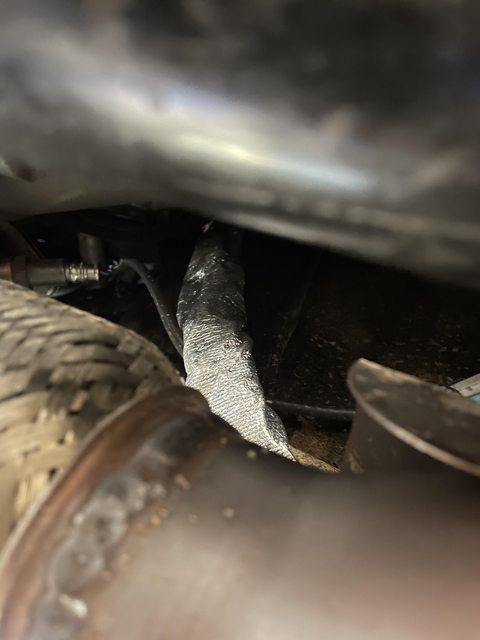
Definitely run braided AN line and wrap it in a heat shield and youll never have to worry about it. DEI makes really good heat wrap to reflect radiant heat, and if you are running cats, they make a heat shield that you mount to the cat itself to bounce some of the direct heat out of there. I use the nylon braided lines because i like all of my stuff to be black, they make stainless braided lines too.
If you dont want to redo your lines you can just use the DEI heat shield that has a velcro enclosure and secure it with stainless zip ties too.
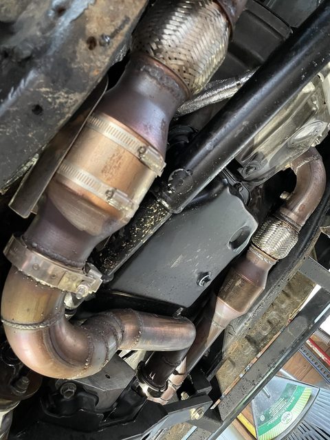
heres the heat shield for the cat
DEI Heat wrap
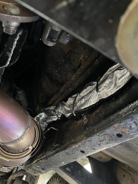
If you dont want to redo your lines you can just use the DEI heat shield that has a velcro enclosure and secure it with stainless zip ties too.
heres the heat shield for the cat
DEI Heat wrap
