Upgrading stock alternator to 130/150 amp

This site may earn a commission from merchant affiliate
links, including eBay, Amazon, Skimlinks, and others.

Can someone help me out here. Doing this upgrade and trying to clean up my wiring some. I realize I am trying to reinvent the wheel here, but I am hoping someone can help me out. Part of this is so I do not have to cut up my OEM harness, if possible.

Using this Terminal Block I was hoping to clean up the battery posts.

I have attached a wiring diagram of what I did. My problem is the alternator is not charging. The alternator is a store bought Reman'd Denso part# 210-0538.
 

Attachments

Last edited:
Can someone help me out here. Doing this upgrade and trying to clean up my wiring some. I realize I am trying to reinvent the wheel here, but I am hoping someone can help me out. Part of this is so I do not have to cut up my OEM harness, if possible.

Using this Terminal Block I was hoping to clean up the battery posts.

I have attached a wiring diagram of what I did. My problem is the alternator is not charging. The alternator is a store bought Reman'd Denso part# 210-0538.

I would start with how you rewired the alternator plug. Double check you have the wires in the correct position....

https://forum.ih8mud.com/attachment.php?attachmentid=604690&stc=1&d=1330359435
 
I would start with how you rewired the alternator plug. Double check you have the wires in the correct position....

https://forum.ih8mud.com/attachment.php?attachmentid=604690&stc=1&d=1330359435


I triple checked that. That was actually my first thought. Maybe my ECU was not telling the alternator to charge. I will check again but I am confident it is correct.

I suppose I could have buggered up one of the pins. I had a hard time getting the first one out, before I realized I needed to pull that white tab out first. Looks like Toyota has a pigtail available. So I may go that route.

EDIT: I have been emailing with Bill (photoman), and his first response was the connector pins also. But I did want to clarify that where I have the AM1 fusible link in my drawing that is the factory fusible link ring connector. Where it normally connects to the battery I connected it to the terminal block that runs directly to the battery. I did not disconnect anything inside the black AM1 box.
 
Last edited:
Mod5csi, time to go back to basic. Have the alternator tested. If you can, take the wiring back to stock format (I am not the expert, but I don't think your new wiring design could have caused this issue)

GL
Stu
 
Check continuity from the alt back to the battery first, put it right in the heavy cable side pin on the alt connector and straight to the pos term on the bat. If you don't have cont there then step it one at a time
Alt to fuse
alt to opposite side of fuse
Alt to term block and so on.

Also if you didn't get those terminals snapped in the connector correctly they will back out enough that there won't be a connection, it may look fine before you plug it in but push on each one on the mating side to see if you have them locked in the connector housing
 
Ok all. Thank you for your input.

I checked continuity everywhere. And I when I checked voltages I had battery voltage at every connection.

Working with Bill I changed my wiring some but that was not my problem, even if it was wonky.

We were all on the right track originally. It is my pigtail not making a solid connection at the alternator.

I tried wiggling the connection while it was running and it started charging. It vibrates loose after just a couple seconds.

I'm going to try and get a new connector and pigtail so I have both on hand.
 
Ok, hoping someone can clarify the wiring. I read and read this thread but am still completely unsure of exactly what I should do. I want to make the wiring as clean as possible. Please tell me if the below is correct based on the pics.

Pic 1, large wire with dots on it and smaller wire that go to B + post on Alt., Larger wire is cut and shrink wrapped, taped up with electrical tape back to harness. Then the smaller wire is connected ALONG with the new larger 4 guage wire and connected to the alt post, the 4 guage wire goes to the batt with a 150 amp fuse in between. with 150 amp fuse between alt b post and batt +, smaller white goes into the harness it's it's oem configuration.

pic 2, black box, am1 box, 3 wires here, 2 in the box and one with a connector, fusible link wire is cut (blue) and removed and tied into harness with tape, other 2 wires (one with connector and black wire) are connected to a 10 guage wire and sent to batt +.

Trying to get this done asap, appreciate the help.

Noah
photo.JPG
photo (1).JPG
 
Just put the original wire terminal back on "B" at the alternator (I.E. both white wires) along with the new 4 gauge wire. Then just unbolt the blue fusible link in the AM1 box and tape its ring terminal end. Done.

Edit to add another perhaps easier way to do the wiring . Post #128 in this thread.
 
Last edited:
Just put the original wire terminal back on "B" at the alternator (I.E. both white wires) along with the new 4 gauge wire. Then just unbolt the blue fusible link in the AM1 box and tape its ring terminal end. Done.

ok thx Bill, the AM1 box goes to the + on the battery, correct?
 
ok thx Bill, the AM1 box goes to the + on the battery, correct?

Yes, through the fusible links. The new 4 gauge wire you said you had will go from the alternator "B" post to a new 150 amp fuse holder, then from the new fuse holder to battery positive (a new larger charging wire). The old stock charging wire will be reconnected at the alternator "B" so the other wire that is crimped in the stock wire terminal will still have power to feed some circuits in the under hood and under dash fuse boxes. By unbolting or disconnecting the blue fusible link at the AM1 box the old charge circuit/wire is now open and will not charge. The blue fusible link wire ring terminal end that was in the AM1 box should be taped since the other end that is part of the fusible link bundle will be reconnected to battery positive and be hot. A sort of advantage to doing the install this way is if there is a circumstance where the 150 amp fuse blows and the cause is fixed but you don't have a spare fuse, the old fusible link can be reconnected in the AM1 box and could get you home.

Bill
 
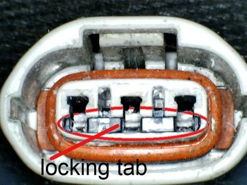
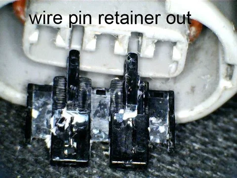
Here are a few pictures of how to remove the old wires from the stock alternator connector.
There is a locking or retaining tab in the connector that I just pry out with a small screwdriver by putting the screwdriver in one of the slots shown in the picture. Once the locking tab is popped out the wires are just pulled or pushed out through the back of the connector.


Stock-80-amp-connector-text.jpg Stock-80-amp-connector-insert-screwdriver-text.jpg Stock-80-amp-connector-insert-retainer-removed-text.jpg
 
Yes, through the fusible links. The new 4 gauge wire you said you had will go from the alternator "B" post to a new 150 amp fuse holder, then from the new fuse holder to battery positive (a new larger charging wire). The old stock charging wire will be reconnected at the alternator "B" so the other wire that is crimped in the stock wire terminal will still have power to feed some circuits in the under hood and under dash fuse boxes. By unbolting or disconnecting the blue fusible link at the AM1 box the old charge circuit/wire is now open and will not charge. The blue fusible link wire ring terminal end that was in the AM1 box should be taped since the other end that is part of the fusible link bundle will be reconnected to battery positive and be hot. A sort of advantage to doing the install this way is if there is a circumstance where the 150 amp fuse blows and the cause is fixed but you don't have a spare fuse, the old fusible link can be reconnected in the AM1 box and could get you home.

Bill


good point on the option to reconnect the fusible link, seems like a great idea to do it this way, thx bill
 
Have had the 150A alternator (reman from CDan) installed for a couple of days. When I first started the truck and then randomly, the red alternator trouble light will come on, and the voltage indication on the dash meter and on the ScanGauge will show wildly varying voltages from 13.8 to 17.2V. Then it will settle down for a while at 13.6 -13.8V with the red light randomly turning on and off.
It will put out the amps, I load tested it with the high beam and fan on high test, with the engine off until the battery voltage dropped to 12.05V and then started and ran up to to 1500 – 2000 RPM and it kicked out over 100A.
Am troubleshooting using a Fluke 12 multimeter and Fluke 337 clamp meter. The amps drop to 3.5 – 5A when the voltage is going wild. During all this it is keeping the three year old Platinum Diehard charged. I installed using all the original wiring (gathering cables & fuse needed for upgrade). This is not my DD, not urgent but it is frustrating. Have checked connections, checked for voltage drop from the alternator to the block as posted above, the FSM says to troubleshoot the ‘Discharge Circuit’ but that is all it says – no reference. There have been no electrical problems with the truck until the upgrade, and corrosion is not an issue. Read this entire post and searched, did not see any problems such as this.
 
what voltage is it putting out at idle and at 2000 rpm? sounds like maybe the internal voltage reg is bad on the alt? that would cause some problems (ask me how I know) as it would be pumping too much to the car and your fusible link will blow eventually.....
The voltage is all over the place (14 - 17V) when it is being wild at idle or any other RPM. I am leaning toward the internal VR also, but that seems unlikely on a Toyota reman?
 
I agree, seems unlikely but I believe it should be putting out a constant voltage, 17v is too much I believe, normally when I have tested working alt's they put out about 14, I would get it tested, hopefully someone smarter than me will post up, I had a rebuilt alternator where the vr died on it and it was putting out way too much, I have been told if it puts out more than 14v then the VR is not working correctly.
 
A few things to check. The "S" wire (black) at the alternator should have 12 volts power at all times. The "ig" (black with blue trace) should have 12 volts power with key on. Hopefully the pins from these wires are making contact when plugged in to the alternator. Up at the AM1 jump the black fusible link from the bolt to battery positive. This is from the "S" sense wire. If the black "S" fusible link is making intermittent contact it could cause voltage fluctuations. Could try to jump the other fusible link too. Since this is still running through the stock wiring the fusible links could have gotten partially broken when doing the install. An alternator going to 17 volts is almost full field which makes the voltage regulator suspect.
 
Thanks for your responses. Here are the results of the checks:
Battery 12.47V (key on)
'S' 12.44V all the time
'IG' 12.32V key on
'L' 12V key on

Measured the fusible links:
Old: New:
BU .1Ω .3Ω
BK .2Ω .3Ω
WH .5Ω .4Ω

Since I had the new fusible links, installed them to eliminate that factor.
Pulled and inspected the two white wires on the 'B' terminal - good crimp - good condition.
Obviously pulled the connector on the alternator to get above readings and had a close look at the 'pins' - look good. Worth noting that I was quite careful in the removal of the pins from the original connector (using the three pics in this thread for proper removal - very helpful) no bending, gouging, etc. I likely would not have removed them correctly without the pics.
Got everything back together, started the truck and the red trouble light was on, ScanGauge showing 13.7V (steady), 14V at the battery posts, amps on white wire from 'B' terminal about 5 -6A. Of course now that I understand the second white wire is feeding most of the vehicle, the clamp ammeter could just be reading the current from the battery to the second white wire feeds. It still isn't happy! Out of time for tonight.
 
One last thing would be to run a jumper from the alternator body to the engine block. The alternator needs a ground to work but I don't think this is the problem. It seems like a bum alternator. Unless someone else can come up with something I would say you will have to pull the alternator and take it to an alternator shop to have it tested.
 
One last thing would be to run a jumper from the alternator body to the engine block. The alternator needs a ground to work but I don't think this is the problem. It seems like a bum alternator. Unless someone else can come up with something I would say you will have to pull the alternator and take it to an alternator shop to have it tested.
Tested for a voltage drop when I read the post about a voltage drop someone had from alternator to block, and then clipped on a jumper from the alternator to block a couple of days ago - no drop, no change. Am going to take the vehicle to the local Auto, Battery, Electric (ABE) shop for a professional evaluation, they are super busy (good reputation), so it is taking a while to get in. Like most electrical problems, probably a poor connection, but I haven't been able to locate it.
 

Users who are viewing this thread

Back
Top Bottom