Ram Jet 350 to H55 install-73 FJ40 (2 Viewers)

This site may earn a commission from merchant affiliate
links, including eBay, Amazon, Skimlinks, and others.

DomSmith

SILVER Star
Joined
Nov 16, 2004
Threads
299
Messages
3,763
Location
Oceanside, CA (Fire Mountain)
Ram Jet 350 (and Serp Kit) to H55 Install-73 FJ40

Well, I figured I should start this thread up or else I'll never do it. Some of you may have seen my recent H55 swap thread and this came right on it's heels. I know, I should have done it all at once, but the idea of spending that much money in one pop was a bit frightening, besides, I figured I'd use the good motor I had in it for a year or two before considering another big project. Wrong. After a few months with the 5 speed I wanted a bit more drivability than my older Pro-Jection FI SBC was providing. (Yeah, that's the excuse).

Anyway, my rig is a 73 FJ40 that I've had for 13 years and after driving it for a LONG time with a 3 speed and a 350 I decided on some upgrades. So the H55 and now this Ram Jet 350...

I had spoken with Jim (centerlineseal) a few times and he was planning on a Ram Jet install on his 40 which got me thinking I needed a newer more reliable fuel injection than the simple Pro-Jection 2D that was acting up a bit. So after chatting with him, a few local cruiser tech gurus and getting a motor at dealer cost (not much less than the online clearinghouses) through a buddy at Toyota I took the plunge....

I ordered the Ram Jet 350 (GM PART# 12499120) and Serpentine Kit without air (GM PART#12497697)

ADDED: Here is a link to a page with some good Ramjet 350 info from Gilbert Chevrolet. There are 2 pages:

Gilbert Chevrolet Main Ramjet Page

Gilbert Chevrolet Second Page

I had a few small reservations when deciding on this motor. First, I didn't like the limited tunability of the Pro-Jection, and after talking with some Engine Gurus that's one knock on the Ram Jet. The stock ECM is password protected and is not tunable, you get a set tune and that's it. If you want to make adjustments you have to erase what you have and start from scratch. There are a few options out there (MEFIburn and some others) but nothing seemed that great and with my VERY limited knowledge on the subject I figured I'd just suck it up and stick with the stock settings. From speaking to a few people with Ram Jets in cruisers there didn't seem to be too many complaints. Now MSD has a kit w/ ECM, software, etc that lets you take back the tunability of the Ram Jet but those are a bit pricey to add on after already spending considerable $$$.

So for now it's the stock 350HP Ram Jet 350...
ramjet01.jpg
serpkit.jpg
 
Last edited:
The first step was to pull the other motor (originally out of an 87 van per PO) that I had added the Holley Pro-Jection many years earlier...

I started by taking tons of digital photos for reference if I ran into problems remembering where things went. I also unhooked the wiring harness from the motor and wrote where every wire went with blue tape and attached them to the wires to make it easy for my buddy to hook it up once he had time to drop it in his 40. Drained all the fluids,removed the radiator, etc...

At first I tried raising it up over the front but after failing (I had lost a lot of oil from the loaner cherry picker which prevented it from raising high enough) I conceeded and removed the bib. I barely squeezed the motor between the fender and the winch with literally an inch to spare...
enginepull3.jpg
enginepull1.jpg
enginepull2.jpg
 
Initially I had decided to drop the tranny and transfer case and had disconnected the driveshafts, drained all the fluids, removed the exhaust... but after reconsidering I figured I'd try just pulling the motor and leaving the tranny/tcase in. This worked quite easily on the way out, but now I was worried about getting it back in. I was doing this project w/o an extra set of hands so I was a bit stressed... but I figured I would worry about it when I got to that spot.

You can see here that I installed the 5 speed as high up as I could without making changes to the tranny hump. Not a lot of clearance between the two. It was nice to see the H55 install from this angle because I felt like it was going to hold up for the long haul.
enginepull5.jpg
enginepull4.jpg
enginepull6.jpg
 
After the motor was out I decided to get started on installing the serpentine kit onto the front of the Ram Jet. I read the (weak) instructions included with the kit from GM and sorted all the parts. The directions did not match the parts very well and the one diagram was a small bad photocopy that was almost no help at all. This was my first reality check. Maybe this wasn't going to be an easy swap of blocks... :confused: Without much confidence on this part I put it aside for later and decided to fit the rams horn manifolds to the Vortec heads.

At first they looked like a perfect fit but after putting them on and starting to snug them down I noticed they were hitting the valve covers. With a bit more tightening the covers were bowing a little and there was no way they would bolt down and make a good seal. I weighed the options and decided I would do a bit of two things. 1. The small bows in the valve covers were acceptable to me but I didn't want to do anymore for fear of springing a leak so I stopped there. 2. I decided to grind some off the manifolds and see if that would make up the difference. I assured that the area that needed to be adjusted was sufficient in thickness and then slowly took off material. I went back and forth fitting them about 10 times each until they fit correctly. I wasn't super stoked on the idea as they were coated manifolds, but I figured it was the only thing to do and I hoped they would still stay nice even with some of the coating gone. I did paint the small areas with some hi-temp paint but I don't suspect that will last long. Luckily it's on the back side and won't be seen.
manifold-fit.jpg
manifoldfit2.jpg
manifold-3.jpg
 
Next I disasembled the bellhousing and clutch on the old motor and prepped the new flywheel on the Ram Jet with a new pilot bushing. I then installed the clutch and bellhousing. I re-used the same clutch components and Downey 4 speed to SBC bell housing from the H55 swap that had maybe 1000 miles on them.
clutchpilot1.jpg
clutchcover.jpg
bellhousing1.jpg
 
After the clutch was in I reviewed the serpentine kit instructions again and contemplated installing it all before dropping in the motor. The directions were still a bit confusing and I decided not having the alternator, water pump, etc. would give me some wiggle room while installing the block. I was, after all, going to try to line it all up with the tranny without the help of anyone else. This is when the fun would begin...


First I had to line up the tranny with the bell housing, and since the clutch fork wouldn't stay on the bellhousing I had to install it once I got the input shaft lined up perfectly with the motor. This went much smoother than I thought it would...
install1.jpg
 
I had to grind my manifolds to work with those covers also. Mines a 330hp around a '98 block or so. They must make the later blocks a little different, my old pre '87 block had a lot more meat above the exhaust ports, and the manifolds never got close to the covers. I was worried that being that close to the covers they would burn the oil splashing inside the covers, but after 4 years they are good.
 
I'm not sure what I did to deserve it, but the motor lined up after only 6 or 7 small adjutsments at the tranny jack and cherry picker. I couldn't believe it! I was prepared for a long night of cursing and drinking to get this thing in and in less than 10 minutes of adjusting it was bolted in place.

On to the Serpentine Kit...
I tossed around the idea of putting this in a seperate thread so there would be a good Serpentine Kit write-up on it's own (I couldn't find one here) but decided just to add it to the Thread Title and stick it in.

I decided on the kit w/o air because I had hoped to use the York compressor from the On Board Air I had installed on the previous motor. Everything was going to have to be moved to the passenger side as the serpentine kit air bracket was opposite from my old 350 and I would need a new pulley and mount (we'll get to that later). The alternator was now on the drivers side also which would mean re-routing the wiring.

The kit comes with all the items seen here including a 15 page instruction sheet that is marginal at best. Some of the stuff is clear but there are several part #'s that didn't match and the diagram (photo) is nearly useless... I double checked that each item did indeed come with the kit and the confusion was mostly based on the fasteners as the #'s were wacked and the descriptions were bad too. One nice item that Poser brought to my attention was that all the parts go together and they have a GM and AC Delco part#. I had gotten used to beating my head against the wall trying to source parts that the previous owner had scabbed together each time something broke so this was going to be a nice clean kit. :) The kit comes with a remanufactured CS130 alternator (105 amp) and a reverse flow long style water pump. I had initially thought I needed a short pump for clearance but after measuring my pump I indeed already had a long.

The first part of the serpentine kit install was removing the normal rotation water pump that came on the motor and then mounting the AC Compressor bracket. It's held on with one stud (wrong part #) and then a nut near the top of the cylinder head (behind the bracket) and then with 2 bolts near the bottom of the bracket. Some of the bolts are Torx heads but luckily I had a set lying around. There was a second stud mentioned (wrong part # again) but I never could figure out what the hell they were talking about and the directions say it is not needed. :confused: These are the three studs in question... You can also see the idler pulley (which was the next step) installed near the top left.
serpkit.jpg
serpkit01.jpg
studs.jpg
 
Last edited:
The idler pulley is held on by two bolts and one stud (I believe the longest one). There was no good spot to grab the stud to screw it in (red arrow) so I just took two nuts, threaded them on the end of the stud and tightened them against each other. Then I used the outside nut to tighten the stud into the threaded hole. This is where the York would go but I wanted to be sure I got it all together and then I would add the OBA. There is also a brace at the back of the idler pulley that bolts to the stud and to the manifold but again the instructions were pretty weak. I had to post up here for some help (Thanks my64fj40): https://forum.ih8mud.com/showthread.php?t=184156. (The third pic is of the bracket provided by my64fj40). I had to add a nut on the bracket between the pulley and the brace for it to line up correctly and then snugged it down with a second nut on the stud. EDIT: See post #16, as I had to cut down the length of the stud).

After the idler pulley and brace were in it was time to add the belt tensioner and lower idler pulley. There is one bolt on the tensioner and 2 bolts holding the lower idler pulley from the front.
serpidlerpulley.jpg
serploweridler.jpg
P1010003-MUD.jpg
 
Last edited:
The next step is adding the reverse flow water pump (be sure to use the gaskets provided) with the four bolts and then you can add the pulley using the other 4 bolts. I decided to wait on adding the pulley until the end. EDIT: If you are going to run a 90 degree elbow off the front of the intake manifold for a heater hose you may need to install it before the water pump. I decided to add this after the fact and had to remove the water pump to thread it in.

Next I removed the bolt and washer holding the balancer in place and installed the crankshaft pulley re-using the removed bolt and washer. Be sure to line up the 3 bolt holes before tightening the main balancer bolt.

This is a good time to take a quick look to make sure all the pulleys are lined up.


Now it was time to add the power steering pump and bracket. There are five bolts that hold it in place, 2 that go in the block and 3 in the head.
serpwaterpump.jpg
serpcrankpulley.jpg
serppowersteer.jpg
 
Last edited:
After the power steering/alternator bracket was installed I attached the alternator with the upper and lower bolts. There is also another bracket on this side behind the alternator which attaches to the manifold. Again there were no diagrams in the instructions so you are left to best guess the location.

EDIT: I forgot to mention that the long stud behind the AC bracket was a bit too long for my liking so I cut it down a bit (pic 3)...
serpaltern.jpg
serpaltern2.jpg
serpstud01.jpg
 
Last edited:
Once the alternator was installed I hooked up the two power steering hoses to be sure what I had would work (these pics are obviously both ends of the low pressure hose). If I remember correctly the fittings I had (and what came in the kit) are both metric which was a lucky break. Both hoses fit well and I was able to move on to the next step after filling up the power steering pump with fluid.

Since I'm near the end of the Serpentine section I'll cover wiring the CS130 alternator even though this was actually done after the Ram Jet wiring was complete.

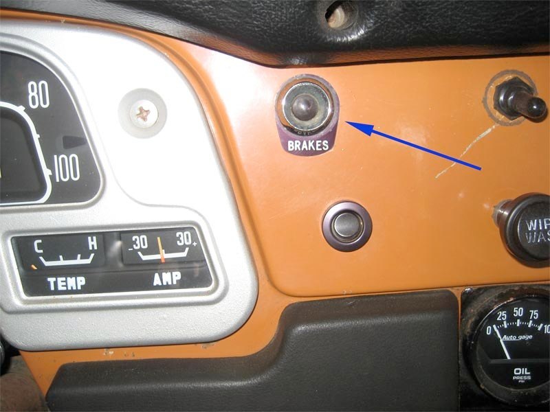
I searched and searched and looked at the Tech Article (CS-130 Alternator Wiring - Land Cruiser Tech from IH8MUD.com) on the wiring but could not for the life of me figure out what I was supposed to do with regards to the charge light. Looking back on it there's no doubt it's quite simple but I just wasn't confident on how I was doing it. I understood that I just needed a "charge" light or a resistor and I decided to try the light. At first I had a temporary light plugged in to a 12v source and then connected it to the alternator in the engine compartment but the light was on all the time that the key was switched so I know that wasn't right. What I finally did was tap into the ignition wire (black w/ yellow?) behind the dash and ran that wire to one of the wires coming from the stock red "brake" idiot light in the dash that had been disconnected since my disc conversion. I then ran the second wire from the back of that dash light to the "L" wire on the CS130. This worked well and the light is on when I place the key in the "ON" position and then goes out once I start the motor. The other wiring is quite simple and the Serp Kit comes with the pigtail needed.

4WD-indicator.jpg


I jumped from "S" (marked on the alt and wiring) to the "+" post on the alternator and then ran 4g wire directly to my main battery through a fuse. Then I connected the "L" wire to the dash "Brake" light as described above. The other two wires can be removed but I just soldered and shrink wrapped female butt ends on to protect them.

I decided to abandon the old wiring of the si alternator the PO did and capped them off. I know the large white w/ blue goes to the amp meter and I'm sure one was a battery wire but they are so wrapped up in the harness I figured I would let them be. As for now I'm running a Volt Gauge but do need to figure out what to do with the wires going to the Amp Gauge. It still reads negative all the time (since the charging side is out of the circuit) and I may leave it that way to keep an idea of how much juice I'm using. I know the 30 amp gauge would take a beating if I hooked it up now. I'm hoping someone has an idea whether it's bad to leave it all hooked up or not. Personal preference, but I HATE having gauges that don't work in the dash. I'll try to get that figured out soon.

I've since had the system checked at an electrical shop to be sure I didn't screw anything up.
serpsteerhose1.jpg
serpsteerhose02.jpg
serpaltwiring.jpg
 
Last edited:
I finished up by adding the water pump pulley and heater hose barb at the top of the water pump. My other heater hose connects in a T fitting at the lower radiator hose. I am having a few problems generating heat at the heater at idle so I think the lower T fitting may be my problem there. EDIT: See the note on using a 90 degree fitting at the front of the manifold in post #15 and #85.

After putting the radiator and Taurus fan back in I used the bad photocopied photo provided in the GM instructions to route the serpentine belt and used a ratchet to get it on. The tensioner is self adjusting which is a HUGE improvement over my old V-Belt setup. With a bunch of mis-matched parts from the PO and pulleys that lined up "pretty well" the tensioning was hell. This is a snap and there are instructions on how to read whether the serp belt needs replacing in the documentation. The pulleys sit no farther forward than my old V-Belt setup which I was worried about because of my limited (1") space from water pump pulley to fan.

That pretty much covers the serpentine setup. I did add the York compressor a week or so later and decided to give it it's own thread here: OBA For Serpentine Belt Setup.
serpheaterhose.jpg
serptension.jpg
 
Last edited:

Users who are viewing this thread

Back
Top Bottom