My Blue Beast, which is no longer blue

This site may earn a commission from merchant affiliate
links, including eBay, Amazon, Skimlinks, and others.

@bj40green, I have a full copy of all three pages of that diagram on my computer at work. I'll try to post them on Tuesday.
Please send copies to my email: ruud.coco@gmail.com

I will need to disconnect the headlight switch from the harness and then place my red probe in the pin connected to by the G-Y/G wires and the black probe into the pin connected to by the G-R wire, is that correct? Since this is for the headlights, the key will not need to be in the ignition, just need to make sure that the battery is connected.
Is that about right?
No. Remove switch from the dash and leave it connected to the harness.
Black lead to ground (bare metal) and red lead to G-R should read 12V at all times.
Next; pull switch and check G-Y/G for voltage.

Question.... do you have running lights?

Rudi
 
Please send copies to my email: ruud.coco@gmail.com


No. Remove switch from the dash and leave it connected to the harness.
Black lead to ground (bare metal) and red lead to G-R should read 12V at all times.
Next; pull switch and check G-Y/G for voltage.

Question.... do you have running lights?

Rudi

Rudi, I shared with you via Google Drive the parts of the diagram I have on my computer. Let me know if you can't see them (it was a 200MB scan, so too big to e-mail).

I had a chance to get a little more time in the truck last night. Without a lot of light and with only two hands, I wasn't able to test with the switch connected to the harness. There were too many dangling bits and not enough hands to manipulate lights, switches and the multimeter all at once. Also, I had a question: in order for the multimeter's probe to measure anything on the switch, would I need to expose some of the bare wire underneath the plastic coating? Otherwise I wasn't sure how I would go about measuring G-R and G-Y/G for voltage with the male and female parts of the switch still attached.

Nevertheless, while I was in there i did measure the voltage on the female portion of the switch, and discovered that I have 12V on R at all times, and something like 0.9V on G-R. So would that suggest that somewhere along the lines between the fuse panel and the headlight switch the R and the G-R wires are connected incorrectly? Or at least no longer in accordance with the diagram?

FWIW, here is my switch wiring.

Top view:

headlight-switch-top.webp


Bottom view:

headlight-switch-bottom.webp


So the switch itself seems to look about like this:

+-------------+----------+-------------+
| R (2x) | | G-R (2x) |
+-------------+----------+-------------+
| G (2x) | | R-W |
+-------------+----------+-------------+

I suppose that bottom right wire could by R-Y, but it sure looks white to me. But it also looks stock, so maybe I'm just a little color blind.

According to my diagram, G-R comes from the TAIL fuse, and R comes from the HEAD fuse.

Now, I know that things are wonky at my fuse panel, so that seems a likely next place to investigate, but to answer your question, Rudi, I don't have running lights (the side markers on the front turn signal lamps serve as the running lights, right?) and, lo and behold, I DON"T HAVE TAIL LIGHTS!!!

I confirmed that the rear turn signal lamps and the rear brake lamps light at the appropriate times, so the wiring going back to the rear seems OK.

So is the fuse panel to the headlight switch my next path of investigation?
 
Last edited:
Hi Tom, thanks for the diagram.
Back to the problem.... check your 15A TAIL fuse. Check with your voltmeter both sides of the TAIL fuse for voltage.
I'll bet that you don't have voltage on one side.
Even when the fuse looks good, check the fuse for continuity with your meter in the Ω position or just replace it.

Also, I had a question: in order for the multimeter's probe to measure anything on the switch, would I need to expose some of the bare wire underneath the plastic coating?

Push / wiggle your red test lead in the back of the connector till it touches metal. That's the trick.
TIP: If you have really sharp test probe's, you can push them through the insulation of a wire.

Rudi
 
Last edited:
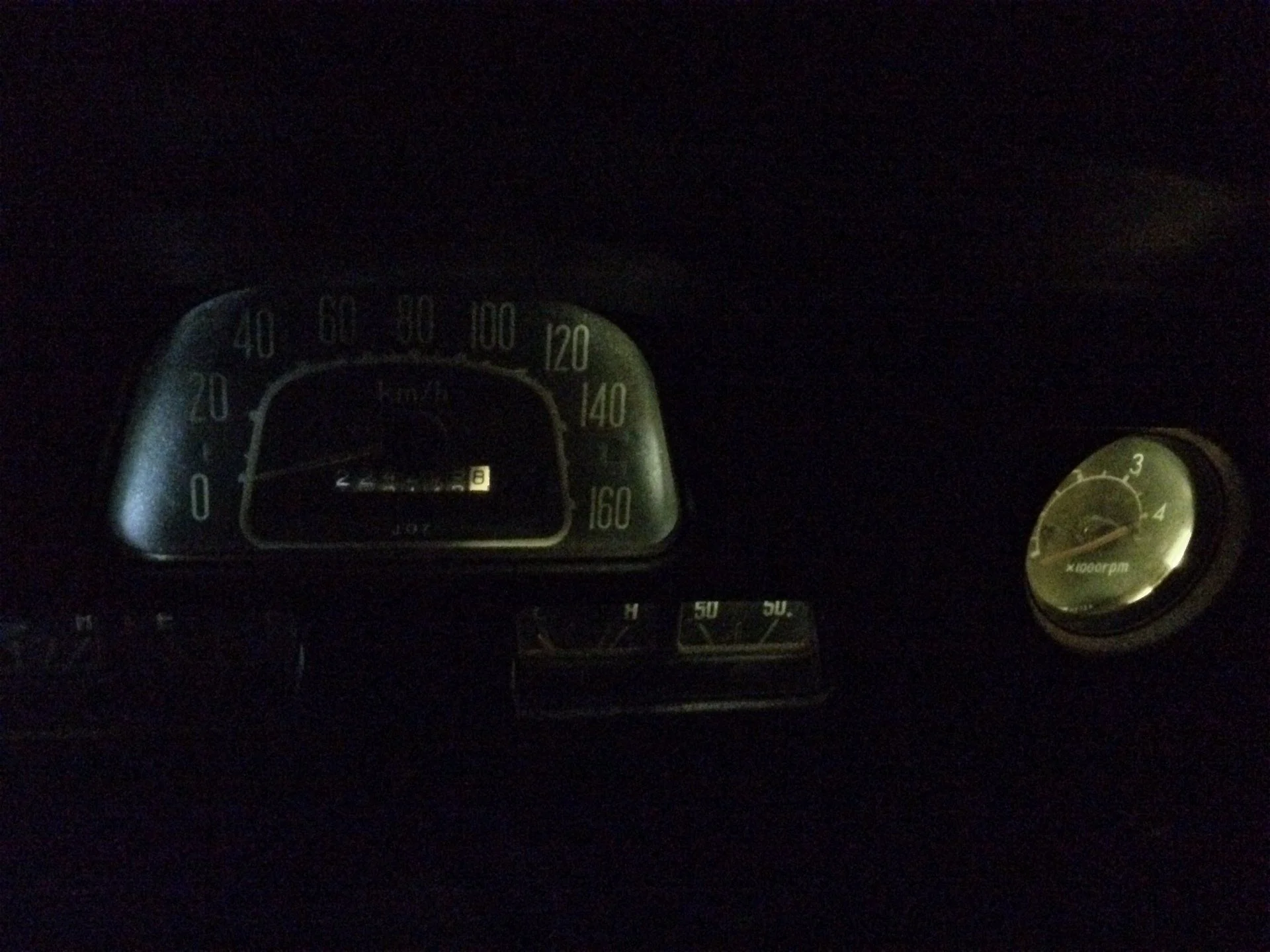
I've been avoiding this issue, overthinking it. I've been putting it off because I thought it would be a time sink as I chased down a bad ground somewhere in the harness.

Finally, the guilt of having had @bj40green generously helping me with my problem and me not following through on his suggestions got to me, so I went out to the truck tonight. I still don't have much confidence in my multimeter skills, so although the fuse showed no continuity, it "looked" OK so I was trying to convince myself that it couldn't be this simple. Thankfully last fall I ordered a dozen or so spare fuses (genuine Toyota OEM!), so I rummaged through my parts stash and found the 15A fuse I needed, replaced it, and lo and behold I had tail lights and, perhaps more exciting for me, I had dash lights!!!


So much thanks to @bj40green to help me get this working. The good news is that I've spent quite a bit of time reading over the wiring diagrams and I feel like I'm understanding more of how things work. Every little bit of confidence gained helps immensely.
 
Of course, one mystery solved just pushes the next mystery/challenge to the top of the heap.

I've had a dangling/damaged male six-prong connector above the transmission that I'd been trying to identify.

male-six-prong-001.webp


I finally pulled the transmission hump so that I could get closer to it and actually follow the wires.

WB and R - Tachometer sensor
L and RL - Reverse light switch
G_ - 4WD indicator switch

All but the G_ for the 4WD indicator switch are in accord with the colors as documented in my wiring diagram, and I chased the Green back and forth and back and forth between this end and the 4WD indicator switch before I convinced myself that this was what it was.

You'll notice in this picture above a sixth, non-stock wire, which becomes more clear in the picture of the female end below:

female-six-prong-001.webp


A butcher job by a helpful mechanic that was trying to get me through brake and light inspection. That's the "new" wiring for the reverse light switch.

What I'm trying to figure out is what the male side of this six-prong connector looks like, and where to source it. There aren't any pictures on @Coolerman's website of the standard 6-pin connectors, so I'm not sure if that is the right part to order.

I'm hoping that I can source the right part and simply replace it, re-wire the currently cut OEM wires for the reverse switch, and end up with a working tachometer, now that I have a working tachometer dash light!
 
More small progress:

IMG_0500.webp


The clock has never worked since I got the truck. I bench tested it a long time ago and couldn't get it working, but again: confidence or lack thereof, I suspected my multimeter skills were at fault. I recently got a new dash panel with all switches and a clock and that one worked! I had to redo the wiring inside the dash, because the Army had reworked it for a blackout switch that had long since been removed by a PO.

Maybe I'll use the old clock as a housing for a Raspberry Pi or something.
 
While I was in there I also replaced the hazard switch with a new one from my new dash panel. The stem in the old switch was no longer connected to the inside of the switch, so it was not functional.

With the new switch, though, I have another Rudy-worthy conundrum for @bj40green. With the hazard switch pulled all the way out, I don't get lights or flashing, though I can hear the flasher clicking. I noticed that if I turned the turn signal on while the hazard switch was on my hazard lights came on and flashed properly.

I also noticed that if I only pulled the hazard switch out approximately 3/4 of the way the hazard lights flash appropriately.

Why could that be?!?
 
Small progress.

Although I understand a lot about how these old trucks work, thanks largely to helpful folks on Mud, I don't have a lot of time or practical experience working on them so my self-confidence is usually relatively low when it comes time to do work.

I spoke of this awhile back with my friend, @65swb45, and he suggested that to get familiar with working on things and build some confidence that I should just take something small, remove it from the truck, clean it, and put it back on.

As is often the case I took the advice and mulled it over for a long period of time while I figured out a plan of action.

Fast forward a few months to this weekend when I was finally prepared to remove the windshield washer bottle and pump. My old pump motor was corroded and no longer connected, and the bottle itself was filthy.

IMG_0637.webp
IMG_0639.webp


I watched some YouTube videos and got to scrubbing and produced this:

IMG_0641.webp

Installed:
IMG_0642.webp
 
Thanks Mark, and thanks for the encouragement, too!

So, as is so often the case with these things, I did not get a perfect score. The new motor works perfectly (bench-tested), but I can't make it work from the wiper switch.

Previously the old motor wasn't plugged in, and the harness plug was instead plugged in to this old thing:

IMG_0645.webp


I think that it was there just to complete the circuit, because it was not attached to anything other than ground.

As far as the non-working washer pump goes, I have done the following:

  • Confirmed that when connected directly to + battery terminal and ground the pump works and squirts water
  • Followed the path of the harness where the Blue (L) and the Blue-Yellow (L-Y) wires travel below the radiator, along the passenger's fender wall, and into the cab and do not see signs of it being cut—mind you I did not open up the loom to visually inspect the wires across the entire run
  • Cleaned the wiper switch and the contact area on the dash panel, though I think from reading the wiring diagram that on my late model truck there is a dedicated ground wire, the switch is not grounded to the frame by the retaining nut
IMG_0643.webp


Since the washer motor works by turning the switch's knob to complete the ground, I'm guessing that somewhere I have a grounding issue. But where is it likeliest to occur? And how best to test?
 
W/B is your ground wire. The switch makes a short between L/Y and W/B.
Test: touch the L/Y on the switch side to bare metal. If motor works.... the L/Y is OK.
If not.... trace the L/Y from motor to switch.

Rudi
 
@bj40green, I wasn't sure of the best way to get at the L/Y on the switch side with the wiper switch still attached.

On the later model wiper switches there are two connectors, one which has the L-Y/W-B separated. I pulled the switch from that connector and jumpered from the L-Y to the W-B on the harness side, and that did not cause the washer motor to engage.

Is that a valid test?

The test is valid. The question now is; is there voltage on the L wire to the motor?
If yes: is there voltage on the L/Y wire from the motor?
If yes: is there voltage on the L/Y wire at the wiper switch?

Rudi
 
@bj40green Rudi, thank you again for your patience and encouragement!

I pulled the test light out of my tool box tonight, disconnected the two-prong connector from the pump motor and tried the following:

  • Probe inside L connector and wire connected to body: light goes on with key in ON position. I think that that confirms voltage on the L wire
  • Probe inside LY connector and wire connected to + terminal on battery: light goes on when wiper switch is turned counter-clockwise (or anti-clockwise as the Antipodeans say). I think that this confirms voltage on L-Y both at the motor and at the switch.
Sadly, reconnecting the two-prong connector to the pump did not result in water squirting from the washer pump. That leads me to believe that the connector is corroded and that although my sharp-pointed test light probe was able to make good contact, the flat connectors of the pump motor do not.

How does that sound for a theory?
 
English is not my 1st language so try to understand what i'm saying.
Did you connect the (sharp) probe trough the insulation of the wire or did you make contact to the female spade connector(s)?
It's possible that the wire is corroded where it goes into the spade connector.
Solution.... buy a new connector from @Coolerman or cut off the connector and replace with 2 new female spade connectors.

Rudi
 
Understood perfectly. I pushed the probe into the female spade connectors.

As it happens, when I bought the new pump I also got a harness (because I thought mine was missing, snivel it was not connected to the pump motor). So I have a brand new female connector, with a pigtail that has proper color-coded Toyota wires attached. It even already has 3M waterproof bullet connectors, ready for me to splice to the existing harness.

Is that the better option at this stage, versus trying to clean up the original connector that's there? The truck is certainly no show truck, so keeping it "all original" is already a lost cause.
 
Yet again, with the sage advice and guidance of @bj40green, I've blundered my way through another one of the electrical gremlins in my truck.

Before chopping into my harness I took a metal nail file and scraped away at the female connectors. Thirty seconds of work, reconnect the pump motor, turn the key and twist the knob (clockwise, not counter-clockwise as I falsely asserted above) and that she blows!!!

It's the small victories that keep me going. Thanks, again, Rudi!
 
You found and solved it! :bounce::bounce2:

Rudi
 
More electrical things to do. This thread is in danger of becoming an "Ask Rudi" thread, I've been so thankful for @bj40green's help thus far.

So with the washer pump motor sorted out, it's time to shift to the intermittent wipers and that wonderful little marvel of 1980's Toyota engineering, the wiper control relay.

IMG_0678.webp


Prior to removing the relay I would get a slight burning smell when I tried the wipers on the intermittent setting. Opening it up I found a fair heap of dust right in between the contacts. I'm pretty sure that that was the source of the burning smell.

I cleaned the innards with some electrical contact cleaner and some 400 grit sandpaper. The gears were spinning freely so I did not elect to regrease them.

IMG_0682.webp


Once I put the relay back in, I tested the wiper mechanism with my windshield wiper blades and arms removed—I was paranoid that I might burn up the motor or something vaguely weird like that, I guess.

I observed that I could hear the small motor inside the relay engage, and I watched the posts on which the wipers are attached spin in what looked like the correct motions on the low and high settings, but on the intermittent setting they didn't seem to be going in exactly the right way. Or at least not in the way that I expected. There was a delay, but it did not go in a distinct pattern of "counter-clockwise half turn, clockwise half turn, delay, repeat" pattern that I was expecting.

Thinking I might just not be that good at conceptualizing things I decided to attach the wipers. I confirmed the low and high settings were working properly, but at that point the intermittent setting seemed to no longer be working, and I didn't hear the relay's motor working anymore.

I tested voltage on the harness connector. There is a constant 12v on the L, and nothing on LO, LW or LY, which I think is correct as per the diagram I posted in #30 above.

So I think I need to bench test the Wiper Control Relay, but I'm not quite sure of how to go about that, and I'm a little concerned that I might damage it.

I think I need to apply 12v to the L post, hook up the WB post to ground, and then I think I need to jumper across LO and LW in order to engage the motor. Is that correct?
 
Hi Thomas,

Do you have another diagram? I think there is an error in this diagram, especially in the wiper motor diagram.
Have a look at the wiper motor; bottom is connected to B (battery) via the L wire.
Top +2 (= high) is connected to L/B switch B to L wire. Which is plus 12V to plus 12V.
Same goes for +1 (= low) is connected to L/R switch to B to L wire. Which is also plus 12V to plus 12V.
The wiper motor is nowhere connected to ground.

Rudi
 
Last edited:

Users who are viewing this thread

Back
Top Bottom