Help with 3-link on '99 4-Runner (1 Viewer)

This site may earn a commission from merchant affiliate
links, including eBay, Amazon, Skimlinks, and others.

Not a problem. I've put alot of thought into this and have already come to grips with the fact I will not be able to build the "perfect" suspension given the vehicles restraints. I'm just trying to aviod the :doh: factor. I'm already conviced the truck will be amazing offroad....it's the streetability I'm trying to consider.
 
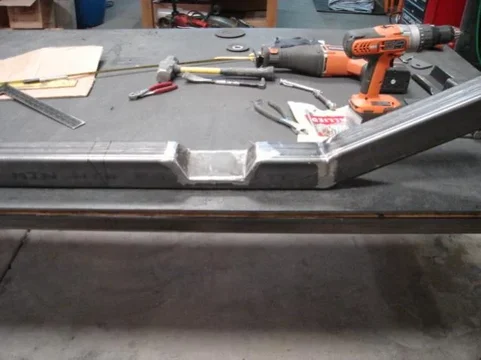
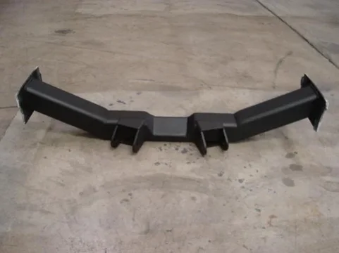
Got around to building the rear axle truss today. I used a piece of 3" x "4 x 3/16" square tube about 4' in length. I wanted a flat plane to mount the upper links above the diff and needed to build up to the 1/4" link mounts. The extra strength won't hurt either. This is the tube with the bottum cut off and notched for two bends. I beveled the cuts back for good penetration so I could weld them up and then grind them back smooth.
rear axle 001.jpg
Here's the truss after welding and cutting out the shape. It took three pieces of cardboard to get it right.
rear axle 003.jpg
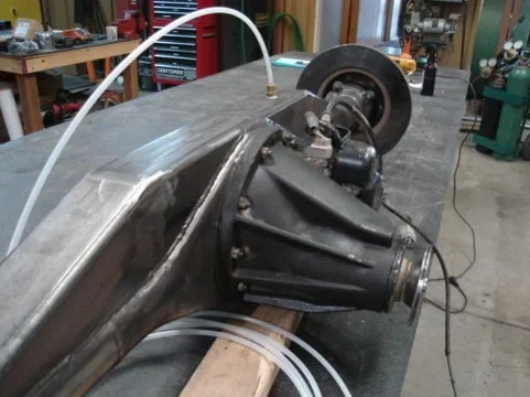
I had to run a hose for the diff vent through the truss. It will end up in the back of the Heepetr for deeper water crossings.
rear axle 004.jpg
rear axle 001.jpg
rear axle 003.jpg
rear axle 004.jpg
 
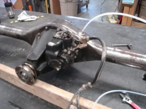
The truss in place on the axle. I welded in on in about two inch sections, moving around and giving it time to cool in between.
rear axle 005.jpg
Here it is all burned in.
rear axle 006.jpg
The vent tube ran from a barbed fitting in the original housing and then through a compression fitting I drilled out to keep water out of the truss.
rear axle 009.jpg
rear axle 005.jpg
rear axle 006.jpg
rear axle 009.jpg
 
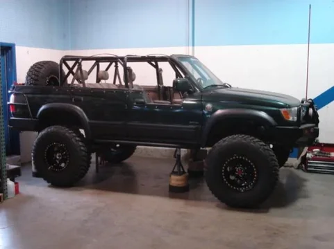
Thanks dragr1. I got some time to finish the roll cage. I won't have to worry anymore about how I should have done that rinforcing I'd been meaning to do. Here's a couple pics in primer.

[/ATTACH][/ATTACH]
rear axle 002.jpg
rear axle 003.jpg
rear axle 001.jpg
 
Thanks dragr1. I got some time to finish the roll cage. I won't have to worry anymore about how I should have done that rinforcing I'd been meaning to do. Here's a couple pics in primer.

[/ATTACH][/ATTACH]

Looking good. Hey, I got a green 3rd gen now, I'll just send it on out for some work! Unfortunately I have a friends '94 80 series on jack stands in my carport right now that we're trying to install caster plates-not fun!
 
Last edited:
That 80 build is very similar to what I have in my head. The tower will be on the tube instead of the center section and I'm going to build some adjustability into the upper frame mount but otherwise very close. Thanks

Dragr1 send 'er up!:)
 
Well I re-installed the cage tonight. Got it painted over the weekend. Brackets started showing up today. I thought about building my own but decided in the end to order them. Without a plasma or a drill press it just didn't seem worth it. I put the rear axle on stands in the back and got most of the interior back in as well. I don't think I have much time for it this week but will hopefully start tacking things in this weekend. Here's a couple pictures with the rear axle and cage back in.
[/ATTACH]
rear axle 001.jpg
rear axle 002.jpg
 
That 80 build is very similar to what I have in my head. The tower will be on the tube instead of the center section and I'm going to build some adjustability into the upper frame mount but otherwise very close. Thanks

Dragr1 send 'er up!:)

I noticed that he used only right hand threaded johnny joints. Adustability and setting up the position of the axle would be a pain.

If you fit LH and RH on each end you get easy adjustability.

His stated reason for not doing this is to only have one spare part which covers most of his needs.

Just had a look on their web site - they are available in either thread

Johnny Joint®

:)
 
If you have a reasonable amount of frame flex, that Tcase mount will snap your tcase in short order.
 
I am using all right hand joints as well because I am using a fixed johnny joint at the frame end (solid notched and welded to the link) and therefore only the axle end will be adjustable for length.

Mace...the transfer case mount uses urethane mounts between the cross member and the frame and is a proven design from Front Range Off Road. Also all six of my cage mounts are tied directly to the frame so it's pretty stiff anyway. I always appreciate the input though!
 
Last edited:
I am using all right hand joints as well because I am using a fixed johnny joint at the frame end (solid notched and welded to the link) and therefore only the axle end will be adjustable for length.

I was just getting a little hung up on the fact that single ended adjustment means fairly coarse adjustability - you can only rotate the joint end 180deg before you can get the cross bolt back in.

If you are going for the 1.25'' 12tpi joints then each 180deg = over 40 thou.

That seems a lot to me but only because I am a toolmaker used to working to microns.

NOT really necessary in this app lol - I think I'm just being a little bit anal.

Keep it up because I am very interested in a three link front. It's probably my next project after my turbo build.

:)
 
Boyo, love the enthusiasm but unless I'm mistaken...adjustability on both ends may give you more adjustment but not neccessarily a finer adjustment. If 180 turn is .04, regardless which end you turn you are limited to adjustments in .04. The joint end (no matter which end) must still be turned 180 degrees to be re-aligned with the bolt....no?

No...you're right... by turning the link itself....infinite... well damn it... wrong again. I mean... yeah...that's what I meant...:hmm:
 
Last edited:
I'm as happy as a little boy on Christmas today. I returned from work out of town to find my wheels had finally arrived. My puppy had been at home alone so I had little time but I still had to take a poser shot to see what they would look like mounted up. It will cost me 40 some odd bolts tomorrow though. These pictures are without valve stems and therefore air.
tires 001.jpg
Still gets me excited though.
tires 002.jpg
Also I got my steering arms taper reemed so that I could mount the drag link upside down. This will improve up-travel by almost 2 inches. Here's a picture after it was re-installed. I think it might make the hydro assist easier as well although I won't know untill I do it.
tires 003.jpg
tires 001.jpg
tires 002.jpg
tires 003.jpg
 
Last edited:
Boyo, love the enthusiasm

No...you're right... by turning the link itself....infinite... well damn it... wrong again. I mean... yeah...that's what I meant...:hmm:

Ha, but obviously only works if your links are straight. Any bends in them for clearing tie bars etc and it's back to your single end adjustment.

Those new boots are looking great - get those axles mounted now so we can see them in all their glory.....
:D
 
I went and got six valve stems this morning (one for a spare) and spent some quality time with a torque wrench, an air compressor, and a ratchet strap. I was able to get all five wheels done in about four hours.
tires 006.jpg
I mounted all of them so that I'll be able to adjust my wheelbase and try to get as much up travel without rubbing.
tires 004.jpg
I also confirmed the rest of the brackets should be arriving on the 7th. Here's what I have layed out so far. I need to weld up one more link and noticed I'm a jam nut short. I have everything for the front already except the lower link axle mounts. I am getting very anxious as this part of the project is coming to a head.
tires 002.jpg
tires 006.jpg
tires 004.jpg
tires 002.jpg
 
The brackets for the rear showed up so it was time to start mocking the suspension. First thing for me was to build a new crossmember to hold the frame end lower links. I used 3" x .25 square tubing. I had to ramp out the middle to allow for full downtravel of the driveline. I wanted to build this crossmember only once and therefore had to put it far enough away from the t-case to allow for a doubler later.
4-link 005.jpg
With some bending and welding it began to take shape.
4-link 006.jpg
This is the crossmember after is is already back out of the truck and being finished.
4-link 015.jpg
4-link 005.jpg
4-link 006.jpg
4-link 015.jpg
 
Here's the crossmember finished. I was pretty proud of the way it turned out.
4-link 018.jpg
This is the rear mocked up. The crossmember is not finished in this picture. Also I have done some finish welding on the rear axle although it is not completely finished as of yet. This setup yeilds almost 8" of up travel and about 10" down. If anything is glaring anyone in the face however please share.
4-link 009.jpg
Another picture from the side. Nothing on the frame has been burned in, only tacked or clamped. The crossmember sits about 3" below the frame which helps for verticale separation and will become a mounting point for a t-case skid plate down the road.
4-link 010.jpg
4-link 018.jpg
4-link 009.jpg
4-link 010.jpg
 
Last edited:

Users who are viewing this thread

Back
Top Bottom