Gudmundur 3.0 - Build (1 Viewer)

This site may earn a commission from merchant affiliate
links, including eBay, Amazon, Skimlinks, and others.

It's looking great! You're an inspiration to us all!

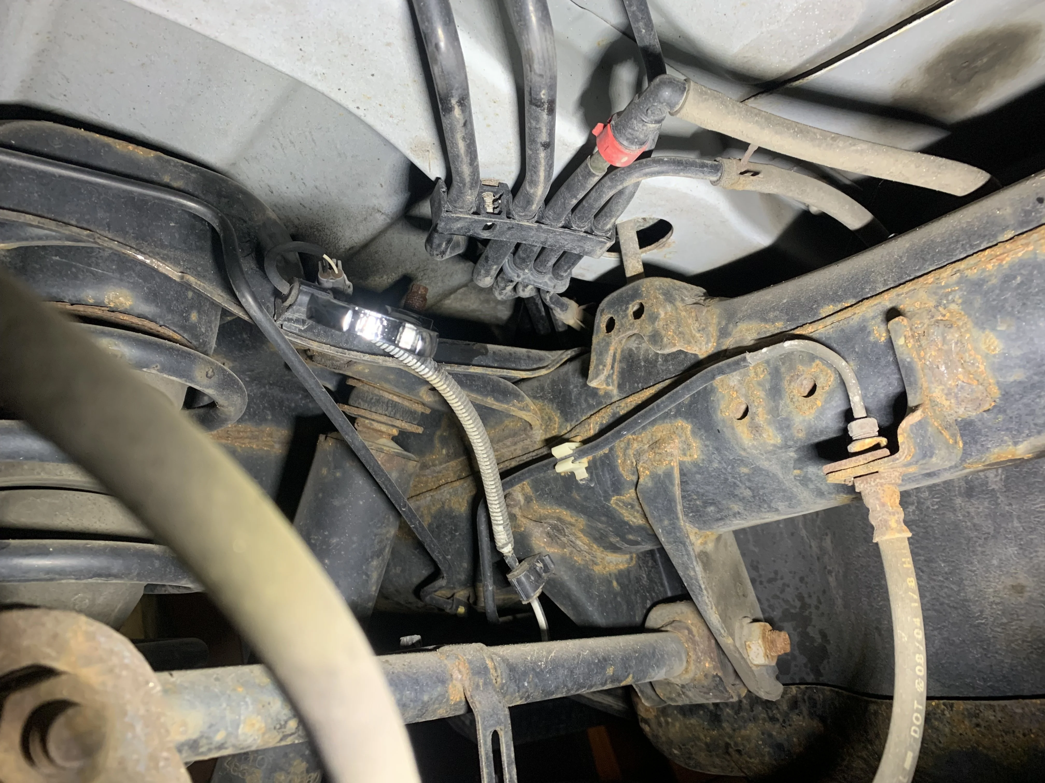
Just out of curiosity, how easy is it to remove the wire loom that runs up the side of the windshield? I'm wondering what a windshield replacement would look like.
It is easy to remove. Just held in with friction. Can also unplug the wires at the light bar if needed if there isn't enough slack.
 
Can I ask a dumb question about the SwitchPro install? I'm about to go down this path but I will be connecting already installed lights (reverse lights, front floods, front light bar, rear light bar) into it. All of these are wired with relays and fuses already. Would I run *only* the switch portion of the circuit to the SwitchPro or do I completely eliminate the relays with the SwitchPro system? This isn't very clear to me from install videos, it seems like almost everyone is starting off with the SwitchPro and installing auxiliary lighting at the same time instead of retro-fitting a SwitchPro. Thanks in advance, I'm in awe of your install!
 
Can I ask a dumb question about the SwitchPro install? I'm about to go down this path but I will be connecting already installed lights (reverse lights, front floods, front light bar, rear light bar) into it. All of these are wired with relays and fuses already. Would I run *only* the switch portion of the circuit to the SwitchPro or do I completely eliminate the relays with the SwitchPro system? This isn't very clear to me from install videos, it seems like almost everyone is starting off with the SwitchPro and installing auxiliary lighting at the same time instead of retro-fitting a SwitchPro. Thanks in advance, I'm in awe of your install!
SwitchPro would replace everything even the switches. It is a solid state unit and has the relays/fusing built in.

You would wire the already install devices directly to the switch pro wiring outputs.
 
Thanks for the clarification, I really appreciate it!
 
Finally got the Slee rear bumper from GUD2.0 put on. Installing it was a :banana: 
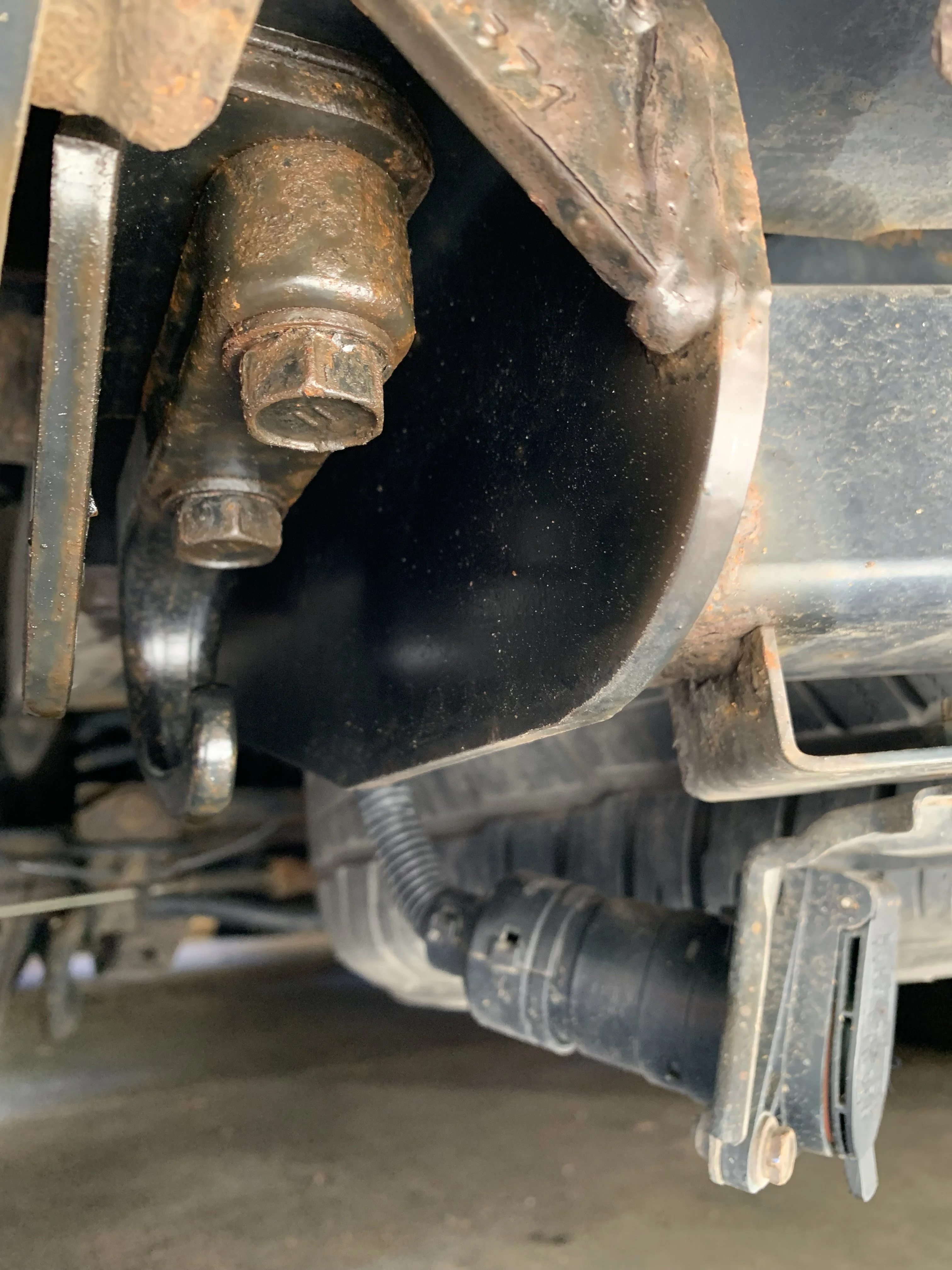
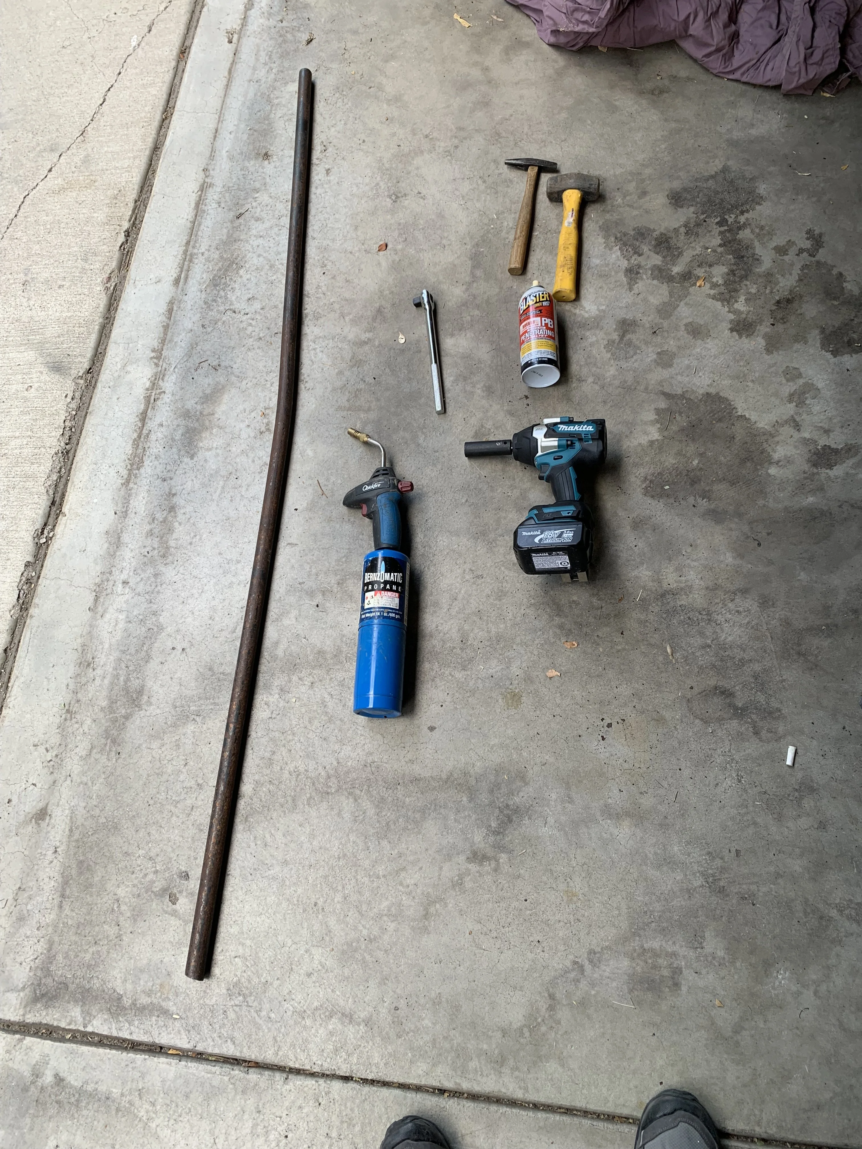
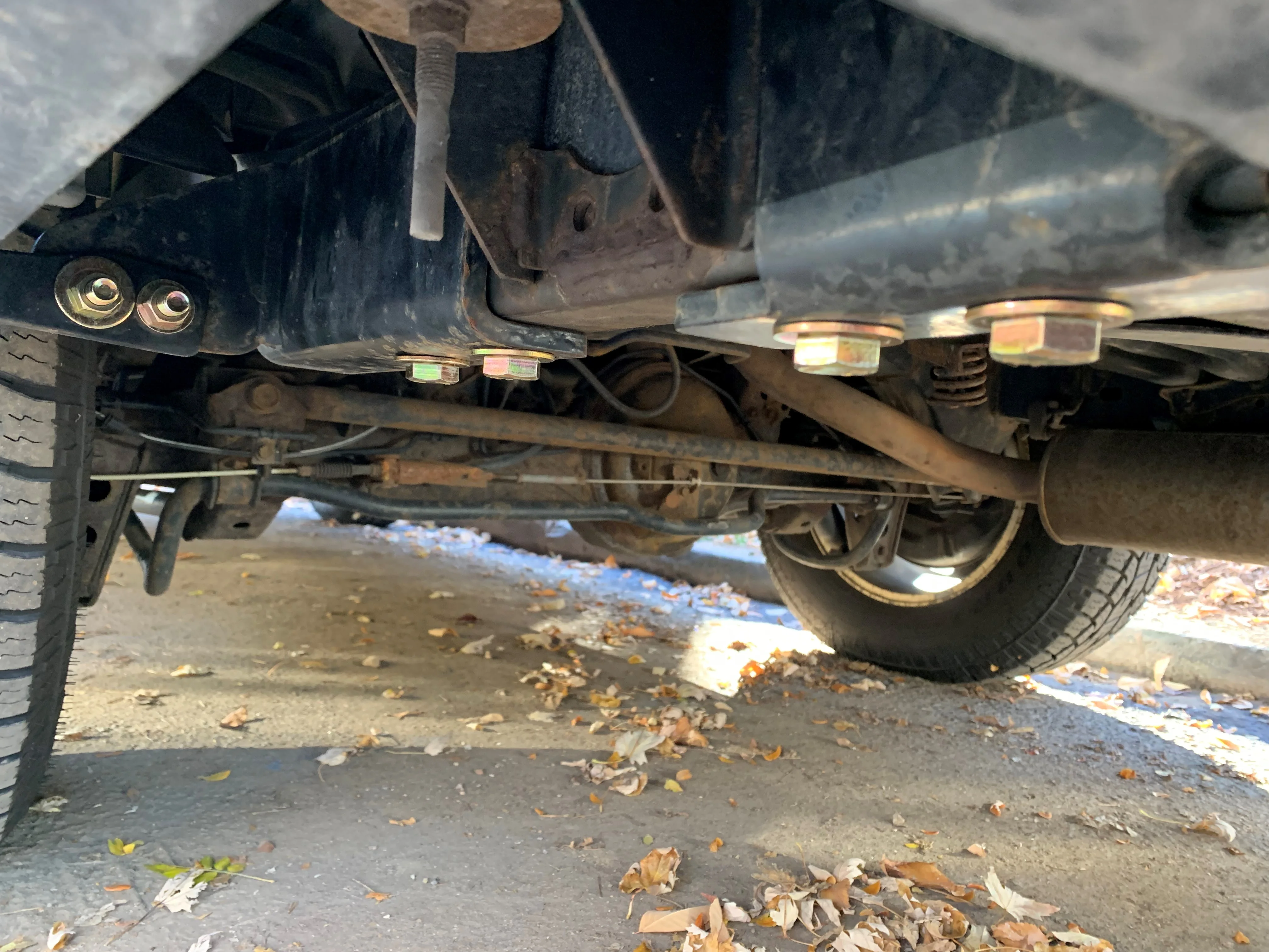
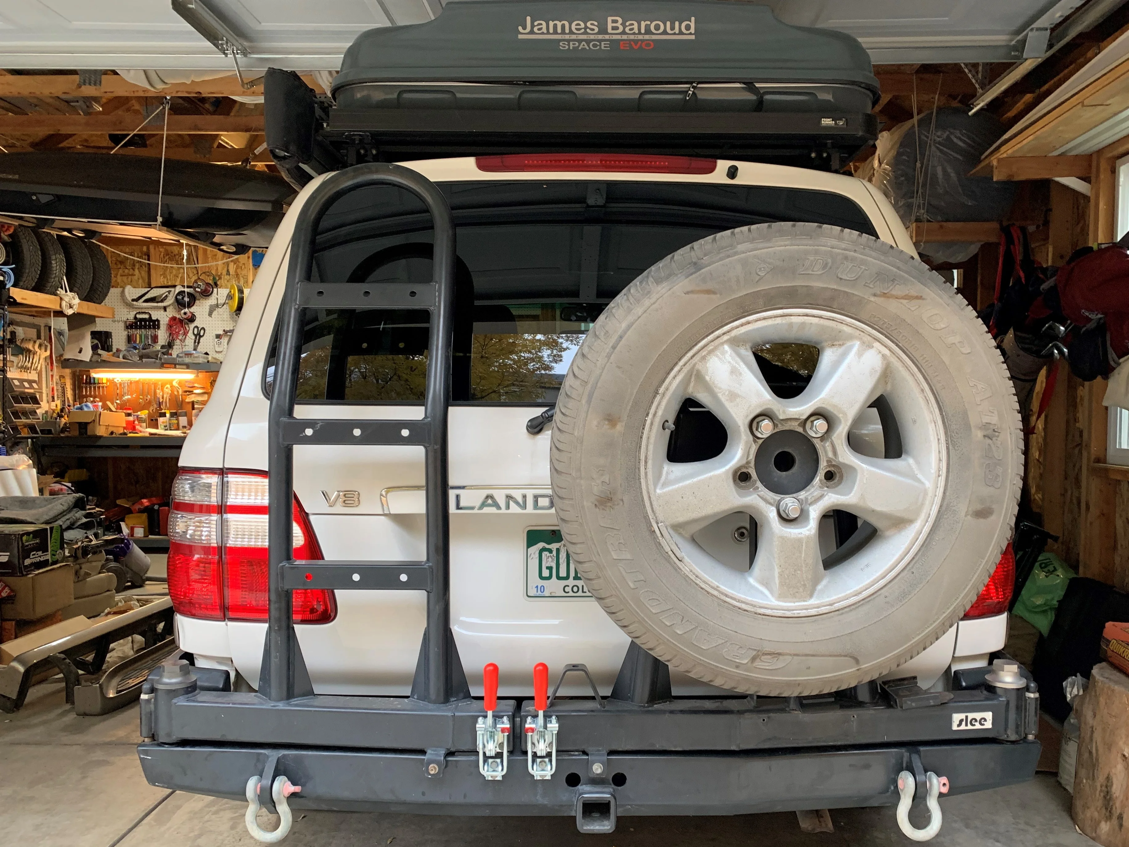
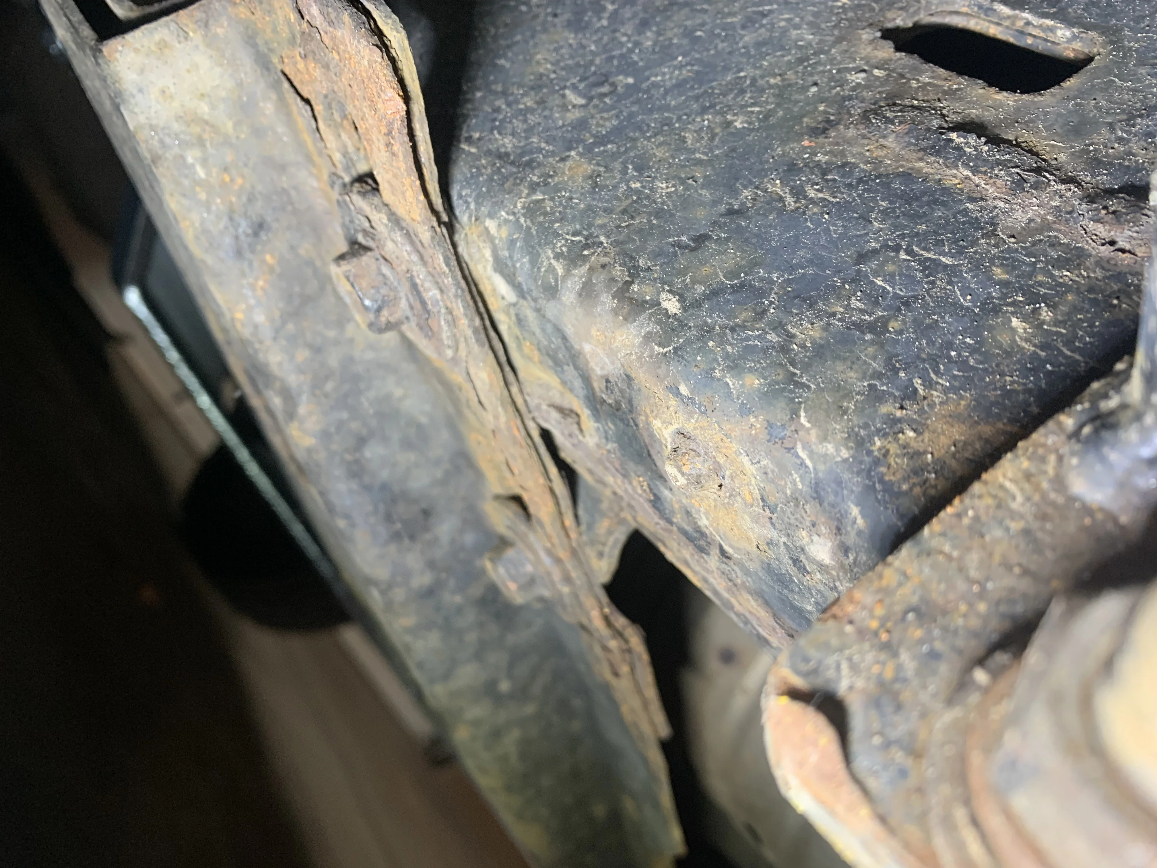
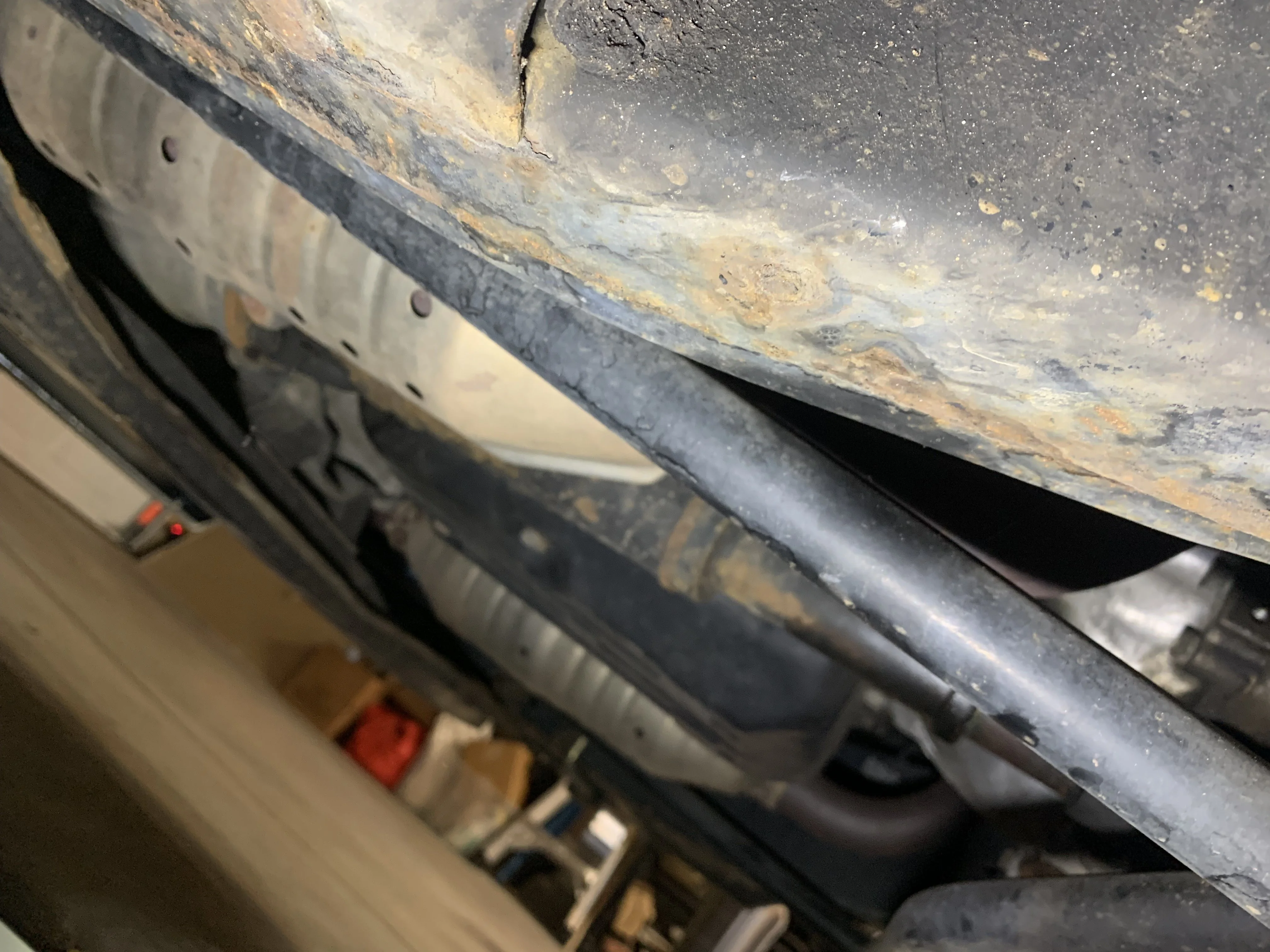
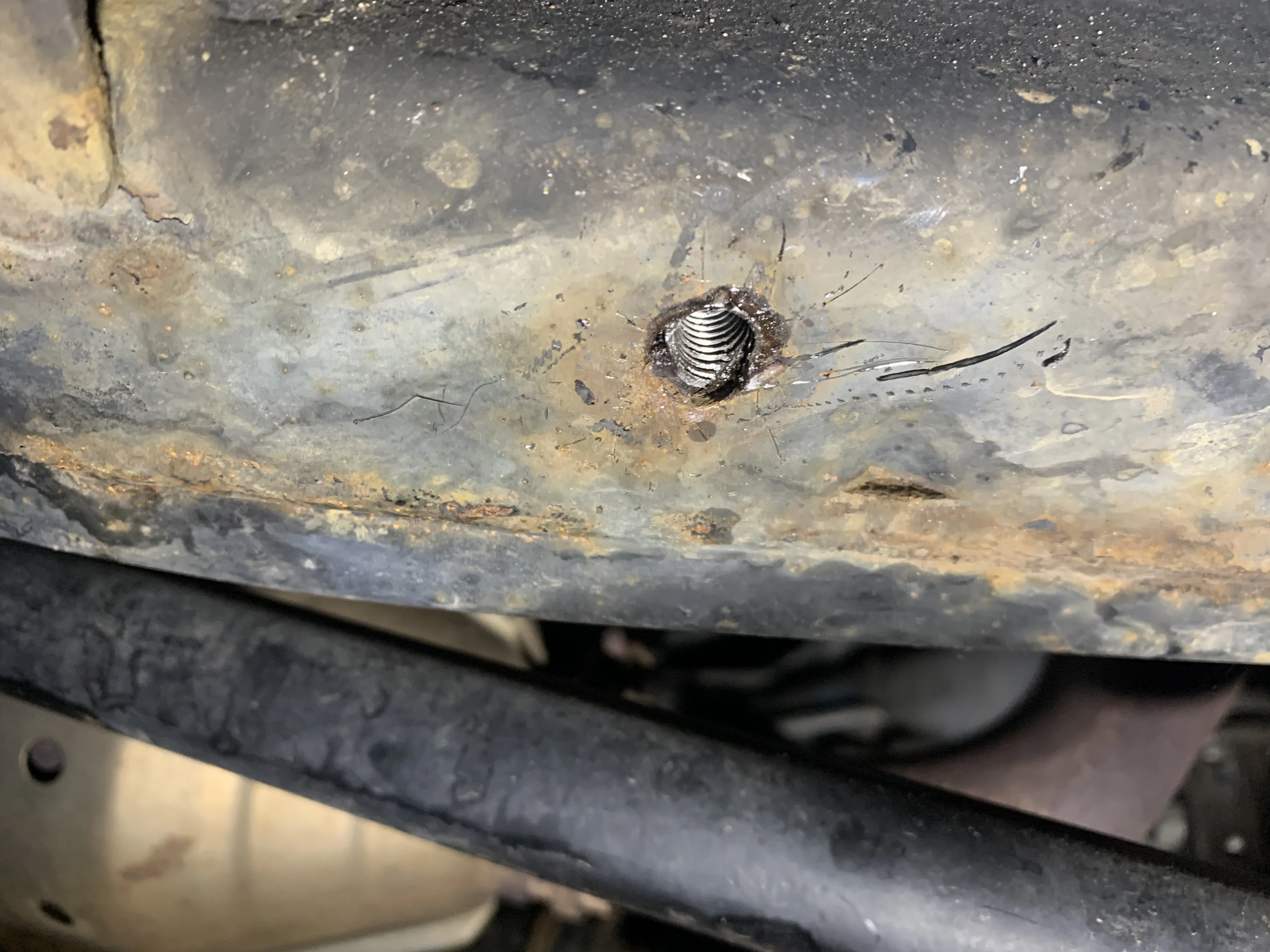
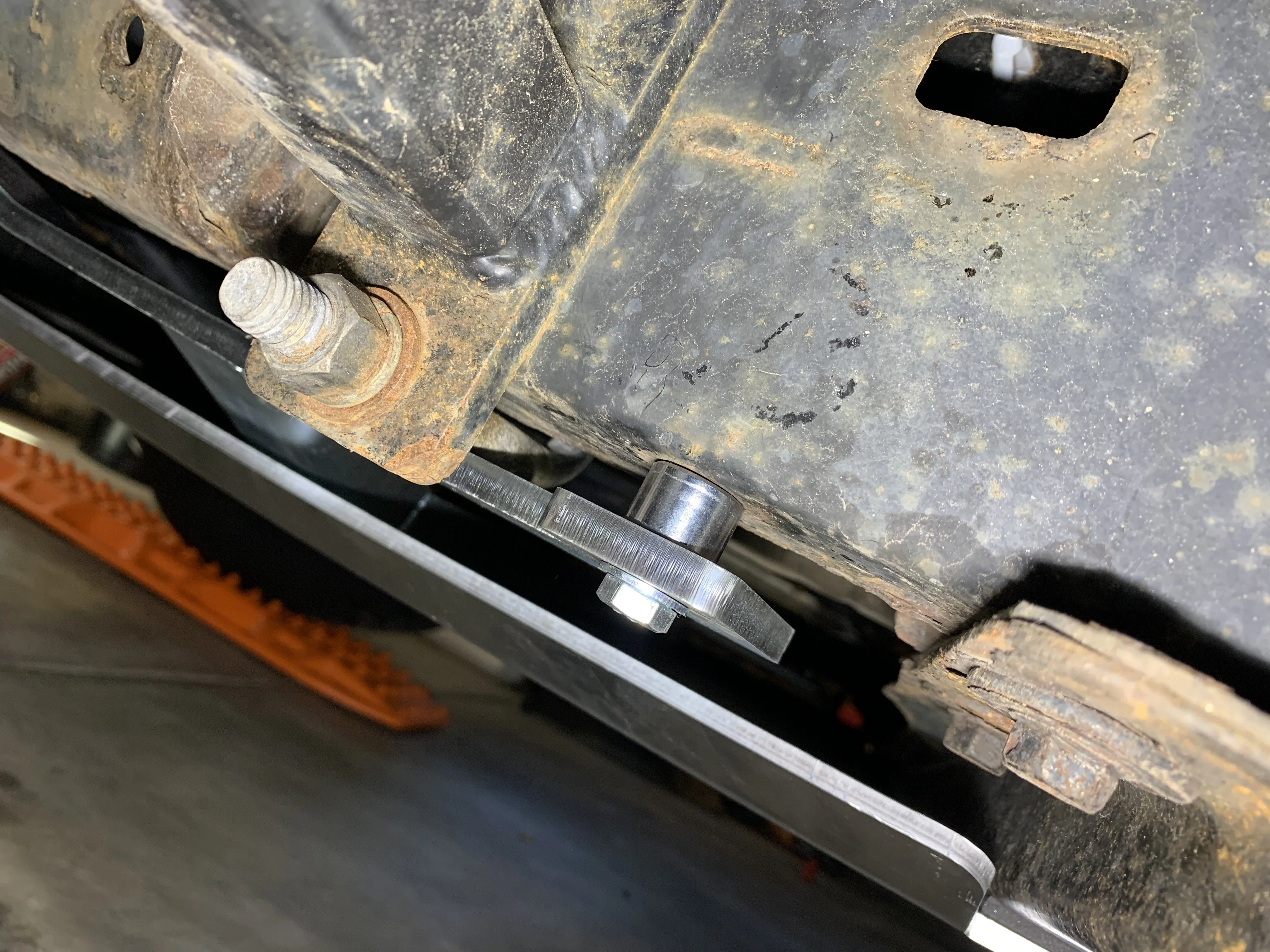
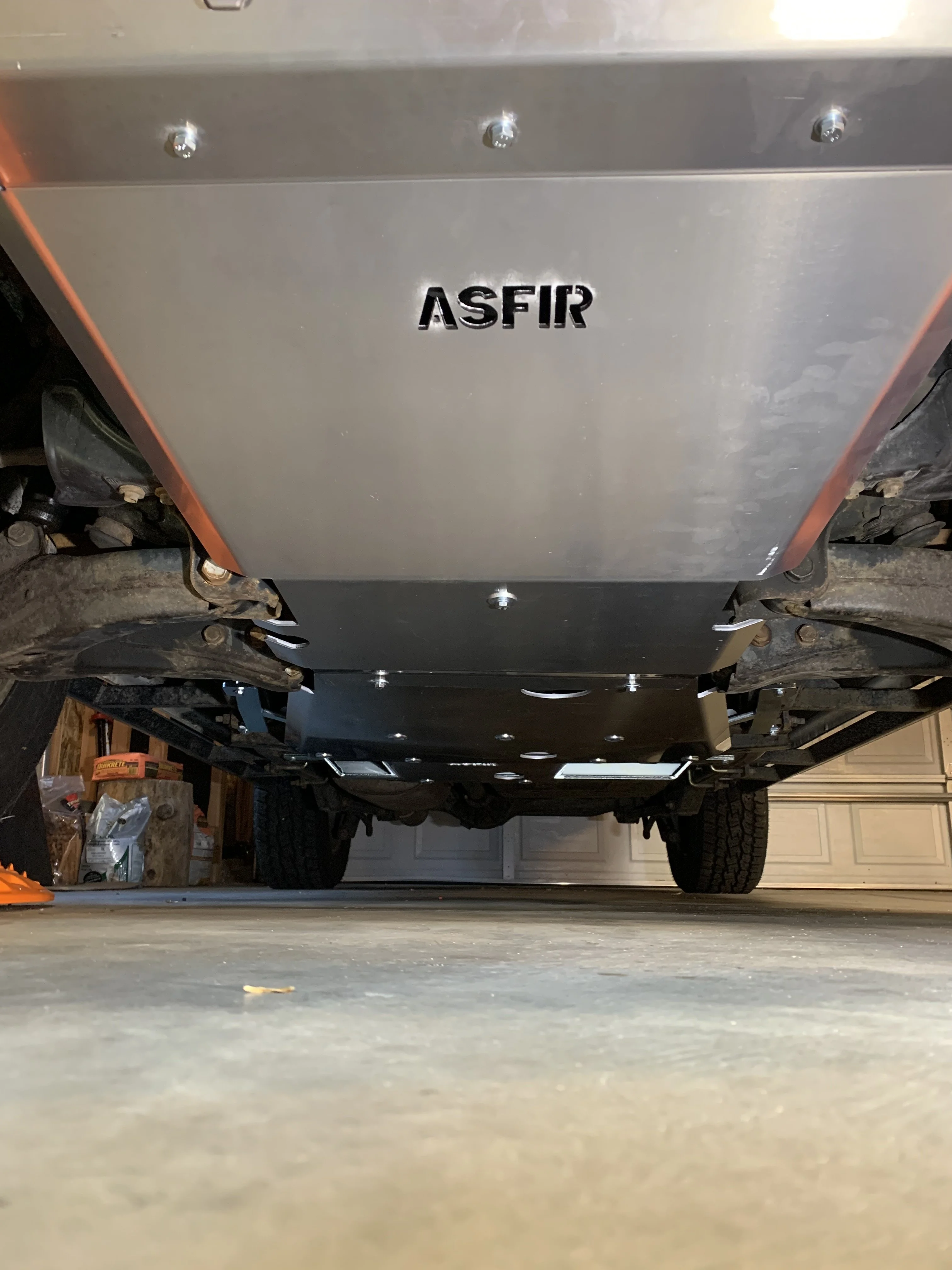
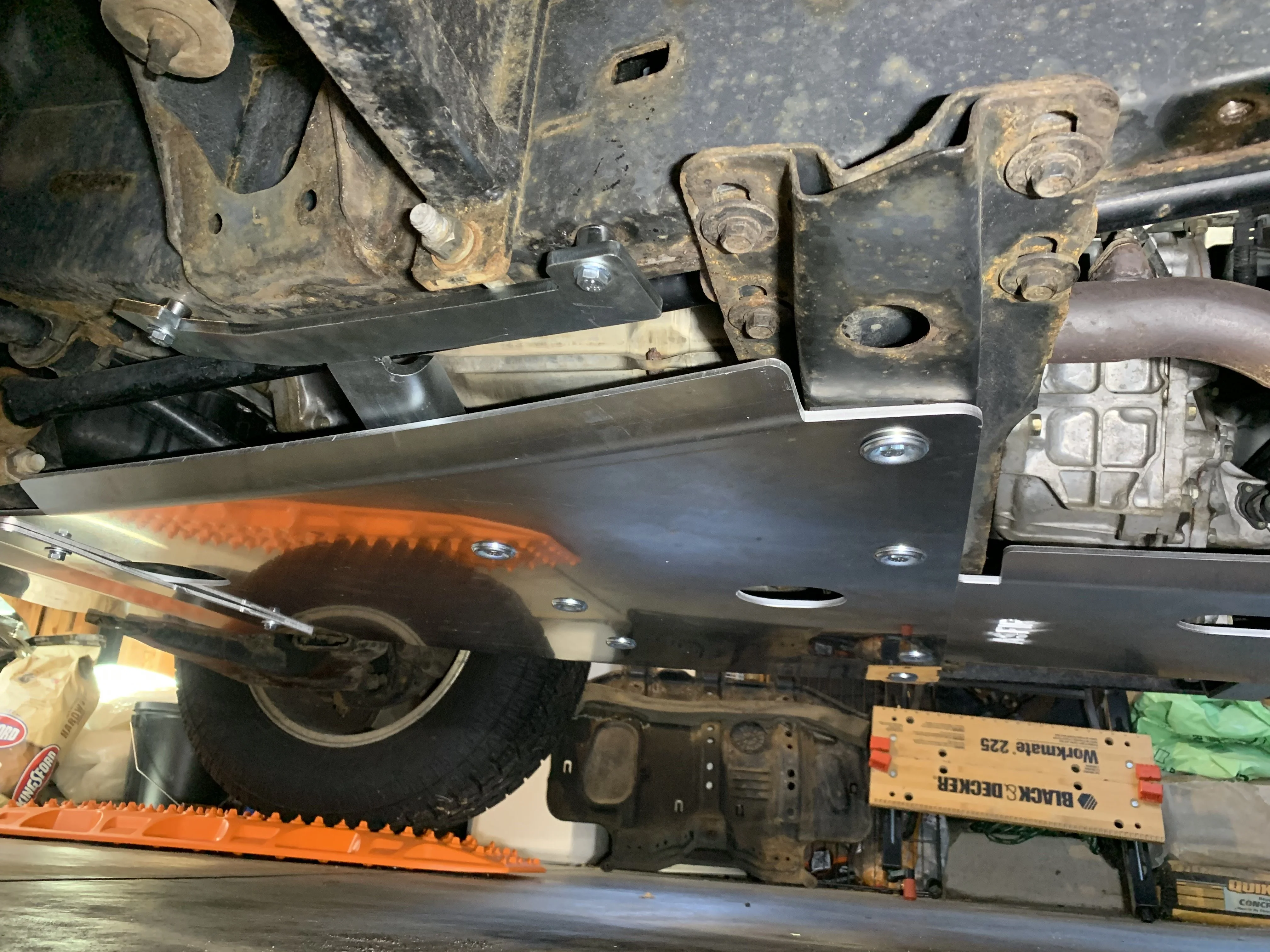
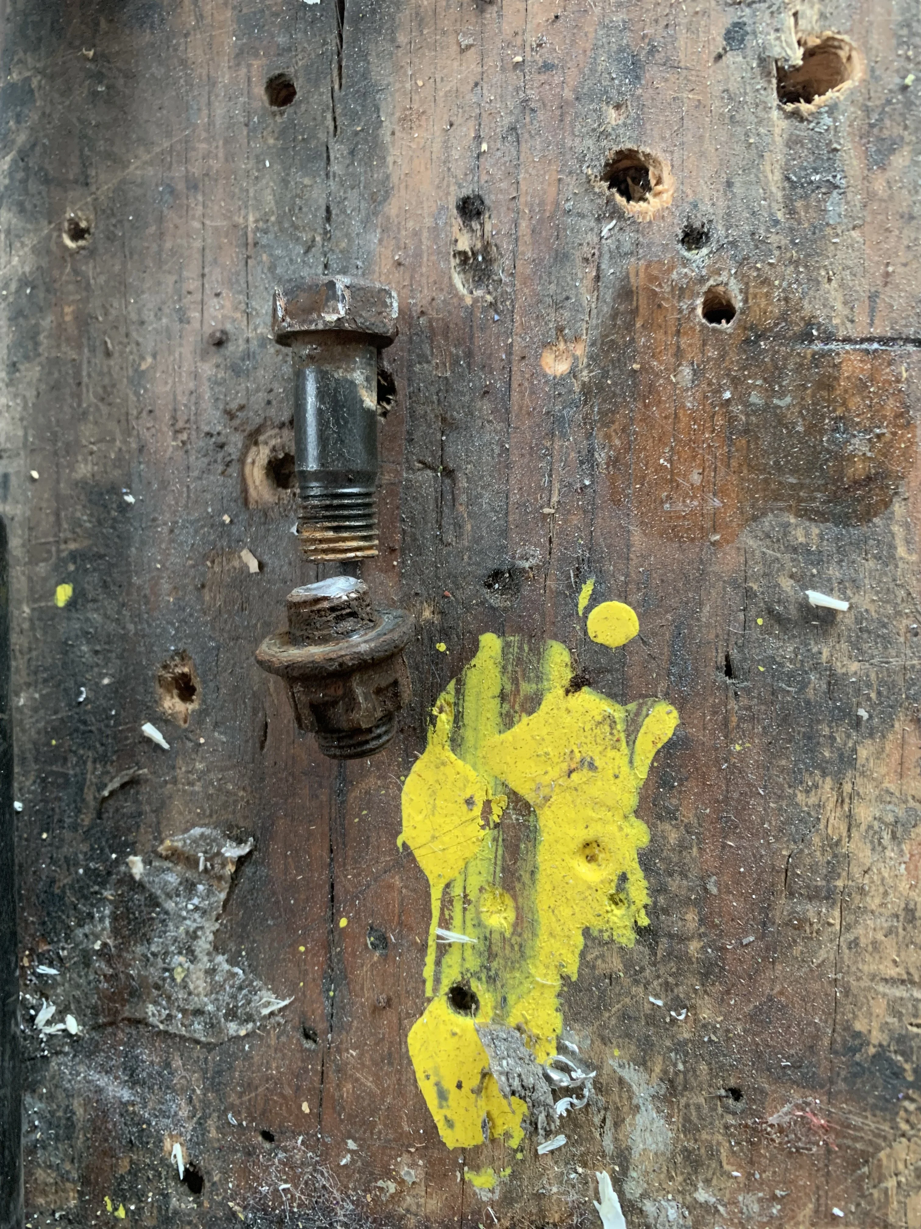
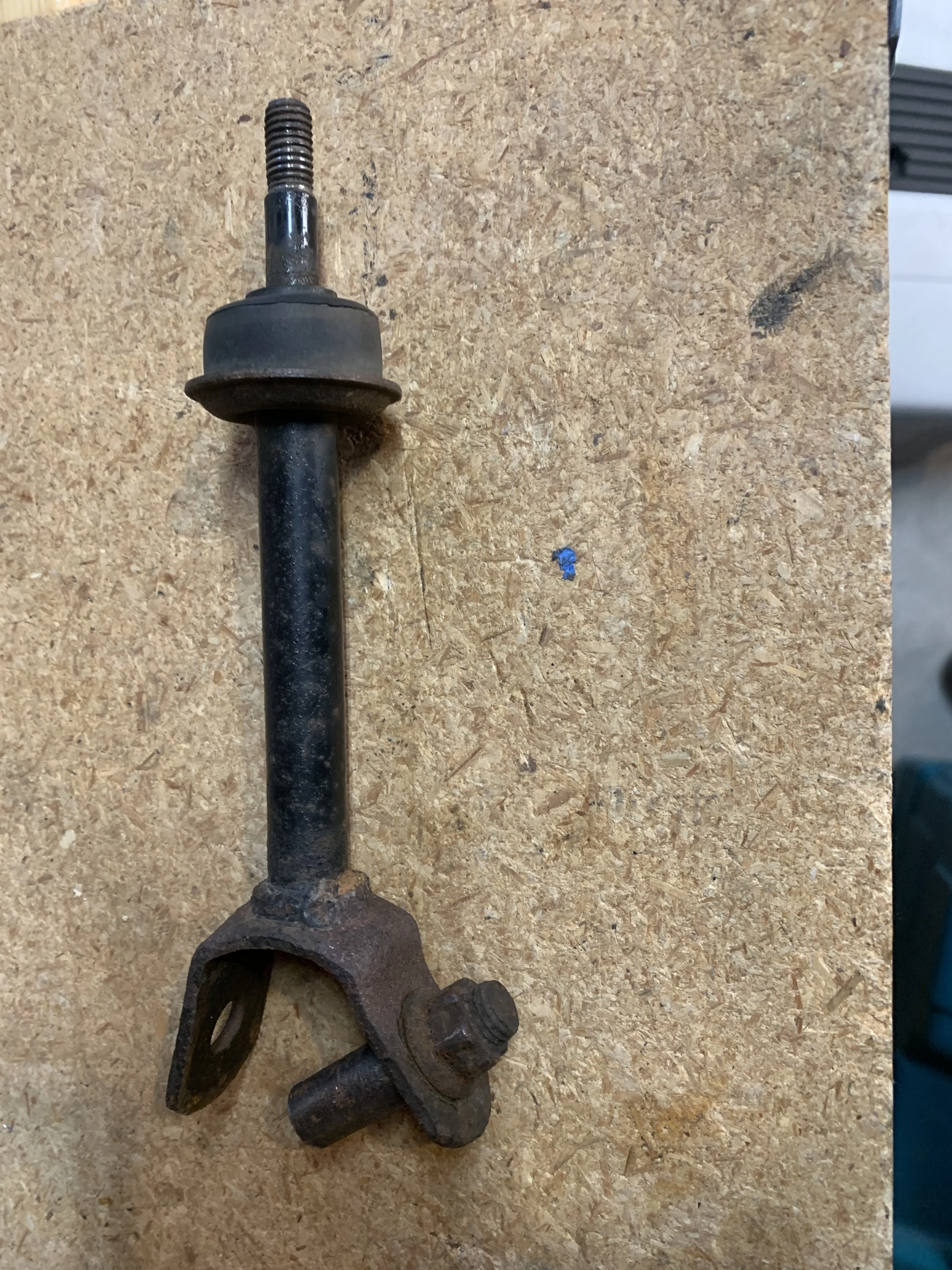
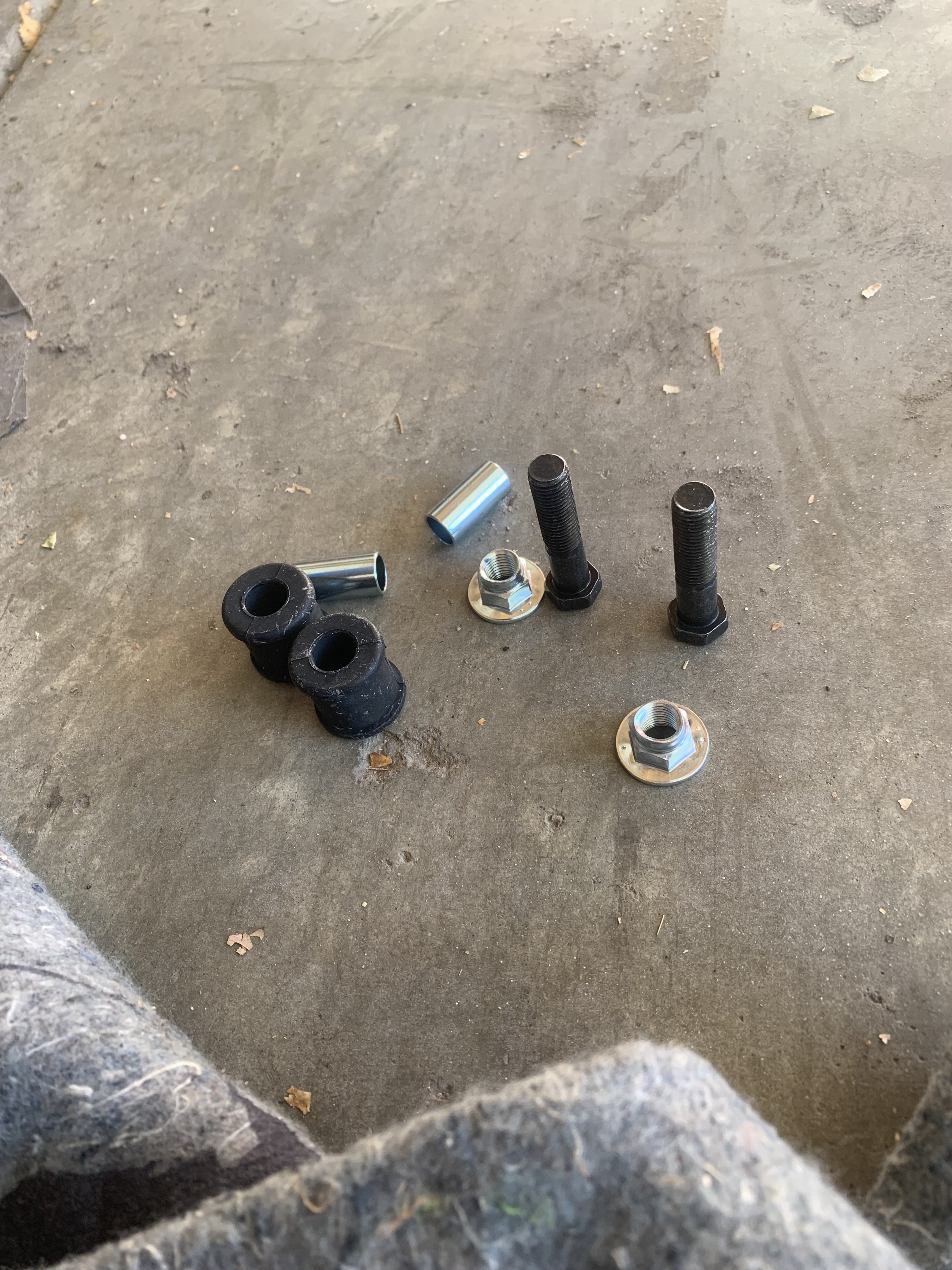
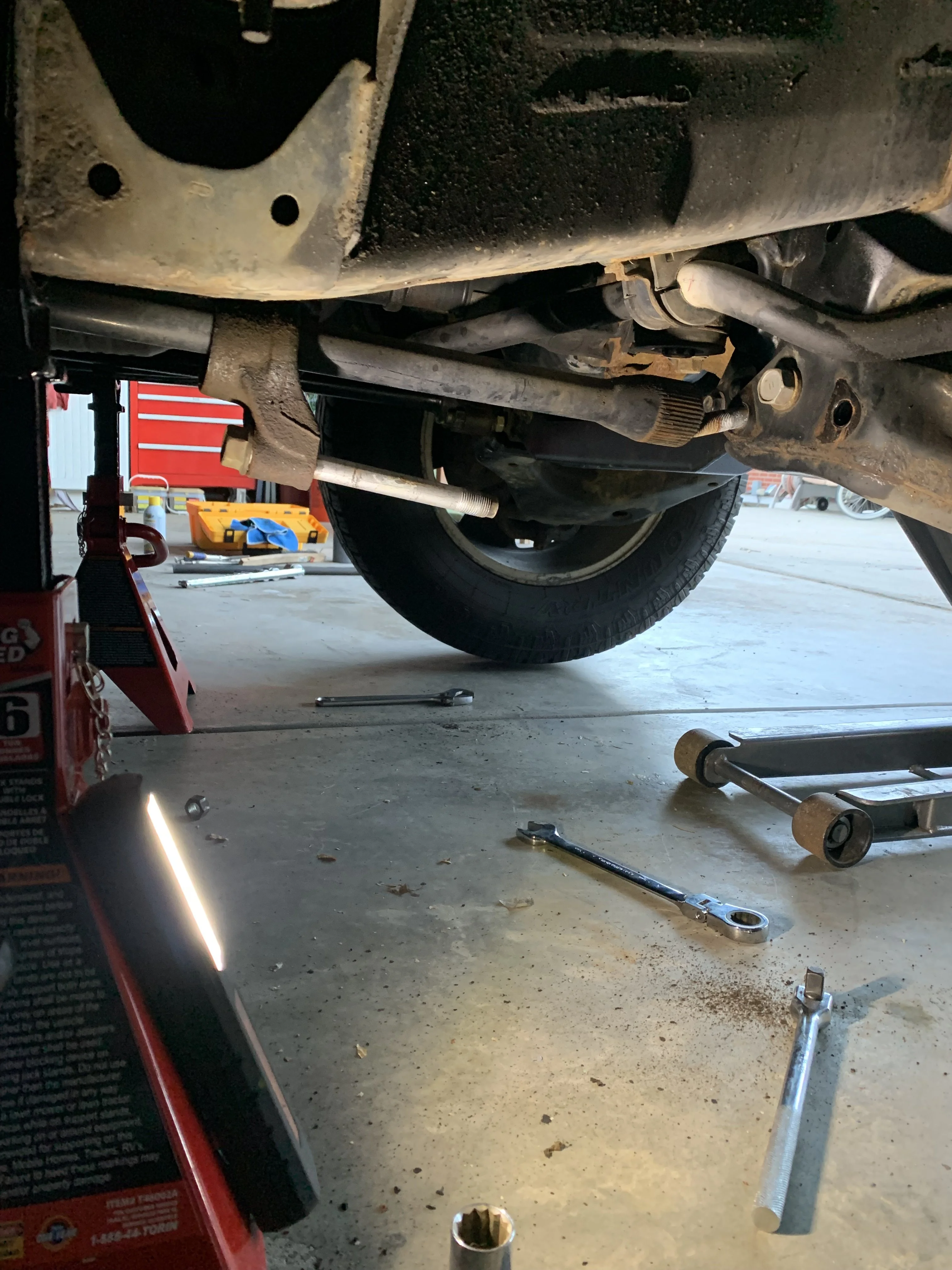
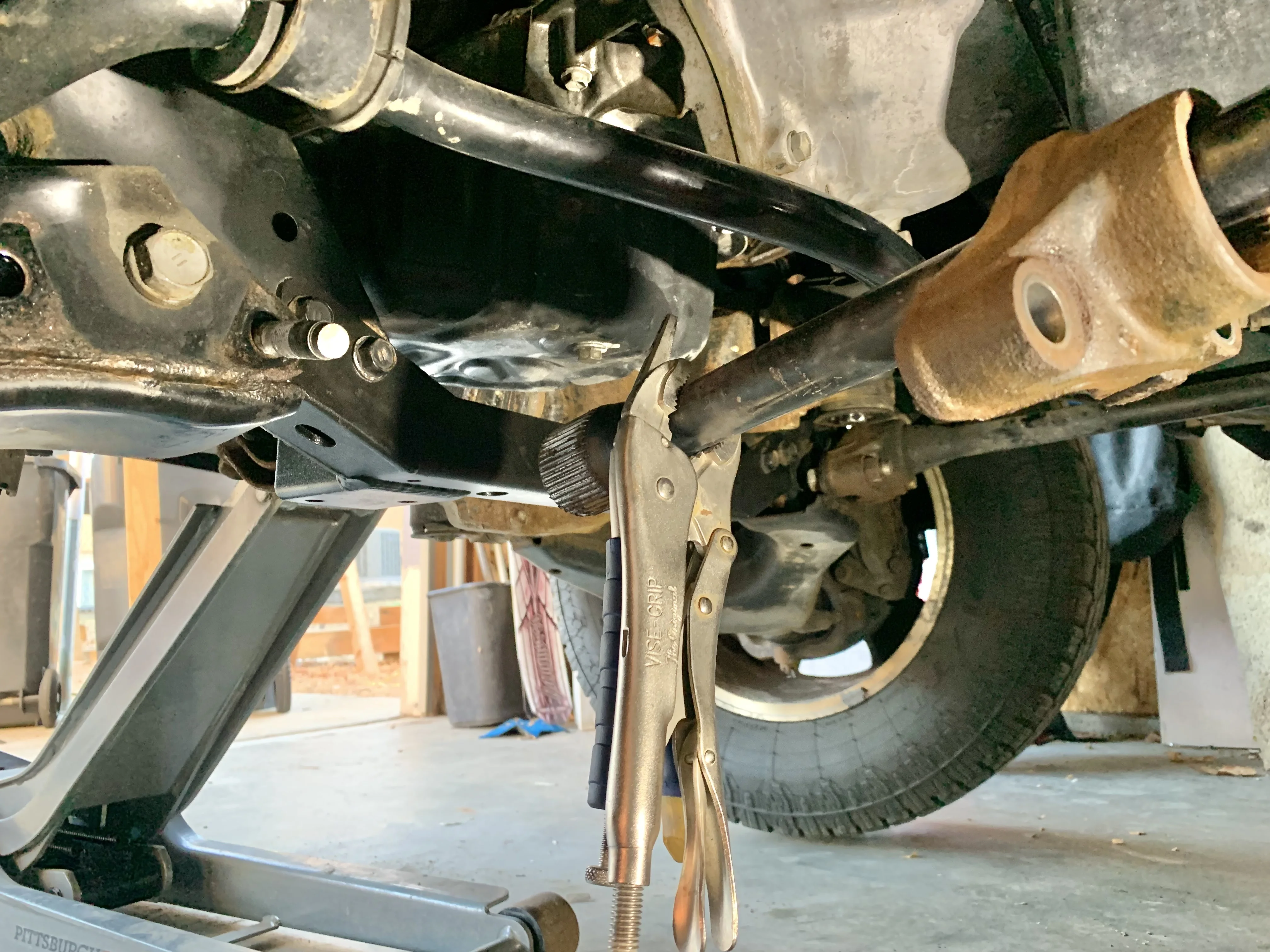
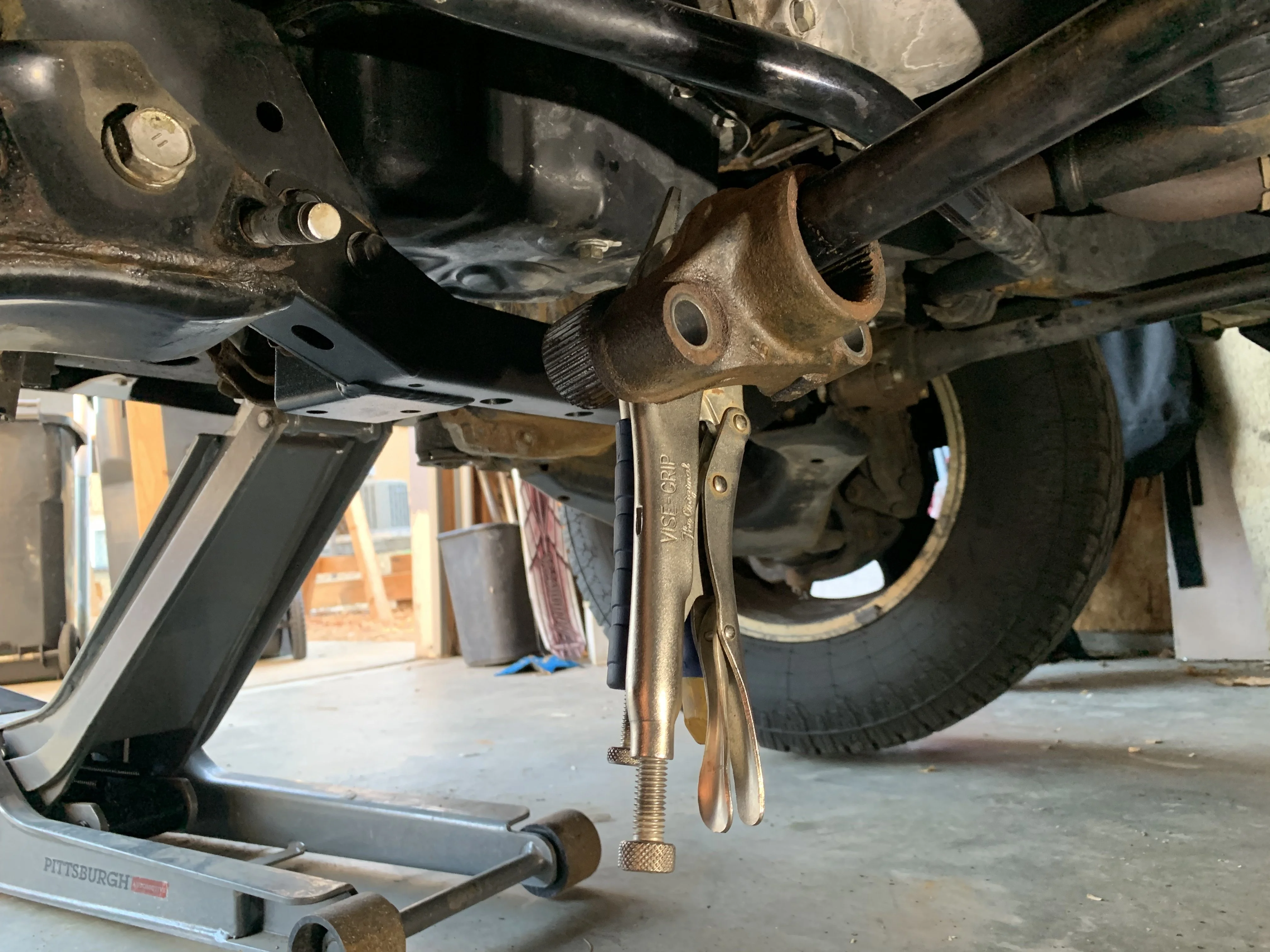
job. Getting the OEM trailer hitch was a pain. GUD3.0 lived its first few years in the Midwest so there is minor rusting on the underside. It is really hit or miss on which bolts gets stuck. The OEM trailer hitch is held on with 6 x 14mm bolts. Three came off with just a few days soaking in PB Blaster. Next two took a week of spraying with PB Blaster every day and hitting it a few times with a hammer. Last one took a month to get off. Last thing I wanted to do was shear off the bolt or to break the frame weld nut. Wasn't the easiest to access the inside of the frame since the bumper cover can't come off until the trailer hitch is off.

full


So the process every few days on the last bolt:
- Spray all angle and into the frame holes with PB Blaster
- Wack the head of the bolt a few times with a pin hammer and sledge
- Wack the frame a few times to try and break the rust bond
- Hit it with an impact wrench a few times
- Heat up the bolt with a propane torch for a few minutes and let it cool overnight
- Try a breaker bar with a 5 ft extension

Even bent the extension a bit. With the length of extension you could easily shear the bolt, so actually had to be pretty gentle with it.
full


After a few weeks it finally moved the slightest with the breaker bar. Once everything was off followed all the holes with a tap to be on the safe side. Don't have any pictures of the bumper install. Was actually really easy once everything was off. Slide it on, bolt it up. Replaced all the hardware with new zinc coated Class 10.9. Final step was to install new catch release handles. Old ones were getting a bit nasty.

full


full
 
Finally got around to installing a full set of ASFIR aluminum skids on GUD3.0.

The actually install of the skids was pretty easy and I did it as a one person job. Didn't have any of the alignment issues some people are reporting.
ASFIR Skid plates and front bumper - https://forum.ih8mud.com/threads/asfir-skid-plates-and-front-bumper.1101938/

Bigger issue was 3 frame bolts that had sheared off a long time ago and were rusted in. Had to drill those out and re-tap.

full


full


full


full


full


Used some spacers I found at Home Depot on the ASFIR cross member to clear the U-bolts from the WKOR sliders.

full


full


My process for install was the following:
- Install the cross members, but leave them a little loose.
- Install the rear skid with the bolts loose
- Install the middle skid with the bolts loose
- Tighten the cross members
- Tighten the rear skid, then the middle skid
- Used a bottle jack to help raise the front skid, trying to keep the flat part horizontal
- Install the front 3 bolts hand tight, but loose enough to be able to shift a little
- Use the bottle jack between the rear bolts to push the skid against the frame. Once the skid was against the frame and horizontal, the rear bolts lined up.

full


full
 
I know impossible to know without testing these, but do these seem like they’d hold up to hard hits? You see so many people say that you need steel if you’re dragging the belly at all on rocks, but we’ll-designed aluminum of the right thickness should do well. Also none of those people have used aluminum skids. Asking for a friend who wants to run Chinaman Gulch with more confidence I’ll get home. 😈
 
I know impossible to know without testing these, but do these seem like they’d hold up to hard hits? You see so many people say that you need steel if you’re dragging the belly at all on rocks, but we’ll-designed aluminum of the right thickness should do well. Also none of those people have used aluminum skids. Asking for a friend who wants to run Chinaman Gulch with more confidence I’ll get home. 😈
I want to know the same. I'm inclined to lean toward steel, but I'd love to see if the Aluminum would hold up well being raked over rocks.
 
I want to know the same. I'm inclined to lean toward steel, but I'd love to see if the Aluminum would hold up well being raked over rocks.
Agreed. They are hefty, but I would worry too for serious rock crawling.

I got these for 40% rock protection and 60% catalytic converter theft deterrent. Denver has a pretty high cat theft problem right now. I park GUD3.0 on the street. We have a Prius that got its cat stolen this summer while parked on the street. On another local forum there is a long thread about cats being stolen off of Land Cruisers and other Toyota trucks.
 
So here is how GUD3.0 sits today.... back end sagging on stock suspension.

full


The weight does add up quick. Here is a run down of everything so far (some of these are guesstimates):
- WKOR Sliders - 120lbs
- Rear Drawers - 150 lbs
- Roof Rack - 75 lbs
- RTT - 140 lbs
- Awning - 50 lbs
- 2nd battery/RedArc/Switch Pros/Wiring/lights - 80 lbs
- Skids - 83 lbs
- Rear Bumper - 200 lbs
- Minus 3rd row/OEM roof rack/Running boards - (-120lbs)

So that's pushing almost 800 lbs without any gear.

Gear adds up quick too. Fridge, recovery gear/hi-lift, compressor, camp kitchen, solar suitcase, Max Trax, food, BEER, etc

I wanted to wait until I got all the GUD2.0 parts installed before I did the suspension upgrades so I could just dial it in once.

I posted earlier on the suspension plans:
- Ironman Foam Cell Pro Shocks
- Ironman Torsion Bars (TOY050)
- Ironman Diff Drop Kit
- Ironman LCA reinforcements
- OME 2864 Rear Springs
- SPC UCAs
- Trail Tailor Front and Rear Extended Sway Bar Links

GUD3.0 will be moving to a buddy's garage to do the suspension since it won't fit in mine once everything is installed.
 
Just out of curiosity, why are you going with the OME coils rather than Ironman?
 
Just out of curiosity, why are you going with the OME coils rather than Ironman?
Kinda a Goldilocks situation. Doing my research on the spring rates of the different options, the Ironman "C" option looked to be a little soft. The "D" option is really stiff at 400lbf/in.

The OME 2864s kinda hit that just right spot. Also had the OME2864s on GUD2.0 and it seemed to ride pretty good. I may even add airbags down the road if ever do an extended road trip where we are really loaded.

Here was the breakdown based on what I could find
IronmanSpring Rate N/mmSpring Rate lbf/inGVW adder (lbs)
IM 025B402290-440
IM 025C48274440-880
IM 025D70400880


OMESpring Rate N/mmSpring Rate lbf/inGVW adder (lbs)
OME 286344251
OME 286456.0320
OME 286863.1360
 
Installed the rear suspension. Went a lot smoother than anticipated. After reading all the horror stories of getting out the rear shocks, I was prepared for the worst, but was pretty straight forward with the right tools.

As recommended by pretty much everyone on MUD, invest in a 22mm flex head ratcheting combo wrench. Makes accessing the top shock nut possible.
Amazon product ASIN B000HBF68I
Removed the lower shock bolt and slid it off its mount. Got the 22mm wrench on the top bolt and wedged it against the frame. Then used a large pipe wrench on the shock body and rotated the shock. Large pipe wrench was the key to have a large surface area and not completely destroy the shock body.

Hard to tell from this picture, but the ratchet head wrench is on the top bolt.
full


Size comparison of the OEM (can see the pipe wrench marks on the body) and the Ironman Foam Cell Pro shocks. Much larger and much heavier.
full


Note on the rear shocks, since the body of the Ironman is so large the lower mounting eye is offset so it doesn't hit the shock mount.
full


full


The Ironman shocks have a slot on the top of the threaded bolt that you can get a wrench on to hold it in place while you tighten the 22mm nut with the ratcheting wrench.

Rear springs are very straight forward:
- Unbolt the sway bar. Should be easy when the car is level.
- Jack up the rear, put on stands, and remove the wheels
- Remove the mounts from the frame for the diff breather and brake lines
- Support the diff with a jack
- Remove the shocks from the lower mounts. This is needed to get full droop of the suspension.
- Lower the jack until the springs can be removed. May take some wiggling and/or pushing the axle. Also watch all the lines to make sure nothing gets stretched or pulled out.

Install is the same thing in reverse. Note that the taller spring goes on the drivers side to account for the gas tank. Interesting note, the OME 2864 (heavy) springs have the same free height as the OEM. So putting them in was pretty easy. Don't have a picture comparing the two, but the OME are a lot thicker.
full


Also installed Trail Tailor Extended Sway Bar Links. As expected, the old links were pretty rusty and the bolts were seized. Sheared both, but one of them was completed seized in the sleeve.
full

full


So for good measure, replaced all the hardware. Here are the extra parts that aren't included with the Trail Tailor setup.

9418041000​
2
$ 1.70​
Suspension Stabilizer Bar Link Nut (Front)
9038511021​
2
$ 1.90​
Suspension Stabilizer Bar Link Bushing (Rear)
STABILIZER LINK; STABILIZER REAR BAR.
9056010275​
2
$ 2.61​
PIECE; SPACER
FOR REAR STABILIZER BAR; STABILIZER BUSH.
9010110172​
2
$ 1.79​
Suspension Stabilizer Bar Link Bolt (Front)

full


full


So here how it sits now with the rear suspension done. Super stink bug!

full


On OEM springs it sat at 19" from fender to hub. With the OME 2864 it sits at 23.5". Expect it to settle a bit over time. Next up will be the front suspension.
 
Hey @CORunner quick question regarding your solar wiring, I am also interested in combining a fixed panel with a portable larger panel to keep the AGM happy while parked a hopefully extend its life. The way you wired both solar inputs through the junction box would they be in parallel I assume? I’ve been reading about the benefits of wiring in series with MPPT controllers and was trying to think up a way to do this while having one of the panels easily removable. Do you know enough about 12v wiring to say whether that’s possible? Maybe with the use of a relay?
 
Hey @CORunner quick question regarding your solar wiring, I am also interested in combining a fixed panel with a portable larger panel to keep the AGM happy while parked a hopefully extend its life. The way you wired both solar inputs through the junction box would they be in parallel I assume? I’ve been reading about the benefits of wiring in series with MPPT controllers and was trying to think up a way to do this while having one of the panels easily removable. Do you know enough about 12v wiring to say whether that’s possible? Maybe with the use of a relay?
Yep, my wiring has them in parallel. My reasoning is that if I add a hood solar to keep the AGM topped off while parked for long duration, I don't need a lot of volts/amps since the fridge is off. If I am camping I can put out the suitcase solar and place it to get max sun. That should be enough to keep up with my fridge. Having them parallel I can add/take them out of the system by just plugging/unplugging either panel.

Some folks do wire solar panels connected to MPPT controllers in series to get a higher voltage, but your current will be limited to amps of the lowest panel. I've only seen that on permanent installs (roof racks, campers, etc). Not saying you couldn't do it on a multiple source modular system, but you would have to have a way to bridge the wiring when you remove a panel from the system since the (+) of one panel is connected to the (-) of then next. Probably could do a relay of some sort.

Maybe a normally closed relay wired in parallel with the modular panel. Wire it so it is normally closed with no power to the trigger (ie panel removed). That would allow power to go from the permanent panel through the closed relay to the MPPT. Have the modular panel also power the trigger on the relay, so when the panel is plugged in, it provides power to the trigger and opens the circuit. Then the power would go in series through the permanent panel, then the modular panel, then to the MPPT. I am just thinking out loud, so not sure if this would be the best way to do it.
Interesting, I did not catch that you'd be limited to the amperage of the smaller panel but that makes sense. I'm just not sure how much to be concerned about this perceived issue with MPPT controllers and their not charging without a 5V differential between battery and panel. Theoretically, even in low light situations a 130W panel should easily be able to generate 17+V (albeit at lower amperage) and be able to charge a 12V battery. It's probably of minimal concern and the complexity of the relay wiring would not be worth the benefit. I'll probably wire them up in parallel like you did. Hopefully my charge controlled can keep the AGM happy with the small hood panel.
 
Finally finished up the front suspension. Had to wait until some warm weather in Denver. Upgrades included:
- Ironman Pro Foam shocks
- Ironman Torsion Bars
- Ironman Diff drop
- Ironman LCA Reinforcement Brackets
- Trail Tailor Extended Sway Bar Links

Install was pretty straight forward and everything came out with minimal effort. Again, was expecting the worst based on some past threads on t-bar removal.

Started with the diff drop. Some good write ups on the install. Basically support the diff with a jack. Remove the stock support, then swap in the drop kit and spacers. Bolt everything back up.

full


Next did the torsion bars. Based on a first inspection I thought they would be rusted in due to the amount of surface rust on the splines. Read some other build threads where folks having to cut them out due to seizing with rust. Was surprised when they came out pretty easily. On further inspection once they were removed there was a fair amount of grease on the splines. So they were either serviced or replaced at some point in the past.

Found a couple of tricks to get the mounts off the torsion bar splines. Pics are a bit out of order, so hope it makes sense.

First, remove the adjustment bolt from the rear of the torsion bar. Front torsion bar mount is held in with two bolts. One can come out completely and the other can't. Remove the one that can come out and run it through the mount in reverse so the bolt faces the front of the 100. Take a long breaker bar pipe and slide it over the bolt. Bolt will act as a guide to center it on the mount. Use a sledge to pound the breaker bar straight back and the mount should slide back on the splines. Only need to push it far enough back so it clears the bolt that can't be removed.

First pic shows the breaker bar on the mount.
full


Second pic shows the mount completely backed off the splines with the bolt still in as a guide.
full


With the front mount clear of the bolts you then need to slide the rear splines forward off the rear mount. Rear mount is blocked in by the frame so there is no way to hammer on it. We attached two vice grips on the torsion bar right where it starts to flare larger. Then used the front mount as a slide hammer against the vice grips. This allows a hammer force inline with the splines.

full


full


Don't have any pictures of the torsion bar install. Ironman bars have markings to show drivers side and passenger side and also front and back. They also have markings to show the spline indexing. Still used some paint on the mounts and torsion bars to make it easier to see the indexing during install since it is up in the frame when you slide it on the indexing.

Forgot to install the LCA reinforcement brackets when we did the torsion bars and came back and installed them after everything was done. So had to do everything again. LCA brackets were pretty straight forward. They slide between the torsion bar mount and the LCA. Then you have to drill holes for the bolts in the LCA for the lower mounts.
full


SPC UCAs were simple since access to everything is easy. Didn't even need a puller on the UCA ball joint. Just a few taps with a hammer. Since this required an alignment post install, we didn't try to dial in the adjustments on the SPCs. Set the SPC star plate to "D" for 2-3" lift. Left the cam bolts to the same position they were in and the ball joint in the middle of the slot. SPCs come with new castle nut and cotter pin.

Everyone warns of dropping the SPC washers in the frame. Even with two people we dropped 2 of them in the frame. So consider this another warning!

Not much to say about the shocks and sway bar links. Unbolt the old ones. Bolt in the new ones.

full


First try on the torsion bar settings was a bit low. Dialed it in again when we did the LCA brackets. Here is how it sits now.
full


Currently at 23.5" in the back and 22" in the front. I figure both will settle with some driving. Here is a before and after picture. Stock tires look really small after the lift.

full
 

Users who are viewing this thread

Back
Top Bottom