Do-it-yourself booster overhaul

This site may earn a commission from merchant affiliate
links, including eBay, Amazon, Skimlinks, and others.

not sure if you would be interested but toyota lists a booster rebuild kit for the booster . a major one or a minor one .also they don't list just a part # for that torn boot:doh: actually just looked closer they only show one rebuild kit for your booster ,you must have front drums ?

edit just read your last post i must of been typing when you posted it #44610-60030 =75/01-80/07 fj40/55,hj45/bj4?
booster for front drum brake

Hey. Thanks Jake. Sounds like you know an Internet Site that I don't. Where are you looking to find this information?
 
OH! a secret spot , actually i have the parts catalog for all regions on my home computer.:grinpimp:

Thanks Jake. I do indeed have drums all round. (And I like them too!)Can you tell me the part number(s) of that rebuild kit for my booster.
I could then phone Toyota here just to see what they say. (I am sure they'll say it's unavailable but I always like to hear these things for myself.)
 
they do list some individual parts other than getting the kit .(see pic ) there is no good pic of the booster rebuild kit . booster kit #04443-60030
booster (Medium).webp
 
they do list some individual parts other than getting the kit .(see pic ) there is no good pic of the booster rebuild kit . booster kit #04443-60030

Thanks heaps Jake
 
Just contacted the local Toyota man. The 04443-60030 kit is still available - But it might as well not be cos it's $609NZ (plus tax) and ex Japan.
Thanks again for the part number Jake. I always like to check out all possibilities in jobs like this.

Task now is simply to wait for a phone call from the clutch/brake specialist to see how they faired.

Ah - Twiddly dee Twiddly dum, Twiddly dee Twiddly dum, Twiddly dee Twiddly dum, Twiddly dee Twiddy dum,
twiddly dee twiddly dum, ............................................
 
how much was a new booster ?

Never thought of asking about that Jake. Whole vehicle cost me under $8000 back in 1981. Probably cost at least of quarter of that for just the booster now!
 
Blast! :mad: :crybaby::censor::mad::crybaby::censor::crybaby::mad::censor::censor:

Friday today. Just rang the brake/clutch specialist again. They've done a lot of searching for me since Monday so they are obviously truly dedicated to ALL their customers. (Not just those they can make $ from.) Yet they have turned up nothing.

They followed a number of leads but oddball dimensions mean they can't source any "generic replacement parts" (parts interchangeable with more common/recent boosters).

I have heard of other shops "machining things" to enable generic seals to fit but I don't see this as an option at this stage. (I may consider doing it myself in the future if I ever encounter "booster failure".)

If they don't call me back this morning with better news, I'll go in this afternoon and retrieve the old parts.

It's not at all "the end of the world" though. I can patch that torn boot and reassemble everything with fresh lube and it will end up in a better state than before. (Could well even last another 30 years!) Not only this but that part of the engine bay will no longer look "grubby" because the booster and surrounding bodywork will be freshly painted (giving the added benefit of better rust-protection there too).

And making things look "mint" can be just as satisfying as "wheeling in the mud" to those of us "in the know".
 
OK. Got my parts back. This work is no longer what I'd call an "overhaul" anymore. ----- Really just a "lube and spruce up" instead. Still --- Anyone with $600 spare for the rebuild-kit could actually do the "real McCoy" and hopefully get helpful info from this post.

However, I believe I'll still get at least another 25 years trouble-free service from this booster with my lower-level work (ie. - Despite my setbacks). Largely because I'm not one of those who submerge the booster's air intake in muddy water when off-roading. (I must satisfy my desires merely by watching others do it! )

Gave the brake/clutch specialist 20 bucks for their trouble (to encourage them to continue to help others like me) even though they asked for nothing.

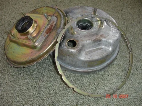
Today I prepped the booster shell halves and connecting ring for painting. From this pix you can see rust just starting to occur. This prepping involved filing off all the sharp edges (mostly from the manufacturing processes) as well as the usual stuff most people do before painting. Silicone coatings are THE BIG ENEMY for spraypainters so I've been careful to remove all traces.
PaintPrep 002.webp

There shouldn't be much to post for reasembly. But it may take time. I've already masked the seals and threads for painting but the wind is blowing a gale. I need good weather for painting now.
PaintPrep 002.webp
 
I've enjoyed your sense of humour in this thread, and I'm very impressed with your attention to detail! I must admit I tend to replace stuff with more well-worn components from a wrecked truck. I'd suggest a vist to a windscreen repair shop to get the rubber boot repaired. I've seen some pretty magic rubber repairs from those guys. You're not down the West Coast with all that rain are you?
 
I've enjoyed your sense of humour in this thread, and I'm very impressed with your attention to detail! I must admit I tend to replace stuff with more well-worn components from a wrecked truck. I'd suggest a vist to a windscreen repair shop to get the rubber boot repaired. I've seen some pretty magic rubber repairs from those guys. You're not down the West Coast with all that rain are you?

"Blowing a gale" is a hint to where I am Muddy. (- The windy capital city!) No doubt the earlier pix of Picton made you think I was on the "mainland".

Thanks for the suggestion. - May just resort to taping that split though. - Or I could try XXXXX on it. (That stuff is amazing but this task would be "pushing it" I think.)

Any repair that restricts movement (and it's hard to think of one that won't) will just promote splitting elsewhere because the rubber is obviously past its "use by" date.

The engine and assoc. stuff from my BJ40 were also used in "Diahatsu Delta" and "Toyota Dyna" light trucks. So when I'm passing by "commercial vehicle wrecking yards" in the future I may enquire about their boosters.

:cheers:
 
Last edited:
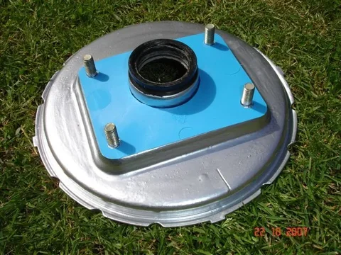
The outside of the shell-halves are now painted and I've cut some gaskets for MasterCyl-to-Booster (black) and Booster-to-Firewall (blue).
The first originally had a paper gasket and the second never had any.
Painted 001.webp

Painted 002.webp
I've made the gaskets out of plastic. My thinking is that their main purpose will be just to prevent the new paint on the mating components from "bonding together" after assembly.
The plastic comes from icecream containers. I'm lucky that the local icecream manufacturer uses "Toyota Sky Blue 854" quite a bit.
(One of the sacrifices I must make is to eat icecream in order to make gaskets.)
Icecream.webp
Painted 001.webp
Painted 002.webp
Icecream.webp
 
One of the troubles with this "as-you-go" type of posting is that you can make a fool of yourself by changing your mind frequently. I can now see that the mastercylinder-to-booster joint is indeed "sealed" . Furthermore, that "drain groove" in the shell is merely there to deceive us.
So any leakage from the main seal on the mastercylinder will certainly feed the leaking brake fluid into the booster rather than onto the firewall. I say this because there is a rubber seal on the end of the m/cyl (that I overlooked) which seals into the recess on booster shell. (See photo.) You can see that the seal lip has the word "UP" at the top with a notch there too. (I admit the notch may affect how well it seals but NO -- I'M NOT GOING TO CHANGE MY MIND AGAIN.)
MCylSeal.webp
A benefit of sealing here is that the "weakest-link seal" (the one that seals on the mastercylinder pushrod) now has a full back-up in preventing air from entering the booster via this path (as I had originally assumed).
But that "weakest-link seal" is still well-engineered as you can see from these pix showing both sides of it:
[/ATTACH]
MCylSeal.webp
PRodSeal1.webp
PRodSeal2.webp
 
Booster reassembly work is going well so it is a shame to have to take a break from it right now to post up this progress report.

I admit the work will appear slow to you but then I do have a full-time job and other chores/interests to take care of. I also had to wait till the day before yesterday (the Tuesday after a "public holiday weekend") to obtain the only new part I'm going to fit - A new O-ring (13 x 2N70)
(Sorry for the blurred photo of it)
Oring.webp

I decided to use my Silicone grease even though it is "clear" and "much more fluid" than the stuff I saw inside the booster on disassembly (which looks similar to White petroleum jelly - But it certainly wouldn't be that).

Interestingly, when I have asked a number of Brake Specialists what they use - They have all been very "cagey". I believe they simply use Silicone Spray (but I wanted something longer lasting).

I have long known that natural rubber is harmed by petroleum-based products but have been confused about the situation with synthetic (man-made) rubbers. I sort-of thought that it would be easy to make synthetic rubber resistant to petroleum products while still possessing the other properties design engineers want. But this is obviously not the case. There are plenty of synthetic rubbers that are easily harmed by ordinary oil and grease. For instance EPDM and SBR types of synthetic rubber are used in the cups/seals inside brake cylinders and they are readily damaged by standard oils and standard grease. I am assuming the diaphragm is made of similar easily-damaged synthetic rubber (but I know the new O-ring I installed isn't).
Here is a picture of the push-rod/air-valve assembly "after cleaning", "prior to silicone-grease-lubrication" and "prior to O-ring fitting":
RodAssy.webp
The rod/valve assembly has a ball-joint inside the air-valve part to allow the rod to bend slightly. This is necessary because the clevis pin actually travels in an "arc" rather than "in a straight line" when you put your foot on the brake.
Note also that the rod is "solid" under compression forces so "booster-failure" should never be able to stop the brakes from working on all four wheels when you depress the brake pedal. (The only booster-faults that I can imagine would cause either "lack of boost" or "brakes sticking on".) (I think that only with "crazy PO workmanship" -or similar -could anything else occur.)
Oring.webp
RodAssy.webp
 
The air valve "seat" is inside the plastic sleeve on the "moving-plate" to which the diaphragm is attached. There are ports in this moving component that allow air to flow onto the fire-wall-side of the diaphragm/moving-plate. In doing this, the air pressure boosts your pedal pressure (against the outer piston of the mastercylinder). Different ports also release this pressure to the other side of the diaphragm when you take your foot off the brake.
Port1.webp

Ports.webp

Here is a picture of the diaphragm/plate assembly with the diaphragm liberally coated with silicone grease.
(Yes. It is on the kitchen table! Lucky my wife will never read this post!)
Lubed Dia.webp
Port1.webp
Ports.webp
Lubed Dia.webp
 
When I showed off the plywood SST I made for clamping together the booster halves, I'm sure I heard some "snickering" and "tee heeing" in the background!

YES. DAMN THING WAS TOO WEAK TO SQUASH THE RIM OF THE DIAPHRAGM SUFFICIENTLY DURING REASSEMBLY FOR ME TO TURN THE LOCKING RING. But never fear - Here's what I used for assistance:
Assistance.webp

Painting the ring and the outside of the shell halves would have made it more difficult for me to turn the locking ring but I figured that the extra paint thicknesses would help in obtaining an air-tight seal (by leaving additional clamping pressure) -bearing in mind that it is not a new diaphragm.

Well now it is back to the reassembly task (Well - With what little time I have left before I need to get ready for work anyway.)
Assistance.webp
 
Something funny is going on. Perhaps I've got too "verbose" for the ih8mud administrators? (Ended up losing 2 posts and getting one repeated - All at the instant I clicked "submit post". Ah well.)

I've decided to continue posting here rather than "getting back to booster assembly" because I have so little time. (Even less now.)

Here's a picture of the two shells together just to prove that I did indeed manage to turn that connector ring:
Together.webp

Quite a while back I got to thinking about the use of alternator-driven vacuum pumps on old Toyota diesels like mine. (Of course an FJ40 doesn't have such a vacuum pump and uses the traditional booster-vacuum-source of "the intake-manifold".) I've heard people say the pump is there because "these diesels can't produce intake manifold vacuum". This statement has always confused me and I don't think it is true!

My diesel engine has pistons and valves that suck in air. It also has a butterfly valve in the intake manifold. And a good vacuum must be produced downstream of that valve when I take my foot off my accelerator because that pedal movement closes it almost completely (exactly as happens in an old-school carbureter-equipped petrol engine).

I believe the Toyota engineers chose the vacuum pump because of safety concerns that arose because of the way my injector pump was controlled.

Imagine I'm driving my BJ40 over rocks on a cliff edge and the vacuum hose to my booster breaks. With the vacuum source being a vacuum pump (as at present), an alarm would go off to warn me of "low vacuum" and I'd usually be able to stop safely enough. There could be no effect on engine power output.

However, if the vacuum source were to be my inlet manifold, this event would reduce my braking ability AND simultaneously power-up my engine. I say this because old Toyota diesels such as mine use a fairly unusual method of "fuel control" whereby, instead of being controlled directly from the accelerator pedal - as most diesels are, fuel delivery is controlled by a leather diaphragm that moves in response to changing pressures/air-flows in the inlet manifold. So the broken booster hose would make my engine "think" my foot is down on the accelerator, and would therefore supply more fuel. And a diesel engine's power output is almost completely dependant on fuel delivery (with the "air-fuel ratio" being largely irrelevant in this respect). ......Hence - Newspaper report reads : "Fourwheel drive accelerates over a cliff while the driver was apparently frantically trying to stop".......... Not good!!!!

Don't believe me? Then try this (if you dare)...........There is still danger remaining in these vehicles (even with the factory's "vacuum pump solution"):

Start up your B, 2B, 3B, H, or 2H diesel engine and leave it idling. Then simply detach the vacuum hose from the rear of your injector pump governor housing. Then watch in horror as your engine speed leaps instantly from "idling" to "its revv limit". (So that hose MUST be well-secured. Although there is little risk of it coming off by itself unless you're one of those people who have fitted a turbo which raises the pressure inside it to above-atmospheric levels!)

Worth thinking about!
Together.webp
 
Last edited:
How about visiting a junk yard with the torn boot in hand to see what you can find? I bet that size boot is actually common on Toyota vehicles.

Good write up so far...

Good idea Coolerman. I think I'll do that. (I'll be looking for one off a newish vehicle so the rubber will have plenty of life left.)
 

Users who are viewing this thread

Back
Top Bottom