Navigation
Install the app
How to install the app on iOS
Follow along with the video below to see how to install our site as a web app on your home screen.
Note: This feature may not be available in some browsers.
More options
Style variation
You are using an out of date browser. It may not display this or other websites correctly.
You should upgrade or use an alternative browser.
You should upgrade or use an alternative browser.
Decision Time - Am I Ready For A Frame Off Restoration
- Thread starter TCSTARK
- Start date
This site may earn a commission from merchant affiliate
links, including eBay, Amazon, Skimlinks, and others.
More options
Who Replied?TCSTARK
Master Debater & Cunning Linguist
- Thread starter
- #302
Game plan...
I had a local mechanic who repaired my brother's mustang come over for a house call. We came up with a master plan and a list of items for me to accomplish before we wire up the engine.
1. Complete the brake lines in the engine compartment. The FSM shows that i need parts #35, #36 and #60. I have built my own lines before bit I am seriously contemplating buying the few missing pieces from SOR for a cleaner look. I also need to get the parking brake installed.
2. Complete the plumbing of the clutch master cylinder to slave cylinder. The slave cylinder is mounted to the driver's side of the AA bell housing!so I will need to research options. I know I can swap out a low profile centerforce pressure plate and run the OEM slave in it's original location (thanks Georg). This may be one of the things I leverage the mechanic's guidance.
3. Run fuel lines, pre-filter, fuel pump and filter to TBI. I need to decide how I am going to set up the auxiliary tank so I can design the return lines, etc. I will drop the aux tank to determine if it has a sender or not. That will help the decision making process. Regardless, both tanks will be cleaned and sealed.
4. Mock up the power steering set up. This will be straight forward since everything was pulled from BIg Blue. I would hate to run a spud shaft for clearance issues but I also hate the alternative of expanding the hole in the front crossmember. I have some time to contemplate this decision.
So, I have plenty to do before the next list of action items is committed to. In the meantime I am installing all of the interior firewall gear. Time to figure out the accelerator redial.
TCSTARK
Master Debater & Cunning Linguist
- Thread starter
- #303
So,.. I was at work surfing eBay for parts. What? Who doesn't.. I came across a picture of an emergency brake assembly and then I had an 'ah hah' moment. I remember seeing a cable in my Chevy box that may be an emergency brake cable that I could use. As it turns out it measures 71" and will be a perfect fit for my NV4500 transmission set up. I installed the hand lever and parking brake assembly. Tomorrow I will tackle setting up the cable/drum set up
windshield looks like it doesn't have the spacers/bolts to hold it at the right angle. Should be fine once you get those in there.
X2 on needing a steeper windshield angle
TCSTARK
Master Debater & Cunning Linguist
- Thread starter
- #305
X2 on needing a steeper windshield angle
I knew the windshield hinges were only bolted on so the rig could be shipped to GA. When I read AntFJ's response I knew immediately he was spot on. Once I get the proper bolts in place the windshield angle should correct the issue.
Now that I know the bows are complete and the top fits, I will wait until I have everything bolted on properly before I install the twists and footman loops.
Tonight I will be tackling the emergency brake cable install. I found this in the tech section and will be using it as my guide: http://www.ih8mud.com/tech/e-brake.php
I will snap some pics during the process.
shipmag
Hagler Technology LLC. Aka Shipmag
I knew the windshield hinges were only bolted on so the rig could be shipped to GA. When I read AntFJ's response I knew immediately he was spot on. Once I get the proper bolts in place the windshield angle should correct the issue.
Now that I know the bows are complete and the top fits, I will wait until I have everything bolted on properly before I install the twists and footman loops.
Tonight I will be tackling the emergency brake cable install. I found this in the tech section and will be using it as my guide: http://www.ih8mud.com/tech/e-brake.php
I will snap some pics during the process.
That reference to the em brake thread was great i will have trouble putting mine back together after 7 years i dont even know where all the parts are. Keep up the good work.
TCSTARK
Master Debater & Cunning Linguist
- Thread starter
- #308
I agree, that link shaved off a decent amount of time that I would have had to stare at the parts to understand how it comes apart and gets put back together.
I tested the parking brake and it seems to work as advertised. I am know researching what type of sealant to put in the splines when I bolt up the drum. Speaking of which, I placed my first SOR order today,...ouch, for a complete set of drive shaft bolts. $50 later... Once I get them I will permanently bolt up the parking drum and reinstall the drive shafts. I have a feeling I will need to modify the length. We sha'll see.
On deck for tonight's one task list is to drop the auxiliary tank and check it out. I will be using Gainesville Radiator to dip and seal both tanks.
So far, I have the following parts in transit. Replacement brake lines for the engine compartment for the brake master and clutch master where they adjoin the T.
Drive shaft bolts to finish up the driveline.
Howell Harness, fuel pump, filter and install manual.
Cruiser corps... Early door paddles, grommets of assorted part numbers, windshield blades, gas caps, etc heading to GA.
I need to pick up some GM hard fuel lines and fuel injection soft fuel lines and whatever else is needed for the auxiliary tank fuel source.
One step at a time...
Last edited:
TCSTARK
Master Debater & Cunning Linguist
- Thread starter
- #309
The auxiliary tank has been pulled and as I suspected it does not have a sending unit installed. This helps the decision making process. I will use the OEM pump and filter to fill the primary tank since I have the parts on hand. I will read up on this type of configuration to make sure I get it right. The tanks have been loaded and will be dropped off tomorrow for cleaning and sealing.


TCSTARK
Master Debater & Cunning Linguist
- Thread starter
- #310
While waiting for parts to come rolling in and the gas tanks to be finished up I started looking at the throttle linkage and how the gas pedal will be installed. It looks like I will need to convert to an older pedal or purchase a conversion kit to change the mechanical linkage to a cable linkage. After reading up on this I went with Downy's cable conversion on eBay under tojoproducts. Yet another item to wait on.
Tomorrow I will be heading down to Waverly Hall GA to pick up some OEM brake lines.
Tomorrow I will be heading down to Waverly Hall GA to pick up some OEM brake lines.
Tomorrow I will be heading down to Waverly Hall GA to pick up some OEM brake lines.
What time tomorrow? Waverly is 25 minutes for me...could take the paint off of your hands.
TCSTARK
Master Debater & Cunning Linguist
- Thread starter
- #314
I worked on the throttle cable modification today and I came up with a great solution... I used the pedal from the Downey throttle cable kit and the stock chevy throttle cable. This required that I drill a square hole in the firewall so I used a 3/8 drill bit and then filed it until I had a perfectly square (more of a rectangle) opening that allowed the stock cable to snap into place.
I had to shorten the cable so I snipped it to the desired length (by desired I mean guess). A quick trip to the hardware store to get a stopper and retaking clip for the cable and I was in business. I bolted up the throttle body and test fitted the cable. Perfect fit.
Pics below:
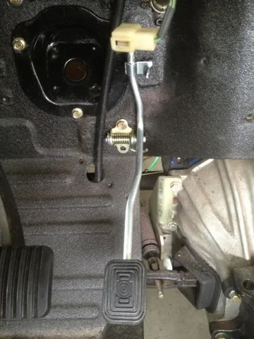
Downey pedal assembly.

Throttle cable in firewall.
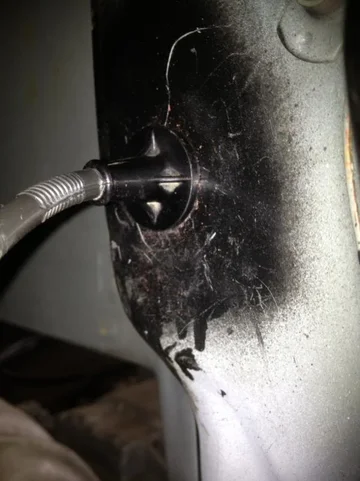
Throttle cable exiting the firewall.
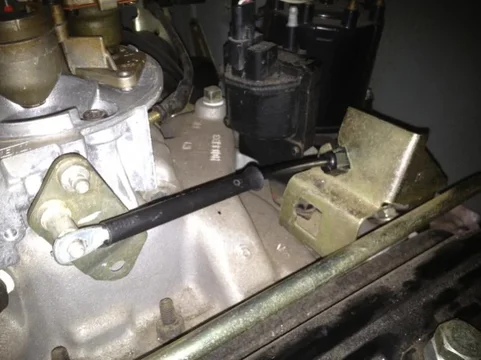
Throttle cable bracket and attachment point to throttle body.
Overall, I am very happy that I was able to utilize the stock cable, bracket and attachment to the throttle body.


I had to shorten the cable so I snipped it to the desired length (by desired I mean guess). A quick trip to the hardware store to get a stopper and retaking clip for the cable and I was in business. I bolted up the throttle body and test fitted the cable. Perfect fit.
Pics below:

Downey pedal assembly.

Throttle cable in firewall.

Throttle cable exiting the firewall.

Throttle cable bracket and attachment point to throttle body.
Overall, I am very happy that I was able to utilize the stock cable, bracket and attachment to the throttle body.
Last edited:
TCSTARK
Master Debater & Cunning Linguist
- Thread starter
- #315
I picked up the gas tanks today. The primary tank was in good shape and all it needed was a steam clean and some paint. The auxiliary tank was dipped, stripped, lined and painted.
I got the auxiliary tank mounted and ready for plumbing. I may regret doing it in this order but 'it is what it is' as they say.
No pre installation pics but here it is mounted back in place.


I got the auxiliary tank mounted and ready for plumbing. I may regret doing it in this order but 'it is what it is' as they say.
No pre installation pics but here it is mounted back in place.
TCSTARK
Master Debater & Cunning Linguist
- Thread starter
- #317
Here is a pic of the refurbished primary tank. It is a shame to put the cover on it and hide it.
So,.. On today's schedule is the following:
1. Review the emergency brake set up to determine why it no longer functions after installing the brake drum.
2. Take some measurements of the driveshaft lengths I will need. It appears that the front will have to be lengthened and the rear will have to be shortened.
3. Start thinking through the auxiliary tank fuel set up.
TCSTARK
Master Debater & Cunning Linguist
- Thread starter
- #318
Today's work
I continued working on the fuel line plumbing. I went back and found a return line access to the top of the tank so now I wall have a fuel inlet (without a 'T' connection for a return), breather, vent and fuel out line.
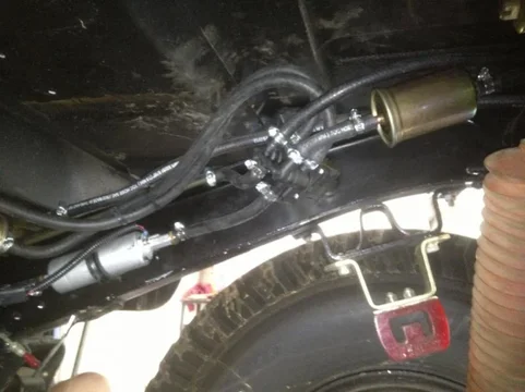
The auxiliary tank will be 'T'd' into the primary tank's evaporator system and will have a fuel filter prior to the pollack 6 port fuel selector switch then pass through the electric fuel pump. I mocked up the fuel pump in the rear passenger frame rail so it will have close proximity to both tanks.
The primary tank has it's own pre-filter and then routes to the rear where it meets up with the switch and fuel pump. The soft lines are then converted to hard lines that run up the frame rail and come out at the engine firewall.
That's as far as I got today.i tried to keep it neat and clean.
Last edited:
TCSTARK
Master Debater & Cunning Linguist
- Thread starter
- #319
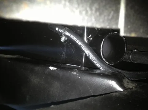
Vent line on auxiliary tank - soft line routed along frame rail and then converted to hard line where it enters the tub.

Fuel line on auxiliary tank running along cram rail to fuel filter, switch and then electric pump.

Auxiliary hard vent line entering tub.

Auxiliary soft vent line 'T''d into evaporator unit.

Primary tank fuel line/return lines routed through tub. I need to replace the grommet since it was too dried out to reuse.

Primary tank soft lines. The fuel line runs to a fuel filter, then along the frame rail to the switch and then back through the electric fuel pump.

This is the location of the pollack 6 port fuel switch.

Hard lines along the cram rail to the engine firewall.

Where the hard lines enter the engine compartment. I am questioning the bend of the fuel line as it may restrict gas flow. I may have to revisit this.
Similar threads
Users who are viewing this thread
Total: 1 (members: 0, guests: 1)


