Ammeter/fusible-links ......late model 40-series

This site may earn a commission from merchant affiliate
links, including eBay, Amazon, Skimlinks, and others.

.... is it not also true that one must actually test the circuit to be sure that the voltage is significantly reduced.

Your right Pete. For curiosity's sake at least, I probably should have selected a link sizing that made my ammeter function and then tried taking measurements to discover the actual voltage reductions for various situations like
  1. Engine off but heater fan running, wipers running & headlights on,
  2. Engine off and turning the key to start
  3. Engine running with a relatively-flat battery (which would have the voltage drop in the opposite direction of course)

Or easier still .... I could have just taken these measurements when my original frayed link was there (and was providing good ammeter needle-deflections).

But then I think if I'd done this I'd probably have blown the link (.. if not from the first test ... then from the last one I've listed here)! :D

...Also we must remember that the majority of the current passes thru the fusible link when the engine is off and the alternator is not turning/supplying elec. And at least on my car this means that the only thing that will be getting current solely from the battery thru that fusible link is the starter and edic relay which if not pulling many amps should not cause much of a voltage drop.

Very true again.

But I wouldn't want my fusible link blowing immediately my alternator decides to fail. And knowing my luck such a thing would happen when I'm driving at night in the freezing cold with my heater and wipers going full-bore. And if that link blew in this situation it would immediately leave me stranded without lighting, heat or wipers. (And I believe the beefier fusible link I'm running now makes this sort of result FAR less likely.)

:cheers:

PS. So I guess you've rightly exposed the fact that my decision to abandon the idea of getting my ammeter to function is not as simple as I pretended it to be. :lol:

Edit: I just did some thinking about your choice of fuse size Pete:

...Right now my fusible link is blown and in its place is a 20 fuse as a temporary measure. And I have no problems starting and running my vehicle with just a 20 amp fuse. And as I said once its started current will be supplied by the alternator for the headlights, heater fans etc etc. I do have a spare and I will probably go to a 30 amp just to be o the safe side....

What is the output rating of your alternator? (My 1979 has a 35A alternator.)

I think your fuse should be sized to match your alternator output as a minimum requirement. Because I think you should allow for a dead flat battery absorbing its entire output (without your fuse blowing). So on that basis if I was to replace my link with a fuse I think I'd need one of at least 35A rating.

Or is my thinking flawed here?

(This further shows my reasoning for why I think the fuses/links must be so beefy - for reliability reasons - that their size prevents ammeter sensitivity.)
 
Last edited:
Nope- I think your dead on there Tom. It seems to me that ultimately the most current the link could ever see (not including a short) is the draw a dead or low battery would make on the alternator. I plan on replacing the link BTW. The fuse is just what I had on hand when I needed to get back up and running to pick up the kiddo after school.

I'm not sure what the output of my alternator is but I imagine it to be pretty low my modern standards. The link was a similar gauge to yours by the look of it.

In terms of finding a replacement so far I can only find the link in 10cm lengths here in Japan. So I may just give that a try first and see how the ammeter functions as well as test for voltage.

Which leads me to the question- how to test for voltage drop? Say we all agree that the most distress the link will ever see in terms of surviving draw would be to recharge a battery. We would not want the link to be compromised in terms of strength and longevity after doing that work.

Pete
 
So I believe "the ideal link sizing for good ammeter movement" WILL cause significant voltage reduction for all downstream loads (like my start relay, glow plug relay, EDIC motor etc). So I've decided I won't go down that path.

Doubling or tripling the resistance of the shunt will have no significant effect on the voltage drop across the shunt, since the shunt resistance is so low: something like 0.001 ohm.

Besides, you can also tap into the copper wire upstream from the fusible link and not alter the overall resistance of the main power feed wire at all.
 
Doubling or tripling the resistance of the shunt will have no significant effect on the voltage drop across the shunt, since the shunt resistance is so low: something like 0.001 ohm.

So you think these ammeters work off millivolts rather than volts Charlie?

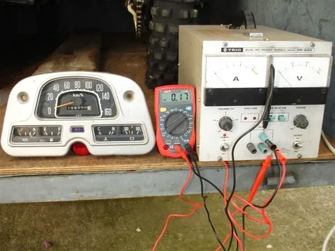
Well it looks like I'll have to run some tests using the "variable DC voltage supply I have in my garage" to see what voltage they do need in reality.

(Remember that my ammeter gave good readings only when my fusible link was "hanging on by one or two strands". So I'd imagine it then had "one hell of an increase in resistance" compared to its original/undamaged state!)

...Besides, you can also tap into the copper wire upstream from the fusible link and not alter the overall resistance of the main power feed wire at all.

You've lost me :frown:.

If you bypass your "monitored fusible link" with any of your circuits then your ammeter can't possibly be expected to give you any idea of the current flow through those circuits.

:cheers:
 
The meters run off milliamps. It is a parallel resistor problem: The flow through the meter vs the shunt is proportional to their conductivities (the reciprocal of the resistance). So if the meter resistance is 1 ohm and the shunt is .001 ohm, the shunt is passing 1000 x the current as the meter.

As you increase the shunt resistance, more current flows through the meter. You can change the shunt resistance by making the distance between the meter leads longer without changing the total resistance in the power feed wire. For example, one lead is attached to the battery side of the shunt and the other end is 1 meter up the white wire just before it enters the firewall. That way the total shunt resistance is that of the fusible link + 1 meter of 10 ga copper wire. I'm guessing that this will double or triple the meter sensitivity. If you had a known current flowing in the wire, you could adjust the distance to match the meter reading.
 
My meter was melted because someone decided to put 10a fuses in the leads to the meter. However the fusible link was still operational- barely. So I'm sure my meter was showing some reading before it melted! And it should have told the owner to check that link- but they didn't know about the system.

If spreading the leads further apart- or using a smaller gauge fusible link (wonder what the actual difference is between metric and commonly used AWG wires used as replacements) would affect the sensibility of the meter- it would also throw off the measurement relative to the 50 amps listed on the gauge- not that it is that big of a deal.
 
.... You can change the shunt resistance by making the distance between the meter leads longer without changing the total resistance in the power feed wire. For example, one lead is attached to the battery side of the shunt and the other end is 1 meter up the white wire just before it enters the firewall. That way the total shunt resistance is that of the fusible link + 1 meter of 10 ga copper wire. I'm guessing that this will double or triple the meter sensitivity. If you had a known current flowing in the wire, you could adjust the distance to match the meter reading.

Ahhhh. I think the penny has finally dropped Charlie! (I can be very slow on the uptake at times.)

So you're suggesting using part of the loom wiring to extend the "monitored resistance" beyond just the fusible link? (ie. You're suggesting moving the connection-points feeding the twin-fuses further away from the ends of the link?)

I think that would only work if that "loom wire" had the same cross-sectional area as the link wire (or less) .... but unfortunately it hasn't. It is significantly larger to ensure that "the link wire" melts in preference to "the loom wire" in the event of "short-circuit-current". And because it is larger it must actually contribute FAR less to voltage drop (in comparison to the same length of link wire).

BTW .... You were right about the "meter driving voltage" being milli-volts rather than volts. (I was wrong!)

This test I did just now shows that 170 millivolts causes a "half-deflection" (25 ampere reading).

Ammeter0.3Vfullscale.webp

Similarly 300 millivolts causes a full-scale deflection.

(I tried the tests with reverse polarity too ...achieving identical results in the other direction..... as one would expect.)

So this experiment proves how wrong I was to list "avoiding reduction of downstream voltages" as my key reason for needing the monitored fusible link to be so beefy (so that it has the unfortunate side-effect of preventing proper ammeter movement). In fact this experiment shows it was a COMPLETELY INVALID REASON (because a full-scale deflection would only reduce downstream voltage by 0.3V .... which is insignicant!)


My meter was melted because someone decided to put 10a fuses in the leads to the meter. However the fusible link was still operational- barely. So I'm sure my meter was showing some reading before it melted! And it should have told the owner to check that link- but they didn't know about the system.

If spreading the leads further apart- or using a smaller gauge fusible link (wonder what the actual difference is between metric and commonly used AWG wires used as replacements) would affect the sensibility of the meter- it would also throw off the measurement relative to the 50 amps listed on the gauge- not that it is that big of a deal.

Yes. I doubt "reading accuracy" was something the designer aimed for Pete.


So anyway.... at this point.....I still think these ammeters can't be made to register properly/usefully. But my key reason now .. is that the monitored fusible link must be sized on the maximum alternator output assuming this high current could all flow through the link when the engine is jump-started with a dead-flat battery. ............ And when the link is sized this way, I believe normal charge/discharge currents are too insignifcant in comparison. And therefore I believe they won't produce enough voltage drop through the monitored link to get the ammeter to register .

:cheers:

PS. The early-type ammeters (without shunt resistors/fusible-links) surely faced (and overcame) similar sensitivity issues. ie. They had to be able to accept high currents while still registering smaller ones. (I understand owners of these early cruisers say their meters perform well!!!)

So perhaps the problem is simply "poor ammeter design" in the later models.

I think the ammeter sensitivity/movement needs to be "disproportionate". ie I think the needle needs to move more easily with changes in "low current" compared to changes in "high current".

And in support of this "poor ammeter design theory" - I did notice the needle movement to be appear "stiff" when I was applying voltage to it. (It moved in jerks rather than smoothly ... and I don't think it was my power supply at fault.)
Ammeter0.3Vfullscale.webp
 
Last edited:
The loom wire has significant resistance. Even though it may be larger diameter, it is much longer than the fusible link. The voltage drop across the shunt depends on the current, so you could also increase the lenght of the fusible link to get the meter sensitivity dialed in with no negative effects when the battery is charged and negligible current is flowing.

The older style meters have a shunt built into the meter, so they are called "internal shunt" style meters.

Maybe your meter needs to be cleaned so it moves freely.
 
Slightly different course here- but would the ammeter still work across a fuse as opposed to a fusible link?

pete
 
...Maybe your meter needs to be cleaned so it moves freely.

This ignores the fact that so many owners of late model cruisers never see their ammeter needles do anything other than the odd twitch. (It isn't just me Charlie.)

Also.... I've owned this cruiser since 1981. (It had the same ammeter insensitivity then when surely the ammeter was clean!)

Slightly different course here- but would the ammeter still work across a fuse as opposed to a fusible link?

pete

Put it this way........... You'll be no worse off than me if you use a fuse Pete. (I consider my ammeter as "dead".)

I've abandonned the idea (despite Charlie's helpful advice) of trying to tweak my fusible-link/monitored-resistance to make my ammeter sensitive. (I've fitted a voltmeter so my ammeter is now "just for show".)

If you use a fuse instead of link-wire then you'll have greatly restricted your ability to tweak the resistance of your "monitored-resistance"/shunt. (You are limited to swapping from a 40A fuse to a 35A fuse for instance. That is, unless you try Charlie's trick of extending your "twin-fuse connections" onto the loom.)

Also, I vaguely remember reading that the alloy used in fuses is specially manufactured to exhibit low resistance for current flows below the "blow point". If so, this would inhibit meter-sensitivity.

But as I say .... may ammeter is useless ... so you can't do worse than that! :lol:

:beer:
 
Slightly different course here- but would the ammeter still work across a fuse as opposed to a fusible link?

pete

Yes, although I wouldn't know if accuracy would be affected. But the purpose of the fusible link is different than that of a fuse. Momentary faults do not cause a fusible link to burn. That requires sustained voltage levels that would cause harm (fire) to the wiring loom but not necessarily cause a fuse to blow. Your fuse replacement for the fusible link is probably unwise and not really providing you with any protection that's not already covered by the fuse box.

For anyone still interested in correcting a wiring harness missing its fusible link connector here is the updated posting for the 8mm female spades. Let me know if you buy a 10-pack;)

CRIMP TERMINALS FEMALE SPADE 8MM RECEPTACLE 10 PACK (eBay item 310123138691 end time 08-Dec-10 22:57:10 AEDST) : Cars, Bikes, Boats
 
Lost Marbles, re the bright voltmeter, perhaps you can identify the wire that powers the internal lamp and add in a potentiometer to lower the brightness to an acceptable amount? A resistor would most likely do the same, but it would take some putzing around to find the correct amount of resistance.
 
Lost Marbles, re the bright voltmeter, perhaps you can identify the wire that powers the internal lamp and add in a potentiometer to lower the brightness to an acceptable amount? A resistor would most likely do the same, but it would take some putzing around to find the correct amount of resistance.

Thanks for the suggestion and you're certainly tempting me Blue77FJ40.

I do like "the old-world charm" of having dash-lighting that isn't eye-catching .. And for safetys sake I personally don't like bright lights drawing my attention off the road.

"Superbright LEDs" by themselves have made my OEM cluster easily readable but it is still not what I'd call "bright". (You still need to consciously look in that vicinity.)

Any electronic's people out there able to suggest a "compact poteniometer product" (ie "a compact adjustable voltage dropper") that I can can maybe buy off the Internet to put in my Voltmeter lamp feedwire (and keep hidden behind my dash)?????
 
I would really like to see the results of your moving the Amp Meter leads further apart on the charge wire.

I bought a 100 amp shunt last year. When I get the chance to "play" I want to use it in place of my amp meter. You basically hook a VOLT meter to it then read the volts and do a calculation to see how many amps your pulling. 50mV per amp output. So 1 amp =50mV and 100 amps =5 volts MUCH more resolution than a dash gauge. Even a cheap dash volt meter connected to it permanently would be better than what you have. :D For anyone wanting to play with the shunts they are available from Allied Electronics Part #378-0103 and cost $23.07. www.alliedelec.com

They also have an analog 0-100 amp DC meter designed to go with the above shunt. Part # 378-0011 for $59.97
 
Last edited:
Well isn't the stock late model ammeter essentially a volt meter? If the correctly sized shunt were found it would be a better choice for taking the measurement than the fusible link?


pete
 
Hi there.

It doesn't perform at all really (which is what I've been used to seeing for almost all of the last 30 years). The biggest movement I get is a "microscopic twitch" when I have my hazards on.

In my opinion, if I was to deliberately downsize the "monitored fusible link" to obtain a "functioning/useful ammeter" ... then my cruiser would become unreliable because that fusible link would be at risk of "blowing" under peak loads or when it has suffered minor-deterioration from corrosion/fatigue some time in the future. And probably more importantly - if I downsized that fusible link enough to make my ammeter work properly - I think it would also be dropping the voltage to downsrtream components to unacceptably low levels (causing further "unreliability problems" and damage). Edit: My fear of "dropping voltage to unacceptably low levels" (expressed here) proved to be unfounded when I bench tested a similar ammeter (later in this thread) to reveal that only 0.3V of voltage drop in the fusible link produces a full-scale ammeter-needle-deflection. (However I'm still not prepared to downsize my fusible link.)

In other words ... I think the design of the late-model ammeter system is basically flawed and these ammeters serve no useful purpose.

In fact, I'm almost tempted to fit a "charge light" (but I won't because I prefer to keep my dash looking standard).


Yep

View attachment 418989

Hi Lostmarbles,

Great to read your writeups.

I recently purchased a 1981 BJ43 and loving it. Needs a bit of work especially with the electricals as the wiring harness has been hacked and I don't have any fusible link protection. Can you please help? I have attached a picture with queries to the fusible links you created.

Mine is a 24 volt system and also need help with the proper guage links I will need for the build. Will they be the same as yours?

Apologies for the many questions but I have seen circuit diagrams with 3 fusible links for the year 81 model BJ. Will a similar fusible link as you built be suitable for this third link.

BTW: I live in Sri Lanka and good Auto Electricians over here are a rare breed.

Thanks in advance.
fusiblelink2.webp
 
1981 BJ43 .....wiring harness has been hacked and I don't have any fusible link protection.....Mine is a 24 volt system... and also need help with the proper guage links I will need for the build. Will they be the same as yours?...I have seen circuit diagrams with 3 fusible links for the year 81 model BJ. Will a similar fusible link as you built be suitable for this third link. ....I live in Sri Lanka and good Auto Electricians over here are a rare breed.


Hi there Kev.

I have only two fusible links as you know.

Well the WHITE one goes between my battery's +Ve terminal and my ignition switch. So it protects the main feed that supplies most of the power to my cruiser. (Lights, wipers, blower motor etc). Because of this, it is the one that has the two little wires (B and WL colour codes) tapped off its ends that feed my ammeter.

Here's a wiring diagram I made up that shows how these two fusible links fit in with my starting and preheating systems (which may be helpful for showing you exactly where they sit):
Start&GlowWiring.webp

As you can see, my other fusible link, the BLUE (L - colour code) just protects my preheating and starting circuits.

As for sizing a fusible link, simply choose link-wire that is 2 wire sizes smaller than the wire you're inserting it into:
FusibleLinkData.webp

Here's a pic of those fusible links of mine connected to my battery:
FusibleLinks3.webp

So this is what I get from that:
fusiblelink.webp

I'm not really familiar with 24 volt versions but I do know the wiring diagram, that covers both 12V and 24V versions, shows THREE fusible links. (I've only ever had TWO.)

Here's a wiring diagram for a 1981 BJ43 that shows the three. (Circled.)
1981BJ43.webp

All I can say is, EVERYTHING coming off your 24V +Ve terminal, other than that REALLY THICK cable leading to your starter motor solenoid, should be protected by a fusible link to avoid the risk of vehicle fires. And however many fusible links you need, you can size them (and make them) easily enough yourself because it's not rocket science.

Hope this helps.

:beer:
Start&GlowWiring.webp
FusibleLinkData.webp
FusibleLinks3.webp
fusiblelink.webp
1981BJ43.webp
 
Hi there Kev.

I have only two fusible links as you know.

Well the WHITE one goes between my battery's +Ve terminal and my ignition switch. So it protects the main feed that supplies most of the power to my cruiser. (Lights, wipers, blower motor etc). Because of this, it is the one that has the two little wires (B and WL colour codes) tapped off its ends that feed my ammeter.

Here's a wiring diagram I made up that shows how these two fusible links fit in with my starting and preheating systems (which may be helpful for showing you exactly where they sit):
View attachment 789084

As you can see, my other fusible link, the BLUE (L - colour code) just protects my preheating and starting circuits.

As for sizing a fusible link, simply choose link-wire that is 2 wire sizes smaller than the wire you're inserting it into:
View attachment 789086

Here's a pic of those fusible links of mine connected to my battery:
View attachment 789087

So this is what I get from that:
View attachment 789089

I'm not really familiar with 24 volt versions but I do know the wiring diagram, that covers both 12V and 24V versions, shows THREE fusible links. (I've only ever had TWO.)

Here's a wiring diagram for a 1981 BJ43 that shows the three. (Circled.)
View attachment 789091

All I can say is, EVERYTHING coming off your 24V +Ve terminal, other than that REALLY THICK cable leading to your starter motor solenoid, should be protected by a fusible link to avoid the risk of vehicle fires. And however many fusible links you need, you can size them (and make them) easily enough yourself because it's not rocket science.

Hope this helps.

:beer:

Thanks very much Tom. You are a great help.
 
Excellent-excellent thread! I may have found some of my charging/power problems here. Thank you for posting this-very helpful.----- I love your style of writing
 

Users who are viewing this thread

Back
Top Bottom