Alternator altering (1 Viewer)

This site may earn a commission from merchant affiliate
links, including eBay, Amazon, Skimlinks, and others.

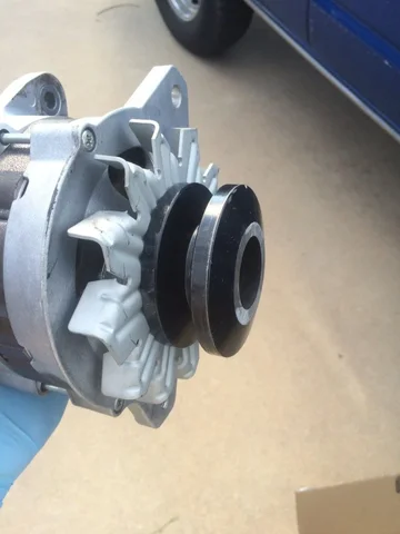
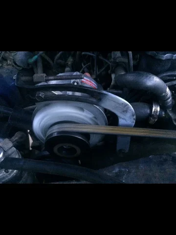
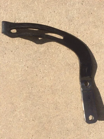
Since this seems to be the main thread on this conversion, I will add my data point. Rock auto came through with a Denso 80 amp alternator, pulled the plug off a 1991 Toyota pickup at the junk yard. Then came the fun part. Extended the tensioner bracket 3" hole to hole. Also pulled the double pulley off and cut the front pulley off then ground it smooth. This allows the pulley to clear the radiator fan with out trimming. The extension on the bracket makes it so you don't have to trim the fins of the alternator fan. Then the search was on for a longer alternator fan belt. After four try's we finally hit the jackpot. image.jpg image.jpg image.jpg image.jpg

image.jpg
 
Thought I would add some notes to the process. Prob. a one banana job, time required about one hour.

Tools required:

Impact wrench
21mm impact socket (removing pulley)
Grinder
Various wrenches and sockets for alt bracket / tension-er
Pliers (for butt splices)
Heat gun (if you heat seal your but spliced connections)
Electrical tape

Parts:
3fe alt 80amp (source from rock auto as listed, or used parts)
@Coolerman part# 3P8892W

Started off on the bench here are the 2 alts side by side. The one on the left is the FJ62 3FE 80 amp and the one on the right is the FJ60 2F 60 amp.

#1.JPG


Use the impact and 21mm socket to loosen/remove the pulley wheel nuts. I dropped some penetrating oil on them earlier in the day and didn't have any trouble with removing the nuts quickly.


#2.JPG


With the pulley wheels off you can swap the blades as noted earlier in the thread, or trim the fan blades to allow clearance on the adjusting arm. I don't have access to a welder to lengthen the adjusting arm (also mentioned in the thread) so I was trimming the fan blades.

#3.JPG


This was my first pass at trimming the blades down. I ended up mocking it up with this trim angle and it actually needed to be a steeper angle in order to clear the adjusting arm.

Here the pulleys have been swapped. if you don't switch the pulleys you will need to cut down the double pulley wheel to a single in order to clearance the plastic radiator fan blades. Also mentioned in this thread you can cut the plastic of the rad. fan blades rather than cutting the metal of the pulley. Felt like swapping the original was simple and went that route.

#4.JPG


Next up wiring! Thanks @Coolerman. His part looks like this and comes with 2 butt-splice connectors.
#5.JPG
 
Next up pulling back the three wires connect to the Alt Harness. Sorry for the bad photo below. One wire was white and thicker, one wire whas white/yellow and smaller gauge.
#6.JPG


View attachment 1214339


Spliced and heat shrunk.


#7.JPG


View attachment 1214336

Taped and covered.

IMG_7329 (1).JPG
 
Last edited:
#8.JPG


Alt fan blade clearance , Adjuster is maxed out. Will be sourcing a smaller belt it does turn with out sqeeling but would rather have a bit of adjustment left. To be continued.
 
Thanks @FJ40Jim.

I'm working on the belts. I agree that the one on there is too small. It was the recomended belt from a sag pump swap thread. Definitely looking to beef it up.

I'll post what I end up going with.
 
Thanks for the simple and clear write-up of the path you chose to go. It is great to have option when a guy is contemplating a mod.
This one is definitely in my future.
 
Thanks for putting all this together, guys! Is the 62's 90amp, internal fan version viable (i.e. Remy 14958 or Denso 2100177 at Rock Auto)? @NookShneer , does the bracket lay a little across the face of the 62 alternator? If so, the internal fan version wouldn't work unless you extended the bracket, a la @TX_TLC , so that it clears the body, right? TX_TLC, does the alternator actually adjust within your extended bracket still? Does the top bolt of the alternator travel along the path of the slot still, since that 3" extension changes the angle?
 
60tex, I haven't tried the 3FE 90A version, but the rockauto pics make it look like they are swappable with the 3FE 80A version, which as we know is sorta swappable from the 2F 60A version. When I first tried this, I bought a used FJ62 JY alt for $40 for sizing. Once it was all together and running for a while, a new looking reman was sourced off Rockauto.
 
the 80 series alt should drop right in in place of a 62 series alt...
 
Part# 3P8892W

Link
Think you meant this link..
Cruiser Wiring

Nevermind... site does not allow you to link sections... Go to ALTERNATOR CONNECTORS on the menu on the left. Part is about 1/4 way down the page. Not bad for $14. Something to add to the list of mods for down the road.
 
Last edited:
Thanks guys. I picked up the 80A version, and the 90A version is on special order from O'reilly. Going to see which one would work - preference for the 90A version to allow for more flexibility on future add-ons.

So here's the plan:

Currently, the way I understand the setup is that the thicker white wire goes between the battery through the fusible link to a crimped ring connector at the alternator for charging. A thinner white wire also comes off of the ring connector to go into the harness to power the taillights, instrument lights, brake lights, etc. As I'm a little worried about a potential 90A going through a fusible link that's built for 40-60A, I'm going to run a thicker cable with an inline fuse directly from the alternator to the battery. Then, I'm going to tie straight from the back side of the fusible link into the body harness (without meeting up at the alternator), so that the body harness still is protected by the fusible link (plus all the normal fuses under the dash), and factory wiring never sees 90A.

Any reasons why this wouldn't work, or better ideas?
Should I spec a 90 or 100A fuse for the inline fuse in the charging wire between the alternator and battery?

I went ahead and did a 150a fuse for mine after recommendation from @Fourrunner when using his upgraded cables. Depending on what you add will probably determine how much you should go. Since you are doing just standard stuff right now the 100A should be just fine and then if you start adding more you can always upgrade the fuse.
 
Thanks guys. I picked up the 80A version, and the 90A version is on special order from O'reilly. Going to see which one would work - preference for the 90A version to allow for more flexibility on future add-ons.

So here's the plan:

Currently, the way I understand the setup is that the thicker white wire goes between the battery through the fusible link to a crimped ring connector at the alternator for charging. A thinner white wire also comes off of the ring connector to go into the harness to power the taillights, instrument lights, brake lights, etc. As I'm a little worried about a potential 90A going through a fusible link that's built for 40-60A, I'm going to run a thicker cable with an inline fuse directly from the alternator to the battery. Then, I'm going to tie straight from the back side of the fusible link into the body harness (without meeting up at the alternator), so that the body harness still is protected by the fusible link (plus all the normal fuses under the dash), and factory wiring never sees 90A.

Any reasons why this wouldn't work, or better ideas?
Should I spec a 90 or 100A fuse for the inline fuse in the charging wire between the alternator and battery?


Generally Fuse to 20-25% over peak amperage. So I'd do 120. Your going to have a fuse block of some sort for that amount of amperage. You could also look at circuit breaker.

For the lowest cost and cleanest install. I'd look at terminal style fuse blocks. I'm thinking I'd change my direct wiring to that style for a cleaner install.
 

Users who are viewing this thread

Back
Top Bottom