Builds 86 Xtra Cab Build (4Wheelunderground 3 link front, 4 link rear and 3.4 swap) (2 Viewers)

This site may earn a commission from merchant affiliate
links, including eBay, Amazon, Skimlinks, and others.

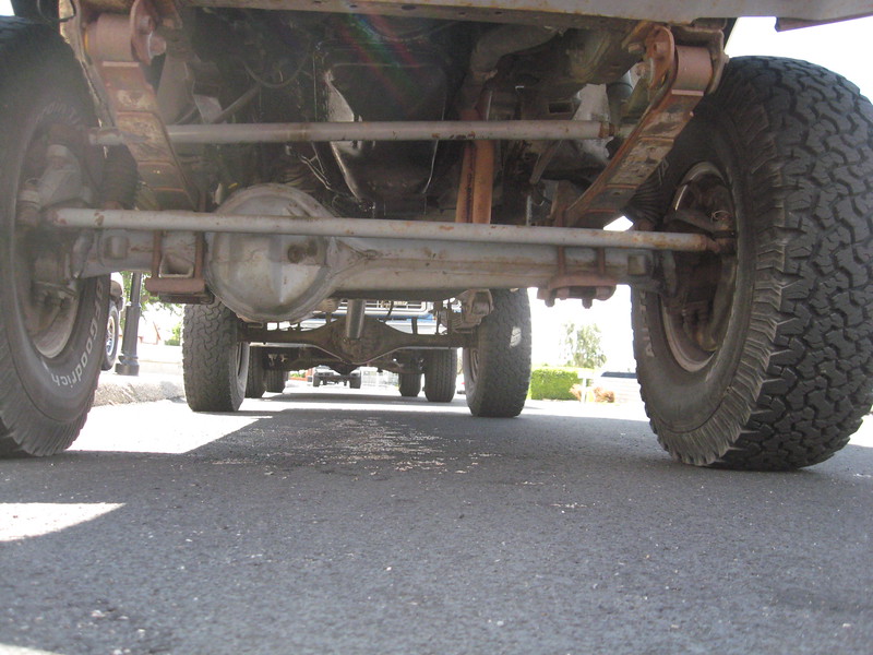
Ok, I'm back. I decided to get back on the front end. It helps to have it in place so I have good points to measure from when I get back to setting up the rear.

I pulled the front axle out so I could finish welding it up. After welding I went over all the sharp edges with my die grinder.

IMG_20221215_152903030.webp


IMG_20221215_152937353.webp


IMG_20221215_152838879.webp
 
Tomorrow I'm hoping to pull the knuckles and spindles off the 88 so I can get them on this axle. I wish I had another set of high steer arms so I can leave the 88 a roller.

Once I get the knuckles setup and the tie rod on, I'm going to see about fabricating a truss/brace that I can incorporate with my hydro assist cylinder mount.
 
We use what we have, but if you can find your way to owning one of these: B000REJM3K I find it to be amazing for deburring things. I run a worn 100 grit belt on mine almost exclusively. I came about it used for a lot less than the amazon price and it's likely the most used power tool in my shop. Everything gets deburred by it before any assembly happens.
 
Good idea. I actually have a belt sander and I also use the heck out of it. I just didn't think of putting all these brackets on it before I tacked them on. These laser cut brackets are really sharp.

I forgot to mention that I'm also scrounging up parts to mount some bigger brakes up front. I have the 14WA calipers, rotors and some longer wheel studs on the way. I need to measure the rotors ID so I can turn my IFS hubs down while everything is apart and clean.

@cruisermatt had some good information on the brake swap in another post and was quick to answer my questions.

@4runner2FJ60 was nice enough to post up information he found on the longer wheel studs on that same brake swap thread as well.

The brakes might not happen till after Christmas. I will still plug away at the axle assembly and mods to mount the steering ram though.
 
Last edited:
Don't I know the "aw shoot!!! I forgot to deburr those..... " all too well!
Since I've started modeling my own brackets etc and having sendcutsend.com cut them out I've been using the the sander even more than I used to.

Can you please link the brake thread? At one time I scoured the net looking for longer wheel studs and didn't find any. Modeled what was needed and got a quote from ARP for 100 sets of them (smallest volume that made a set reasonably priced), but couldn't get enough interest at the time to make that project go.
I've also messed around with reverse engineering from the knuckle out with the idea of designing a big rotor conversion. (My first job out of school was designing that sort of thing for wilwood.)
 
Thanks gnob, I saw that and also saw a thread mentioning that the rotors will be hub centric so make sure to measure before machining. When it say's to turn them to "about" 6.680 I thought that I better wait until I have rotors in hand. Did your rotors fit ok at 6.680?

ntsqd, I didn't put the link up because it was from I think a 60 series thread and I'm building a mini truck. It had some good info I was looking for so I'll post the link. Page 8 had some good info from cruisermatt and the wheel stud chart as well.

 
I made a cardboard template of the frame rail from the core support mount to the first cab mount.

Originally I was going to plate inside, outside, top and bottom with 3/16" steel. I emailed Brian @ 4Wheel Underground and he said to plate outside of both rails and all 4 sides on driver side only.

I cut out the piece, clamped it to the frame and traced EXACT fit to the frame. Used my belt grinder to trim as needed. Then I just copied it for the other side.

The belt sander attachment on my bench grinder is the best tool I never knew I needed. I use the heck out of it.

View attachment 2718523

View attachment 2718524

View attachment 2718526
Where did you get the belt sander attachment?
 
I got it a while back. I think it's called Multi Tool belt grinder attachment. It's from Australia. I just googled those words and a ton of sites come up. Wow it got a lot more expensive.

I bought it to attach to my existing grinder. I use a wire wheel next to it and I use the hell out of it setup that way. You can buy a complete unit as well. It's very well made, has great customer support. Maybe the most used tool in my garage. I have a really nice grinder with stone wheels as well but this one gets the most use.
 
I managed to get the parts off the 88 and mocked up on this axle housing.

I was thinking of mounting the steering cylinder basically under the tie rod and slightly toward the housing.

The tie rod is furthest out going straight ahead and arcs toward the housing when turning either direction. Looks to be about an inch or so. I didn't measure the distance.

I have an idea of what I want to build but I think I better just tack something on temporarily just to position the cylinder. Then I need to get it back under the truck and cycle the suspension again. The tie rod and pan hard bar were really close to the oil pan. I need to make sure the clamp on the tie rod won't drag across the oil pan.

I'll go back through my build pics too for a better idea of clearances.

I'm also open to suggestions.

IMG_20221216_145007381.webp


IMG_20221216_145020477.webp
 
This set-up is a modified IFS pitman arm (The Sky flat arm put it too high), modified old school "double steering arm" (only ~1" higher than a high steer arm) on the knuckle, 22R on stock mounts in the stock location, stock bump-stops on the modified frame contact points. It hit once, don't know where or when, and put a slight crease in the oil pan. Was it me, I'd get that clamp as far to the driver's side as reasonable.

i-dGd54zp-M.jpg


i-dBxsvxw-L.jpg
 
Yeah, definitely need to stay to the driver side. On the 88 I had to stay center or the ram hit the U-bolts and bump stop on the spring plate.

Here's what I was going to try. EDIT: The rod end will be turned 90 degrees for a double shear bracket that will be welded to the clamp.

Here's full left turn.

IMG_20221216_181558642.jpg
 
Last edited:
I have this back brace for the rear from Ruff Stuff.

Thinking of fabricating something similar for the front and add a mounting point for the cylinder. Also, I need to fab up some knuckle ball gussets.

IMG_20221216_181825778.jpg
 
Last edited:
Holy man... nice frickin work. I saw this thread when you first started in on the initial frame work, but somehow missed the year and a half of progress. 3 and 4 link sure looks like a lot of dinking around to get it right. A lot of checking of clearances and postions etc. Lots of fab work even though the "kit" comes stamped out. Links crossed my mind, but I'll stick with leafs for the forseeable future... 10 years minimum, lol.

And as a reply to the driveshaft talk around page 20.... I'll agree with the driveline experts that you wont see the benefit of exact driveline angles and its nothing to worry about. To cite my truck as an example, my T case is pointed down around 6° down which makes the front flange point up 6°. My front shaft has an angle of 8° down. My front pinion is a high pinion, and is 5°. Front shaft is a CV shaft. That makes the relative angles 14 degrees at the CV and 3 degrees at the pinion. I can do 75mph smooth as glass out of the front driveline. Shaft speed of around 3500+ RPM there. Didnt go faster because thats all the 22re can muster, but I bet the shaft would have handled it. And theoretically under load, the front pinion moves away from the shaft which would increase that diff operating angle... on paper the angles dont sound that good, in practice I've had zero vibration.

Same T case set up but with a low pinion, my shaft angle was 13.5 and diff at 5. Which would make the relative CV angle 16.5° and the diff joint angle 8.5°. I got the slightest buzzing/humming vibration at 55mph out of the front shaft. Before 55, you wouldnt have been able to tell the hubs were in. Theory on paper that should have rattled my fillings out pulling out of the driveway.

My rear shaft was a single joint at both ends, 10° pinion. 12° shaft angle. Relative operating angles were 6° at the T case and 2° at the diff. Smooth as glass upto 62mph.
Switched to a CV in the rear as thats what it is set up for, no change. Just as smooth upto 62mph. I've had 4 rear shafts in the truck and cant get it smooth at 63mph+. I reckon I have something else going on there. Took the rear shaft out and thats how I found out the front shaft is good to 75.

Granted my driveshaft is tight with zero play in the slip, spicer life joints, straight to within .003", and balanced.

It is my opinion that the paper theory of U joint operating angles can be fudged with. If its not totally out of whack, the benefit you get from exact angles is U joint life, I.E OEM 200k miles life. The shaft can eat up some degrees and run smooth.
 
Thanks for that drive shaft info. Don't forget, the rear shaft also has an angle to the side slightly. The T case flange is centered but the rear diff flange is not. Maybe you knew that.

I had a slight vibration in the rear shaft develop after years of being smooth. I put new U-joints in, cleaned and greased the splines and I even found a kit to rebuild the CV centering yoke. It still had a vibe so I took it back to the guy that built it. It took him a bit to figure out, but it ended up being an out of spec centering yoke part. I just cut a CV out of another Toyota shaft I had in the shed and he swapped it out. I didn't want to chance another bad kit.

After 4 different shafts probably not your issue. Maybe try a slight pinion angle change? Setting them at 2 degrees down is to compensate for the axle rotating up from torque. Maybe it's rotating over 2 degrees?? Or not rotating? I set mine at zero and put in a anti wrap bar. It was smooth. Kind of like your "on paper" it's not supposed to be at zero but it worked for me. Sounds like you covered everything else.
 
I didnt know that the diff is off center... how much off center? Sometimes I thought when looking at the shaft it looked like it went sideways a bit, but it was so close I couldnt tell if it was an optical illusion somehow. Didnt plumb bob anything.

I would have assumed the diff flange was center to the frame because the axle shafts are the same length and the perches were the same distance from the axle flange ears to the center pin.

Currently my junk is ready to have a new T case mount burnt in(not sure if previous owner had it centered between the frame rail, but I had to cut them off for different reasons) and my rear leaf perches were in rough shape and had a hollow center lift block that etched into the perch in a weird way. Also ready for new perches to be burnt in. Hoping when Im done with that my vibration fixes itself, but we'll see. I havent fully decided where I'm going to set the pinion at. If I had to guess I'd assume the pinion was moving too much beyond the 2 degrees because of the perch and lift block hokey-ness.

Theoretically the single U joint in a CV should operate at 0°. When a ujoint is operating at an angle it speeds up and slows down as it rotates, so ideally you would have a joint at the other end opppsite angle to cancel out eachothers speeding up and slowing down. Because the CV shaft doesnt have another U joint to cancel out the single joint the only way to get a single U joint to run at a constant velocity is to have it at 0°. But mechanically, a joint at 0° doesnt rotate, the needles create flat spots, and the grease doesnt move. With 1° atleast the joint needes are moving and it is pulling grease. But as I've alluded to you can get away with several degrees of non-cancelled out angle.
 
It is normal practice to set the rear pinion UJ down at up to about 2° more angle than at the trans or t/c output. (I've seen 4°, but that seems excessive.) Not as necessary on linkage as it is on leaf springs.

Completely agree with all UJ's needing to operate thru some angle.

I'd mock-up with the hose ends that you plan to use in place on the ram. Those formed tube 90's consume more space than you'd guess and there is no way in hell that I'd ever use a machined 90° hose end in PS plumbing. These systems are bad enough about cavitation, don't need to add more places for it to occur.

I pushed the Easy Button and went with Marlin's knuckle ball gusset kit. Wasn't worth my time to develop something on my own.
 
Last edited:
X2 on the Marlin's Knuckle gusset Kit. I used them as will.
Is there no way to get the ram above the tie rod up out of harms way ?
 

Users who are viewing this thread

Back
Top Bottom