Strange Edic/Fuel Control relay woes: Please help

This site may earn a commission from merchant affiliate
links, including eBay, Amazon, Skimlinks, and others.

Yeah. I sometimes wish I had been more imaginative with my username.

I like names that make it hard for people to take you seriously and that make people puzzle over your choice (and over what sort of person you REALLY are.)

For instance - the person who chose "ratpuke" did well in my books.


Thanks. Nothing really special. It was a nickname from college. People would ask me "Do you think that guy is hot" and I would say "I don't know. I don't care. I guess he's not rat puke or anything like that." So, it stuck. Little did they know that rats can't vomit.

Do You Know Why a Rat Can’t Vomit? | Scienceray
 
I did not get any click at all and my FCR was open so I would have been able to see any movement even if for some reason I could not hear a click. Side note it did click when I accidently touched the Pos(+) to ST :eek:...

The fact that you did not get a click when you earthed the "E" terminal and then (at the same time) applied + 12V to the "IG" terminal ......proves to me that your FCR is really/still faulty Theo. (So I think you are correct to be sourcing another one :clap:.)


..I was not sure if you meant connecting an "additional" Neg(-) or using the existing Neg(-) which was clamped to the E already, so I did both to cover all bases and there was no clicking of any kind......

Jeeez Theo.

And I thought I was being clear in saying "in addition to". :D

I meant for you to leave the existing "negative/earth" on "E" and apply a fresh one to "Oil" ...... AS WELL.


..Once again I was not sure if you meant using an additional(2nd) Pos(+) or just the existing Pos(+) which was already clamped to IG at that stage, so once again I did both and everytime the Pos(+) touched or broke contact with ST there was an immediate click. ...

Ditto (Again - I meant what I said - "in addition to")

But it sounds like you have at least one relay working there Theo.

Just to be sure I repeated all the tests on my spare 28590-57010 FCR today and got the same results:

TestingBJ42FCR.webp
(On the front seat of the cruiser.)

..A further side note which may or may not be significant. I have noticed that everytime if I turn the key/ignition to ON when the Glowplug relay(s) click etc , I can hear a definate "schweeet" sound coming from the main glowplug relay. This relay Definately clicks after the glowlight goes off etc but I have not been able to find a bodyground from it at all. I even tried running an earth to its body without any luck. The bolts securing it etc are earthed though. Dunno how significant this is ?? ...

I don't know how significant it is either because I'm unfamiliar with "superglow" (and the timers and starting sequence involved with it) Theo.

Except that I feel your glow operation is likely to be unrelated to your "fuel-control/EDIC operational problem" (especially now we have apparently confirmed a problem with your FCR).

Following this latest testing - I'm pretty confident your existing FCR is indeed faulty. After all, the FCR I'm testing has exactly the same part number as yours (28590-57010) so they should both perform the same under these tests.

Thanks. Nothing really special. It was a nickname from college. People would ask me "Do you think that guy is hot" and I would say "I don't know. I don't care. I guess he's not rat puke or anything like that." So, it stuck. Little did they know that rats can't vomit.

Do You Know Why a Rat Can’t Vomit? | Scienceray

Hey! Thanks for responding Ratpuke. Never thought you'd even stumble across this thread!

Really cool that your username has such a solid history.

I always chuckle too myself when I read "explanations" like that one in your link where someone has gone to a great deal of trouble to make us think their conclusions are "based on science" and "entirely valid". (I once read something similar where someone had the arrogance to claim (with loads of apparent "scientific back-up") that a bumblebee was in fact too heavy to fly!)

If rats are so intelligent about trialing what the eat (by sampling a small bit for ill-effects first) - why do they keep eating (and dying from) my rat poison? (I guess the writer would explain this away by saying that the poison is sophisticatingly - if there is such a word - deceptive.)

Anyway the term "Ratpuke" conjures up images in my mind of something so vile that even a rat (known to source food from sewers) can't keep it down.

And I like it as a username :clap:

:cheers:

PS. In today's tests I timed the "time delay" and it is 8 seconds again (same as in my BJ40 relay) so I've edited this into post #37. (To be truthful - it was 7.5 seconds but what's in half a second?)
TestingBJ42FCR.webp
 
Last edited:
Phew, good to know it is most likely the FCR and not me getting the wiring wrong during the rebuild - not that I was ever really worried about that. :D


Thanks for all your help Tom. :cheers:
 
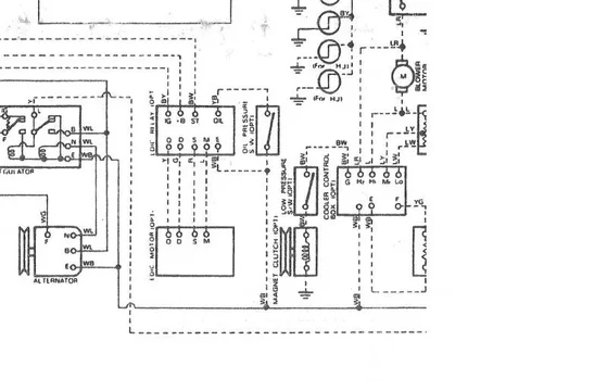
By the way Theo..... this BJ40/BJ43/HJ47 wiring diagram suggest the "unknown brown" is actually a 12 +Ve feed off the battery (via a fusible link). ............ Labelled as "+B" if I'm reading it correctly. (Dunno its purpose!)

And it also confirms that Toyota used "black with a yellow stripe" as the loom colour-code for "IG" ..... in contradiction to the "red with blue stripe" colourcode used on the FCR pigtail for "IG".

All the other colour-codes agree (according to this FSM diagram)

BJ40BJ43HJ47Wiring.webp

:beer:

PS. I've noticed the "0.I terminal" may be labelled simply as "0" (both stand for "overinject") depending on what diagram you're looking at.
BJ40BJ43HJ47Wiring.webp
 
Last edited:
Righty-ho.

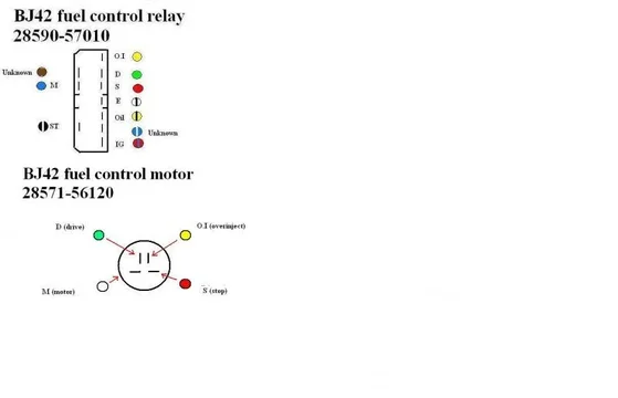
Continuing in my quest to really get to know our fuel-control/EDIC systems - I've been studying the FCM for a BJ42.

In this image, I've included the terminal layout of the FCM pigtail plug (with its male spades) underneath the one for the FCR:

12VBJ42FCRFCM.webp

The only colourcode that differs from the the loom and the FCR pigtail is the "white" M wire. (In the loom and FCR this is "blue".

Now if I clip an earth lead onto the FSM and apply 12V +Ve to the "M" terminal, the arm oscillates/swings backwards and forwards continually between the "overinject" and "stop" positions (passing through the "drive" position with each swing of course).

BJ42FCM.webp

Removing the juice allows the arm to stop absolutely anywhere within its swing.

So my conclusion is that the "S" "D" and "O.I" wires do provide feedback to the FCR for it to cut the power to "M" when the arm reaches their designated positions..............Am I wrong?

(I'm resisting opening up the FCM for the time being.)

:cheers:

PS. :hhmm:And Theo - Why do you assume you can fit your FCM with its arm in any random position and that it will automatically put itself in the correct position (stop position) when you connect that connector? Perhaps it should do that ...... but I don't know enough about the operation of the FCR to decide. (I need help :frown:)
BJ42FCM.webp
12VBJ42FCRFCM.webp
 
Last edited:
If you look at the schematic Tom, you will see that there are no connections from the FCM to the FCR circuit. If it wasn't for the oil pressure/delay functions, L2 could be run directly off IG, as L1 runs off ST. As I have looked at the FCR circuit in some detail, it is clear to me that this is it's only function so therefore the rest is being done by the FCM. I have not looked inside my FCM (yet) but I have seen similar control motors in the past so I have a rough idea of how the FCM would work. You need to eliminate either the FCR or FCM as a mystery so you can get some sleep and stop counting FCR's and FCM's lol.
 
If you look at the schematic Tom, you will see that there are no connections from the FCM to the FCR circuit. If it wasn't for the oil pressure/delay functions, L2 could be run directly off IG, as L1 runs off ST. As I have looked at the FCR circuit in some detail, it is clear to me that this is it's only function so therefore the rest is being done by the FCM.....

I will duly study that schematic again tomorrow Alex.

...I have not looked inside my FCM (yet) but I have seen similar control motors in the past so I have a rough idea of how the FCM would work. You need to eliminate either the FCR or FCM as a mystery so you can get some sleep and stop counting FCR's and FCM's lol....

Now you've put your foot in it! ;)

Since you've stated you may have a rough idea of how the motor knows where to stop ...... I may have to ask YOU to enlighten me if I still fail to understand (using words of no more than two-sylables of course).


:cheers:

PS. But I will consider delving inside that FCM and posting pictures of its hidden secrets if you consider such drastic action is necessary to confirm or refute a theory! :D
 
Last edited:
PS. :hhmm:And Theo - Why do you assume you can fit your FCM with its arm in any random position and that it will automatically put itself in the correct position (stop position) when you connect that connector? Perhaps it should do that ...... but I don't know enough about the operation of the FCR to decide. (I need help :frown:)

My logic is dangerous TOM but the FCR only allows the arm to stop in one of the 3 fixed different positions so if the FCR and FCM are working as they should then why not ?
 
On the ones I looked at they worked by routing the motors power through the internal switches. Looking at the motor schematic you will see that Earth is connected to the outer contact of the rotor, while Positive +BP is connected to the inner. 0.1, D and S are switch contacts. E and +BP are just the feeds. Could have been drawn a bit less confusing by Toyota I guess.
 
Last edited:
My logic is dangerous TOM but the FCR only allows the arm to stop in one of the 3 fixed different positions so if the FCR and FCM are working as they should then why not ?

Why not indeed Theo! (You get one of these :flamingo:...Not that I really know what a pink flamingo standing on one leg is supposed to mean in smilie language!)

On the ones I looked at they worked by routing the motors power through the internal switches. Looking at the motor schematic you will see that Earth is connected to the outer contact of the rotor, while Positive +BP is connected to the inner. 0.1, D and S are switch contacts. E and +BP are just the feeds. Could have been drawn a bit less confusing by Toyota I guess.

Clear as MUD Alex. :bounce2: (You get a "bounce 2" - and I don't know what that is either.)

By the way - I'm pretty sure you should be writing your O.1 as O.I (capital i) because it must surely stand for "overinject" (just like "D" must stand for "drive" and "S" must stand for "stop").

And in payment for assisting you to correct this serious error ..., answer me this (pleeeeeeese). Is there someway I can get the FCM to stop in one of these O.I, S, or D positions using test leads? I tried very briefly touching "12V +Ve" on these FCM terminals and this resulted in a spark - much like "a direct short-to-earth". While earthing them resulted in nothing at all. Meanwhile the arm just carried on merrily waving to me!

And if I can't - Why not?

:beer:
 
Last edited:
Yes you could get the motor to stop but you would have to replicate the given relay positions with test leads. To tell you the truth when looking at that diagram my head spins first for a while before the rotor starts spinning with various relay positions in my mind :lol:
Notice P3 of Relay 1 (bottom) connects to moving contact arm of Relay 2 which makes it all the more confusing. Relays 1 & 2 plus the motor contacts form a logic circuit. The best way to replicate it Tom would be to use 2 DPST toggles switches wired up like the relays, otherwise it might be a bit mind boggling with all these test leads hanging off the thing.

Funny you picked up on that 0 and O mistake (and yes you are right). I don't know how many times in programming I have made that error (because 0 "sounds the same as" O) and spend lots of time trying to find the bug. Thus I use Terminal Font for serious stuff, that puts a slash through the 0.

edit: oh you're talking about the 1 versus I lol.
It's that damn diagram that's doing it to me. Think I'll go outside for a cig and get some space :eek:
 
Last edited:
Just verified that the relay positions in the diagram are in Ignition switch OFF position. So UP on the relays on the diagram corresponds to UP on the relay contacts on the FCR too.
That should help somewhat.
 
.. and "S" must stand for "start").


:beer:

Just when I thought I was starting to see some light at the end of a very long tunnel and that "S" stood for "Stop" ;)
 
Yes you could get the motor to stop but you would have to replicate the given relay positions with test leads. To tell you the truth when looking at that diagram my head spins first for a while before the rotor starts spinning with various relay positions in my mind :lol:
Notice P3 of Relay 1 (bottom) connects to moving contact arm of Relay 2 which makes it all the more confusing. Relays 1 & 2 plus the motor contacts form a logic circuit. The best way to replicate it Tom would be to use 2 DPST toggles switches wired up like the relays, otherwise it might be a bit mind boggling with all these test leads hanging off the thing....

Just verified that the relay positions in the diagram are in Ignition switch OFF position. So UP on the relays on the diagram corresponds to UP on the relay contacts on the FCR too.
That should help somewhat.

I'll study what you say here in more detail soon Alex. Meanwhile I've rushed outside and done some tests that came to mind as soon as I woke this morning. (I think my subconscious must have been working on this while I was asleep :lol:) Oh - I did have breakfast before rushing out! (I'm not THAT dedicated.)

The results make me think AGAIN that the FCM REALLY IS giving feedback to the FCR (on where the arm lies)


I've found that normally terminals S, O.I and D are all earthed. But this earth circuit is broken each time the FCM arm crosses their position. (Except that this happens for "D" only when the arm is travelling anticlockwise.)

So based on these finding, here is how I would advise people to checkout their FCM (if they ever consider it may be faulty):

FeedbackTheory.webp

Just when I thought I was starting to see some light at the end of a very long tunnel and that "S" stood for "Stop" ;)

Okay Okay Okay.....................Error corrected :p
FeedbackTheory.webp
 
Last edited:
Now then............:hhmm:

Theo started this thread. And it was to do with his BJ42! But really Alex and myself aren't the least bit interested in his BJ42! Because we each have the older BJ40. (And we all know older is better - after all - why else is everyone here working on old stuff.)

Herein could lie the answer in how Alex and I could both be right. .......... Perhaps

Maybe "feedback" occurs only in the BJ42 set-up?

Take a look at the connections on my BJ40 FCM (28571-56030):

BJ40FCMconnectors.webp

Yep. There's TWO connectors (not just the meeeserly one for a silly BJ42). And the wires on the loom side of the triple-spade connector (the two LW colourcoded wires) are really beefy b#astards! Now that's an extra 3 wires to/from the FCM compared to the BJ42.

What say you Alex? (Shall we hijack his thread to concentrate solely on our BJ40 FCRs and FCMs now that Theo is "out of action" waiting for his new BJ42 FCR to arrive on the slow boat from Japan?) :lol:
BJ40FCMconnectors.webp
 
Last edited:
...Herein could lie the answer in how Alex and I could both be right. .......... Perhaps

What say you Alex? (Shall we hijack his thread to concentrate solely on our BJ40 FCRs and FCMs now that Theo is "out of action" waiting for his new BJ42 FCR to arrive on the slow boat from Japan?) :lol:

The BJ42 setup is obviously a bit different, and one of my favourite sayings is "don't just assume, look". So yes Tom, we could both be right.

I don't mind if Theo is ok with this.

Watrob you need to get yourself a real 40 series... :lol:
 
I think both you chaps need to mothball those two old BJ40's and get into the real world. The minimum for this theard is a BJ42, HJ47(2H) or HJ60(2H):doh:

The BJ42 setup is obviously a bit different, and one of my favourite sayings is "don't just assume, look". So yes Tom, we could both be right.

I don't mind if Theo is ok with this.

Watrob you need to get yourself a real 40 series... :lol:

Hear hear!! :clap: well said Alex. And a true "Forty (40) Series" surely needs to have a "four" and a "zero" in its model designation.

Actually .... we may have to mothball progress on "the BJ40 front" anyway because I don't have a spare BJ40 FCR or FCM lying around to play with.

I have my "feelers out" for them - but they may take me months or even years to aquire. (No rush - Plenty of other things to do meanwhile!)

BJ42 gear is easier to come by here. And I bought those BJ42 items recently to hold as personal spares so it has been worthwhile to find out just how different/incompatible they are. (Although some internal parts must still be interchangeable so I'm not disappointed I got them.)

And I'm not prepared to take my existing FCR and FCM off my cruiser right now simply for the sake of experimentation/research.


:cheers:
 
Lostmarbles - Do you guys have HJ 45 'cruisers over in NZ? If you do, a FCR can be liberated for your purposes from one of these vehicles.
 

Users who are viewing this thread

Back
Top Bottom