I figure I may as well add to this thread - might as well keep all the 8274 info in one place.
A few years back I converted my 24V diesel patrol to 12V and converted my 24V 8274 to 12V. Here's the write up from my website. This may help someone that wants to do the same conversion or vice versa or just to understand the wiring difference of the 24V model.
----------------------
Next the winch retrofit from 24V to 12V. I purchased a new 4.5HP 12V Warn style motor in the US and brought it back with me.
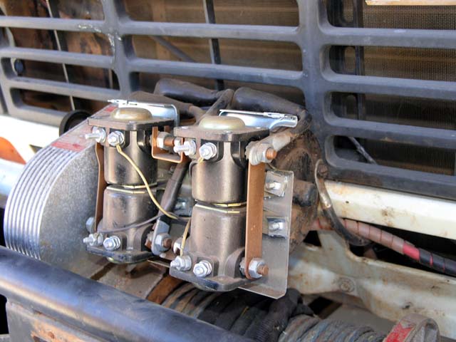
Here's the winch before I started the motor swap. NOTE: the solenoids on a 24V winch ARE 12V solenoids, each pair (cross connected) are wired in series - BUT read below! For 12V operation the control signals are rewired for parallel operation. Of course I bought 5 (4 + 1 spare) 12V solenoids thinking that Warn used 24V solenoids in their 24V winches. Guess I have 5 spare solenoids now
")
.
There is a subtle difference in the solenoids between a true 12V winch and a 24V winch. On a 12V winch ALL 4 solenoids have a common ground path through their body, hence only a SINGLE control wire goes to each solenoid and hence each cross connected pair is in parallel (12V operation). In a 24V winch the UPPER 2 solenoids have a common ground path through the body BUT the bottom 2 solenoids are DIFFERENT in that they do NOT have a ground path through the body. This means that the bottom 2 solenoids have 2 control wires and each one is wired IN SERIES with the cross connected mate - hence 24V operation. Took a bit of head scratching to figure out this subtle difference...
You can see how NEW the old solenoids look, the winch has been on my MQ for over 20 years - having a good fitting water proof cover is the reason. It may look all macho to have the winch exposed - but I'll keep the cover on mine...
Here's some new hookup info to rewire the 24V solenoid for 12V operation (remember that the solenoids ARE 12V, regardless of 24V or 12V operation - they are just wired in series for 24V and parallel for 12V).
The following picture shows how the control box is wired for for 24V operation (as a reference). The key is to note where the Black and Green wires connect from the Control Box. Basically the Black and Green carry 24V from the hand control to energize one cross connected solenoid pair or the other cross connected solenoid pair.
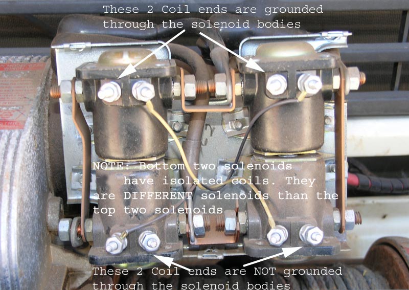
The next picture shows the original wiring (that will be left EXACTLY in place). The ONLY thing that needs to be 'rewired' is the Black and Green wires from the Control Box and the addition of 2 new wires to provide Ground connection to the bottom 2 solenoids. As noted in the picture the top 2 solenoids are DIFFERENT than the bottom 2 solenoids (i.e. they have DIFFERENT part numbers).
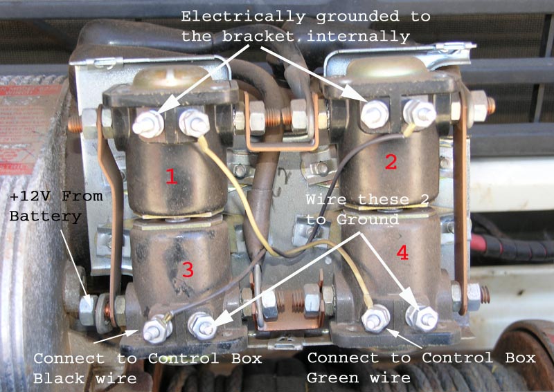
The next picture shows where the Black and Green Control Box wires need to be rewired to. It also shows where new Ground wires need to be connected to the bottom 2 solenoids. You can wire the new bottom 2 solenoid wires to the top two solenoid coils (where there are no wires originally - since those two 'lugs' are electrically grounded through the body of those 2 solenoids).
Once you have added in the new ground wires for the bottom two solenoids AND moved the Black and Green Control box wires to the new positions what you have done is wired the solenoids in Parallel (for 12V operation) rather than in Series (for 24V operation). So, for 12V operation Solenoid #2 and #3 coils are in parallel and Solenoid #1 and #4 coils are in parallel. (Originally, for 24V operation, Solenoid #2 and #3 coils are in series and Solenoid #1 and #4 coils are in series).
That's all there is to it. Of course you ALSO need to change the motor to a 12V unit as below...
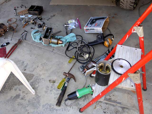
The new 12V winch motor installed into the top of the gear box. Anyone need a good running 24V Winch motor? Once the back plate is removed off the motor the brushes will be exposed and they will slide off the commutator. that allows the motor to be pulled clear of the housing and installed onto the gear box.
Close up of the motor installed in the box. I chose the original style keyway motor from the supplier I bought the motor from. I had to clean off the old sealant and then applied some new non-hardening gasket forming material. Pretty simple looking in there eh? The knob on the left just slides the gear on the motor shaft clear of the large gear - that disengages the motor and allows the cable to be easily pulled off the drum.
cheers,
george.