@NobleVentures What level of availability, kms and price have you experienced looking for a L83? And any thoughts on complexity/reliability when comparing to a LM7?Super thankful for this consolidated thread. Incredible work! I'm about to purchase an L83 with 6180e 4x4 tranny. Any insight on why I should NOT use that drivetrain? Read a lot on disabling the AFM... but want to confirm that 4x4 transmission is suitable if the adapter is used for transfer case?
Navigation
Install the app
How to install the app on iOS
Follow along with the video below to see how to install our site as a web app on your home screen.
Note: This feature may not be available in some browsers.
More options
Style variation
You are using an out of date browser. It may not display this or other websites correctly.
You should upgrade or use an alternative browser.
You should upgrade or use an alternative browser.
How to LS Swap a FJ60 or FJ62. Quick and dirty guide for regular folks wanting to do an engine swap in their driveway. (5 Viewers)
- Thread starter dbbowen
- Start date
This site may earn a commission from merchant affiliate
links, including eBay, Amazon, Skimlinks, and others.
More options
Who Replied?TexasLandCruiser
SILVER Star
Is this marketing? Not a loaded questionwe were talking about fuel rails. Nice dig.
I still don’t agree with vapor lock on a EFI pump but whatever if you want to listen to some marketing dude with clean hands
Cavitation is a natural process that occurs when vapor bubbles are introduced into liquid under pressure. All electric fuel pumps are susceptible to this force. Its most common cause is installer error, where an inadequate fuel supply increases the suction on the inlet side.
Cavitation is literally boiling the fuel through pressure. Vapor bubbles form and then split, causing a micro-explosion. This is extremely damaging, as even a few minutes of cavitation can ruin a fuel pump.
Another cause of failure is over-heated fuel. Not running a return line (dead-head style) or attempting to plumb the return line into the feed line (not into the tank) causes hot fuel to cycle back through the pump, heating it up more. The hotter the fuel, the easier it is to cavitate or even vapor lock. Yes, EFI systems can vapor lock too. This is why a proper return system is so important for EFI.

LS SWAPS: Fuel Systems Guide
LS SWAPS: Fuel Systems Guide Includes in-depth instruction and photos. Covers all the criteria to consider when starting an LS swap project
- Joined
- Jul 22, 2012
- Threads
- 585
- Messages
- 16,588
- Location
- Winter Park, Florida
- Website
- www.cruisermatts.com
You realize the majority of LS cars and trucks are returnless right? They all are after 2008.
Yes in-tank pumps are a good idea.
No, overheated fuel is not going to vapor lock a 50-60psi gerotor pump.
Please explain how fuel is going to get hotter then ambient anyways sitting in a tank.
The fuel coming back from the return on my LS race car has never want above 80F btw. There is a temperature sensor built into the Flex sensor.
Vapor lock is a issue with low pressure carb pumps drawing from 10ft away from the fuel source. "vapor lock " is a easy term to latch on to from a marketing perspective because old people had to deal with that for decades with crappy old fuel systems that were an every vehicle
^my opinion. as someone who sells and installs retrofit EFI systems very regularly
- Thread starter
- #144
You are referring to the trans cooler here I assume? Then yes, agree. Would your engine donor vehicle (Silverado) have had a PS cooler in stock setup?
The Silverado had a cooler in the radiator but if you got the towing package you got an external cooler that went infront of the ac condenser. I used a radiator that did not have a cooler and went straight to a super high gvw external cooler and it have been great.
You are referring to the trans cooler here I assume? Then yes, agree. Would your engine donor vehicle (Silverado) have had a PS cooler in stock setup?
@Cruisunder im so sorry i got mixed up and read about the trans coolers haha. I think the external PS cooler is added because the stock configuration is for it to go into the rad. If you are routing your trans lines into the rad and then into an external cooler for the trans, youd want to add the extra ps cooler. Got my wires crossed. @Megadoomer has the right answer here
TexasLandCruiser
SILVER Star
The regulator has been a nice addition and working well. Not everything is black and white. As you know. The off-road race shop that just finished the work made a good addition with the pump, regulator, lines, and engine work. I have to disagree with your implication it was unnecessary.You realize the majority of LS cars and trucks are returnless right? They all are after 2008.
Yes in-tank pumps are a good idea.
No, overheated fuel is not going to vapor lock a 50-60psi gerotor pump.
Please explain how fuel is going to get hotter then ambient anyways sitting in a tank.
The fuel coming back from the return on my LS race car has never want above 80F btw. There is a temperature sensor built into the Flex sensor.
Vapor lock is a issue with low pressure carb pumps drawing from 10ft away from the fuel source. "vapor lock " is a easy term to latch on to from a marketing perspective because old people had to deal with that for decades with crappy old fuel systems that were an every vehicle
^my opinion. as someone who sells and installs retrofit EFI systems very regularly
- Joined
- Jul 22, 2012
- Threads
- 585
- Messages
- 16,588
- Location
- Winter Park, Florida
- Website
- www.cruisermatts.com
The regulator has been a nice addition and working well. Not everything is black and white. As you know. The off-road race shop that just finished the work made a good addition with the pump, regulator, lines, and engine work. I have to disagree with your implication it was unnecessary.
YODA 88 62
SILVER Star
For exhaust you have a couple of considerations and pros and cons for each of them. Really there are two choices here. Take it to an exhaust shop, or do it yourself.
If you decide to take it to a muffler shop, you dont have to worry about messing with it as the shop will be doing it. There are two types of exhaust shops. The ones who build custom exhaust using stainless mandrel bends or pie cuts, use tig welders, and cost a lot of money... and the kind that use mild steel, tube benders, and mig welders. You will definitely pay for the difference here, as a shop at the former will cost over $2-3K or higher and the latter will be $1.5-2K in expense. You are paying someone else to do all the work for you and the exhaust needs some clever routing.
The downside to using the cheaper option is that the mild steel will rust. Every single bend in your tube will have a crush in the inside corner of the bends. The benefit is that its cheap, quick, and you dont have to do anything.
A good middle ground here is just doing it yourself. There are a bunch of ways you can do this to be cost effective, but it will cost you your time. I was able to do my own exhaust using high quality name brand stainless parts, stainless tubing, quality exhaust connectors for less than half of what i was quoted at a local exhaust shop to build the same exhaust out of mild steel using unknown parts. Think long and hard on this because the exhaust will be important. You have done all of this work so far on your LS Swap, might as well give the exhaust a shot. Before doing this, i have never welded any type of exhaust before.
The rest of this post is assuming you are planning on doing this yourself. A few things to keep in mind before even getting started.
-welding exhaust is all about fitment. You can not cut exhaust tubing with an angle grinder and cut off disc and expect it to look good or weld properly. Gaps in the fitment will cause really bad welds and your mig wire will blow straight through the work piece.
-You will need access to the proper cutting equipment
-you can use a mig welder on stainless exhaust just fine
-a belt sander is a life saver
-a rolling creeper will save your lower back!
So for fitment, it is really important you have access to a way to cut true square straight cuts in exhaust tubing. Heres a few from cheapest to most expensive:
-On the cheaper end of this you have an abrasive chop saw. This is basically a giant angle grinder that you use like a miter saw. These are cheap, loud, and make a ton of grinding dust and each cut will be needed to be cleaned up quite a bit.
-Portable band saw with a blade that will cut stainless can be used if you clamp your material down in a vise, but you have to keep a steady hand and ensure your cuts are very straight. Swag offroad makes stands for these that will turn them into vertical band saws.
-Cold chop saw like the evolution metal cutting chop saw will make quick work of this and give you super clean cuts with minimal clean up, but is very loud
-horizontal/vertical band saw with blade to cut stainless is the best bet here. This is the most expensive option though and not everyone will have access to this.
The way you are cutting these tubes is really important. If you want to butt two pieces of tubes together and weld them, you need perfect fitment. your cut across the pipe has to be perfectly square so the circle of the tubing is completely intact. An angle in your cut off of square will turn your round tubing into an oval and create gaps, weird connections of pipe that dont line up, and airflow restrictions. A nice way to get around not having perfect fitment is to use a tube expander to create a slip fit connection between the two pieces of tubing. These are nice because it will create a good fitment, and you do not lose any tubing diameter in the process. I personally did not like the look of the slip fits so i just made sure to ensure proper fitment and butt welded everything. If you use slip fits, your mandrel bend kit will come with slip fit ends already in them.
Something that will save you hours on this project is a belt sander. It will clean up your cuts and you can put a tiny bevel around the edge with ease. Then just wipe with acetone. You got to be careful cleaning up your cuts with a flap disc because you can easily create gaps in fitment by removing too much material.
Another thing to keep in mind is that whether you are Mig welding or tig welding, using mild steel or stainless… the material prep is just as important or if not more important than the welding technique. You can be the best welder on the planet but if you are welding contaminated improperly fitting materials it will never turn out looking good. For butt joint welds you have to have no gaps. I can’t stress this enough. Everything has to butt up together perfect.
Materials must be cleaned properly. After you cut each section of tube you will want to wipe each weld surface down with acetone and make sure it’s deburred. If you are using stainless exhaust you will want to use a sanding belt or abrasive disc or flap disc that has only ever seen stainless steel. For example if you use a sanding belt that has sanded mild steel you could potentially impregnate your stainless tubing with fine bits of mild steel and your welds will rust before your tubing. If you want to go even more OCD, just before welding you can hit the weld surfaces with a torch to burn off any remaining oils.
Now that you have a way to cut the tubing all lined up, you need to decide on what parts you are wanting to use. Whether or not you are wanting to use catalytic converters, and what kind of exhaust tubing you are wanting to use.
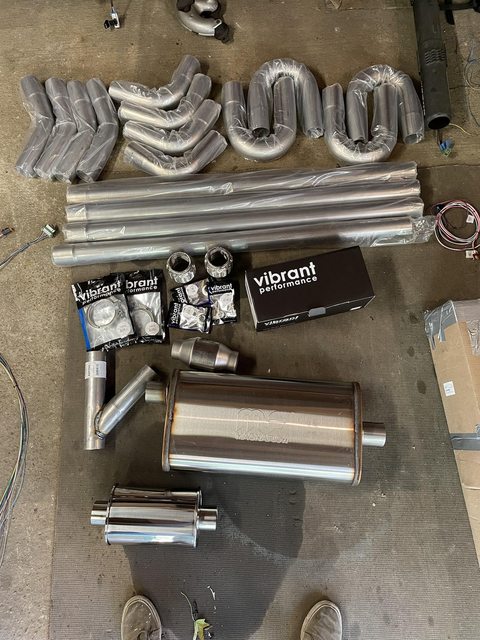
For tubing you can use mild steel, aluminized steel, 409 stainless, or 304 stainless. In that order it goes cheapest to most expensive, and will rust more to will rust the least. You can order the tubing from summit in a kit that comes with way way too much pipe that will have a lot of straights, and different angle bends. These posts are assuming you chose 409 or 304 stainless. Honestly, 409 is just fine for an offroad truck exhaust. Most of the "stainless" mufflers you buy are 409 stainless and not 304... looking at you magnaflow. If you look at the photo below, you can see that the muffler looks different than the resonator. Thats because Vibrant uses all 304 stainless and magnaflow uses 409
As far as diameter goes, 2.5 or 3 inch is just up to you. It is much easier to tuck up 2.5 inch tubing so that is what i went with. You could go 2.5 tubing to 3 inch once the two pipes hit your connector pipe as well. I wish i did this, but i just did 2.5 all the way back because i didnt feel like buying more exhaust tubing
Cats or not, thats a choice for you to make, as well as mufflers. There are entire threads on both of those topics longer than this swap thread. For me personally I stick to straight through mufflers, and stay away from chambered mufflers like flowmasters as they are more restrictive and i dont personally care for the sound of them. Cats will keep your exhaust from smelling like gas, thats about it. The longer the muffler, the quieter it will be. I used a 22 inch magnaflow straight through muffler with a vibrant ultra quiet resonator and it sounds absolutely amazing. Nice and quiet at idle. Opens up when you get on it, absolutely zero drone or rasp.
You will however want a resonator, as it will eliminate highway drone and exhaust rasp and pop.
There are many many ways to connect exhaust pieces, and for this exhaust you will at least need 4 connectors. I have yet to find anything that beats Vband clamps. In comparison everything else just seems old and outdated. No gaskets, easily removed and can be installed very quickly. If you splurge for anything in this, buy nice Vibrant vband clamps. You can do some research but they are machined differently than cheaper vbands to ensure proper fitment and no leaks. I would rather have a cheaper muffler than not have these vbands.
Youll need 2 flex joints, I used vibrant for these too but you can save a little money on these as well. These will allow your exhaust to move with your motor and alleviate the stress on your exhaust tubing.
You will also need one weld on exhaust hanger and three stainless exhaust hanger rods. Just get a straight rod for this, youll heat and bend it to suit your needs.
Last youll need a Y pipe or an X pipe (explained later) and 3 vibrant weld in O2 bungs with one O2 cap.
Heres an image of just about all the exhaust parts, missing 2 v bands here and the Y pipe in this photo looked way better online. Dont buy one like this, its garbage. Notice that the muffler is center inlet and offset outlet. Youll need this offset outlet to clear your driver rear shock absorber.
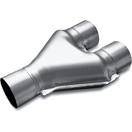
This is the type of Y pipe you would want.
If you were using an X pipe you would want this.
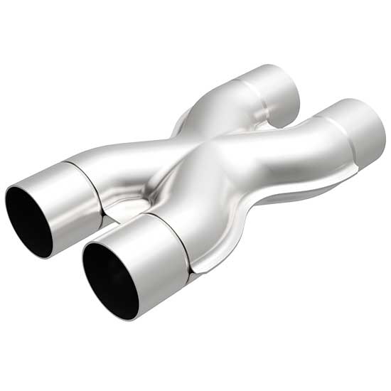
The Xpipe will sound much better and has better exhaust scavenging than the y pipe will, but the y pipe will be much easier to install.
Now that you have your parts you are going to want to figure out the routing of the exhaust. Theres really two ways you can do it, either run a crossover under your front output of your tcase or over the rear output of your t case. From there you will be able to figure out what muffler and joiner pipe to use.
I chose to run the crossover under the front output of my transfer case as it gave me more room for a resonator and muffler on the drivers side of the transmission. It also gets the hot exhaust pipe away from your wires and fuel lines quicker this way. This is what i would recommend.
From here youll decide on the piping. you have a lot of options. Join the 2 sides of the exhaust into a y pipe then go back as one exhaust using a 1 in 1 out muffler and follow the stock exit location. You could also join the 2 sides of the exhaust into an xpipe and into a 2 in 1 out exhaust and back out to the stock location or even run both sides of the front exhaust into an x pipe and 2 separate mufflers and do true dual exhaust out the back. Only use the Xpipe if you are not planning on running a resonator. You can use two small bottle style resonators towards the end of the exhaust but they wont be as effective as a larger one more upstream.
As far as the resonator goes, you want this resonator to be as forward in your exhaust, closest to the motor as you can get it. The further back it is, the less it will do its job and the worse it will sound. A lot of the newer mustang 5.0s have this issue because they run the resonators all the way at the end of the exhaust right at the exit tips.
You will also need an anglefinder, i used a cheap digital husky one from home depot with great success, as well as a pack of zip ties, some sharpies, and a steel ruler.
As far as welding goes, you can weld stainless with mig, as long as your mig welder has a stainless setting. I welded all of this on a miller 211 on stainless setting, but you will have to use the appropriate wire. Hobart makes wire specifically for stainless, its ER308L. 0.030in wire works just fine. Technically you should use Trimix welding gas (mostly helium with argon and co2) to mig weld stainless, but i just used normal C25 (25% CO2/75% Argon) and it welded fine. It just spatters a bunch and isnt as shiny and pretty. I am planning on tearing all of this out and tig welding a new exhaust down the road, but ive not had one issue with any of my mig welds on my current setup.
There are HOURS of DIY exhaust videos on youtube. Make sure to watch the videos of the guys tig welding stainless exhaust, while you might not be doing that level of work, its good to see how they work and what they do before you give it a shot. You can get a good idea on cutting, fitment, routing, etc. Theres a lot out there to watch. Other good videos to watch are videos of guys building custom turbo charge piping as its similar in routing and cutting and fitment.
So at this point you should have a way to cut your exhaust tube, a way to clean your cuts, your exhaust system components, and a relative idea on the routing of your exhaust. All thats left is to just go do it.
Thanks for building this thread. There’s tons of great information to ease the process.
As I start an LS build, I remembered your exhaust posts. The first muffler shop exhaust only lasted a couple years before rusting out.
The second exhuast, pictured, is a 15ish year old exhaust done by a backwoods muffler shop. Not the best welds, but they never leaked. Cracked on one mount…prob due to sliding the exhaust on rocks. The restriction is pretty significant, especially at the exit. After completely building one homemade exhaust from the headers back, it is well worth the time to build your own exhaust.
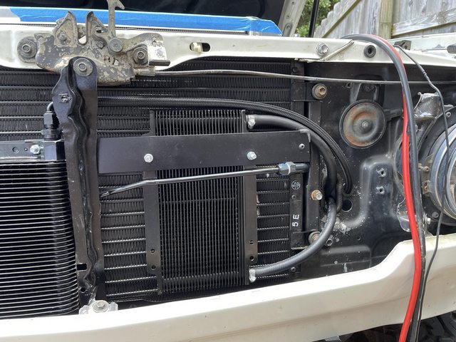
Next youll want to run to the steel yard or home depot or wherever and get a rectangle flat stock of steel. This is kind of how I mounted my coolers to my AC Condenser. Make sure you space out the metal strip out so your Trans cooler is NOT touching your condenser. You dont want any of this stuff touching each other. You will probably install and remove this thing 20 times to get it just right. There are other ways to mount these two coolers, this was just the easiest (definitely not the prettiest) way I did it.
You will also need to take a step bit to the core support right next to the oval holes for your Trans lines to run through. I ended up not using one side of them, but i did both sides to make it symmetrical. Use firewall gromets on these holes to make sure you dont cut your lines that you are planning on running through it. That center support on the hood latch was still touching my trans cooler in this pic and needed to be trimmed more.
The Power steering lines are really easy and come in a kit with the B&M Power steering cooler PN:70255.
Next up is your trans cooler lines. Remember how earlier you decided if you were going to reuse your hard lines or put those -6 adapters in the side of your transmission to use AN hose? The following will be assuming you chose to use the AN hose for your cooler lines.
In total for my swap i used 25 feet of AN hose. This is for the fuel line and the trans lines. The hose is not something you want to cheap out on. I used Vibrant -6AN nylon braided hose that is rated for ATF, gas, and e85. The hose i used was VIBRANT PN:VPE-11976 for 20 foot length and VIBRANT VPE-11986 for 5 foot. For the trans cooler system youll need quite a few fittings. You will need six 90* -6AN fittings. You can use summit brand if you want to save some money, or vibrant 21906 for nicer ones. If you want some seriously awesome ones you can use deatschwerks 6-02-0803 Titanium anodized. Dont buy cheap chineese fittings though. For trans lines the summit or jegs ones are fine. Just to be safe maybe grab 30 feet of hose so you dont run out.
You will want to run an external cooler for the 4l60e and B&M PN: BMM-70266 works really well. For this you will need two -6 to NPT adapters to connect your lines. Use plumbers tape on the NPT side but NOT the AN side. The adapters are PN: SUM-220649B for the black ones.
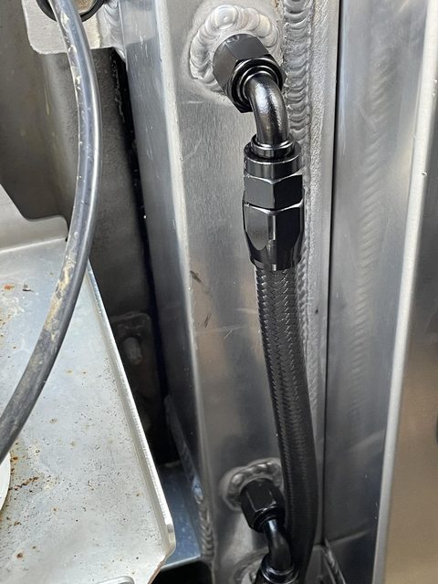
Ok now that you have all of the parts You will need to build out your lines. This was really fun and one of my favorite parts of the swap because it looks professional when youre done and if you do it right looks super clean when you install them.
The bottom outlet on the trans is the hot side. It will flow to your upper radiator fitting for the trans cooler. Run your line down your bellhousing, along the oil pan and then do a 90* left turn along the bottom of where the radiator is and then all the way up to the top outlet on your ratiator. Make sure to give yourself a little bit of slack here. You are doing this to size the line out from the longer 20 foot section of line. What you are trying to accomplish here by the radiator is tucking the hose up and under the radiator to hide it. Once you have the length you need cut this hose and take it to your bench.
You will need a bench vise and some soft jaws for this. Vibrant makes some that are anodized black VPE-20990. Install a 90* -6AN fitting to both ends of this hose. If you are worried about scratching the anodizing on your fittings, wrap the soft jaws in painters tape.
This is a video on how to install the fittings onto the ends of the hose. Dont bottom out the two metal pieces of the fitting, you want a tiny tiny gap, and do not use any sealer or anything on any of the threads. Make sure to lube threads of the part that is going to go into the hose with engine oil or something similar. You dont need a special AN tool for this s***. Use an adjustable wrench or some Knipex pliers if you have them. To cut the hose, wrap the hose where youll cut in painters tape and cut it with a cut off disc and an angle grinder.
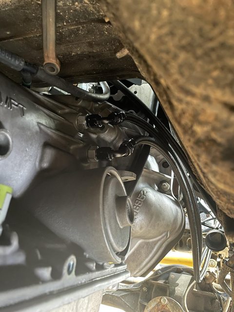
OK now that you have the hose done youll connect the 90* fitting to the bottom outlet on the trans and run it up to the diagonal frame brace, tuck it up over that brace and feed it under your core support and up the side of your radiator and connect the other 90* fitting to the top AN port of your radiator. hand tighten these for now.
Under the radiator, where you installed the nutserts earlier, secure the hose to the fan shroud using Adel Clamps and a bolt. Dont tighten them too tight for now to allow for some movement.


Next youll run your hose from the lower radiator AN port, out your firewall and above the power sterering cooler to the right side port of the Transmission cooler. Mark your hose and cut it. Remove the hose and take to the bench and install a 90* -6 fitting on each end. Once those are installed snake it through your hole in the firewall and attach one end to the radiator port and the other end to your trans cooler using the NPT to -6 AN adapters. Use teflon tape on the NPT side but not the AN side. You can tighten both ends of this hose all the way since you wont need to adjust it much when you tidy it up.
The last hose for your trans lines will be from the left side of the trans cooler, out through the firewall, down the frame to the point where it reaches your first long line. Run the line parallel (important) to your other line that you previously made earlier. Run it to the upper port on the Transmission where your AN adapter is and mark the hose to be cut. Take it to the bench, install 2 90* AN fittings and then mount it in the truck. Leave these hand tight.
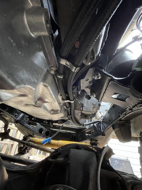
The front of your truck should now look like this:

And you should have your two long hoses just kinda dangling down in there like this with the AN fittings finger tight:
Next youll use more Adel Clamps and a few AN hose holders to organize this stuff up and make it look like you know what you are doing. On Amazon you can order some 6AN Hose Separator clamps made from aluminum.
6AN Hose Separator Clamps
Here are some Adel clamps while you are there.
Adel Clamps
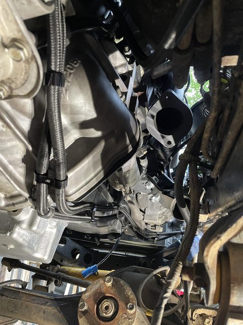
Youll first attach these Aluminum clamps to your AN hoses loosely to see where you need them then you can twist them and route them up along your trans pan and oil pan to tuck them up super tight and nice and away from your exhaust. These clamps are great. Use the Adel clamps in the oil pan bolts to secure the lines.
After you are done with the routing, go back and tighten all of your AN fittings. DO NOT OVER TORQUE THESE. Your Transmission lines are all done at this point and half of your power steering lines are done.
Now that you have these all routed super nice and pretty and professionally... you can now wrap them in DEI heat wrap so they dont get hot from the exhaust. This isnt really necessary but I went full overkill on this wrap stuff. Your hoses will go from looking super tidy to looking like a food truck burrito. Once you do your fuel lines and stuff you can wrap those too. more on that later I just wrapped the velcro style heat wrap 3/4 around the hoses and secured them with stainless steel zip ties.

For your power steering hard line, you have some options. IMO the best option is to find a local hydraulic hose shop and have them make one for you. The GM pump high pressure port and the high pressure port on the Toyota box have the same attachment size on both ends. Its M16x1.5 with a flare in the hose. You can measure out the line and have a shop make them for you. A guy in Memphis named Metal Mike at Automotive AC Hose repair makes them for literally everyone here in Memphis not just land cruisers. I bought a prebuilt hose for this swap from a 3rd party supplier (not mike) that used an AN fitting as an adapter. The hose itself was made by Mike here in town. The adapter that is sold with the hose is the incorrect size (-5 or something, it was too small) and made of aluminum. If you go this route, youll want to toss the adapter in the trash immediately, buy a Stainless Steel M16x1.5 to -6 adapter and use that. I didnt and had my entire steering box leak out and blow back onto all of my freshly swapped stuff. The Steering box is like cast steel or something and the hose is also steel, so stainless is the way to go for this adapter fitting piece probably not aluminum.
After you get that hose done, your power steering is done as well.

Is it possible to use an OEM style radiator with a 5.3 / 4L60E swap? My radiator was brand new 2 years ago for my 3FE. I have a CFS 2708 radiator from Summit Racing currently in the truck.
- Thread starter
- #149
yeah you sure can. you will just have to get a little creative with the radiator hoses since the fill and return on the V8 are both on the passenger side of the motor. Youll also need to add an in line steam port. You can still run your Trans fluid into the cooler, and then out to an external cooler before running back into the trans. Im not sure if your shroud will line up if you properly offset the V8 to the driver side, but there are a few DIY shrouds on speedway that you can useIs it possible to use an OEM style radiator with a 5.3 / 4L60E swap? My radiator was brand new 2 years ago for my 3FE. I have a CFS 2708 radiator from Summit Racing currently in the truck.
- Thread starter
- #151
Here’s the post for shifterDidn't c anything about the shifter and fuel pump did u use the stock
Here’s the post for fuel system. I used a Deatschwerks 250 inline fuel pump
Give me a shout if you have any other questions
I use the same CSF 2708 radiator with a custom shroud made from Summit Racing SUM-380479-SH shroud kit and the stock mechanical fan on my 00 5.3. Like @dbbowen mentioned you will need to piece together the hoses and run an inline steam port, I used this one off Amazon in 36mm, but anything similar would work. The hoses needed are documented in other build threads but if its useful I can probably dig through old orders to pull up which ones I used.Is it possible to use an OEM style radiator with a 5.3 / 4L60E swap? My radiator was brand new 2 years ago for my 3FE. I have a CFS 2708 radiator from Summit Racing currently in the truck.
- Thread starter
- #153
Something I have been kind of noticing and wondering over the summer of running my AC is that by using the AC Amp mod thats listed in this forum, the Denso AC Compressor just is running ALL THE TIME when you have the AC button pressed. Cutting the resistor removes the RPM sense circuit, and im guessing bypasses the rpm dial on the Amplifier. The Toyota AC System itself does not have a High pressure switch and operates based on the temp sensor which is strange.
Just about every car ive ever looked at in reference ran off of a low pressure and a high pressure switch, and the cooler air is a result of the system staying in a range of pressures.
I havent really tested it yet, but I believe that by running the two wires from the low pressure switch in the evaporator to the GM PCM and installing a high pressure switch and running that to the GM PCM... you should be able to bypass the FJ60 amplifier completely and run the AC Compressor just like it ran in the donor vehicle.
The Denso 10s17f is a cycling compressor and shouldnt be constantly running all of the time. Id imagine if it was allowed to cycle properly it would run a bit more efficiently and give you colder vent temps and increase your fuel economy slightly. Need to do a little more research on this but it would be good peace of mind having a high pressure switch in there to protect against over pressurization when sitting in traffic and relying on your fan to cool the condenser and also control the entire AC System from the GM computer .
Has anyone else bypassed the Toyota amplifier and ran a low and high pressure switch to the PCM and controlled it by the computer?
Has anyone else bypassed the Toyota amplifier and ran a low and high pressure switch to the PCM and controlled it by the computer?
I have the GM PCM controlling my AC but still use the modified Toyota AC Amp as part of the circuit.
I have a 2000 Gen3 5.3 so the wiring is pretty simple, and this site has some great info on the AC setup and the signals expected: Upgrading to Gen III LS-Series PCM: Air Conditioning Guide, I am using the 99-02 Truck/Van diagram as a basis for my wiring.
The Toyota amp has the low pressure switch as part of it and provides a +12v that can be used for the GM AC request line, the Denso 4710315 (10S17F style) compressor I have has the high pressure switch in the back of it so that is wired into the PCM's low pressure switch input. I added an additional relay and fuse into my underhood fuse/relay box and the GM ECU controls that to control the compressor.
I think I might have had to ground the High Pressure Recirc Switch (C2-11) on the PCM as well but that is kinda fuzzy in my memory and pretty easy to figure out once rest of its wired and you are testing.
Gen IV's from what I understand have actual pressure sensors and an additional HVAC control to deal with but the Gen3 setup is pretty straight forward.
Last edited:
- Thread starter
- #155
I have the GM PCM controlling my AC but still use the modified Toyota AC Amp as part of the circuit.
I have a Gen3 5.3 so the wiring is pretty simple, and this site has some great info on the AC setup and the signals expected: Upgrading to Gen III LS-Series PCM: Air Conditioning Guide, I am using the 99-02 Truck/Van diagram as a basis for my wiring.
The Toyota amp has the low pressure switch as part of it and provides a +12v that can be used for the GM AC request line, the Denso 4710315 (10S17F style) compressor I have has the high pressure switch in the back of it so that is wired into the PCM's low pressure switch input. I added an additional relay and fuse into my underhood fuse/relay box and the GM ECU controls that to control the compressor.
I think I might have had to ground the High Pressure Recirc Switch (C2-11) on the PCM as well but that is kinda fuzzy in my memory and pretty easy to figure out once rest of its wired and you are testing.
Gen IV's from what I understand have actual pressure sensors and an additional HVAC control to deal with but the Gen3 setup is pretty straight forward.
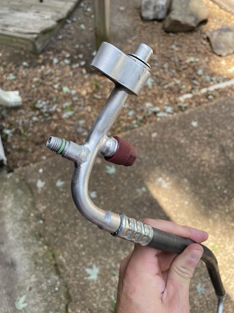
I gotcha. I was currently running with a mix of GM wiring and also the toyota amplifier setup. Im getting a high pressure port braised onto my high pressure line tomorrow and going to run a GM pressure transducer and wire it in the PCM and bypass everything in the AC Amplifier besided the Low pressure switch circuit if possible. Ive got to look at the ewd. I havent had any issues so far with how mine is running, but it recently stopped turning my fans on with the AC button and its stopped increasing revs when the AC button was pressed, so im thinking that this will remedy that. It will basically just run like the tahoe/silverado AC System
- Thread starter
- #156
Hello All, if you are following along in this thread, i have updated Post #79 in the thread with much much more detail for wiring up and operating the AC system for Gen3 motors to ensure you will have PCM controlled idle up and fan operation. It seems like a little extra work but its not too bad.
If you were following along, please read the updated post as there was one step left out and the process is completely detailed now.
Thanks
Link:
Post #79 (Wiring Part 7. Gen 3 AC Idle up and Electric fan control via PCM)
If you were following along, please read the updated post as there was one step left out and the process is completely detailed now.
Thanks
Link:
Post #79 (Wiring Part 7. Gen 3 AC Idle up and Electric fan control via PCM)
I gotcha. I was currently running with a mix of GM wiring and also the toyota amplifier setup. Im getting a high pressure port braised onto my high pressure line tomorrow and going to run a GM pressure transducer and wire it in the PCM and bypass everything in the AC Amplifier besided the Low pressure switch circuit if possible. Ive got to look at the ewd. I havent had any issues so far with how mine is running, but it recently stopped turning my fans on with the AC button and its stopped increasing revs when the AC button was pressed, so im thinking that this will remedy that. It will basically just run like the tahoe/silverado AC System
Hello All, if you are following along in this thread, i have updated Post #79 in the thread with much much more detail for wiring up and operating the AC system for Gen3 motors to ensure you will have PCM controlled idle up and fan operation. It seems like a little extra work but its not too bad.
Looks like the 99-02 5.3s (I have a 2000) have a simpler setup, no electronic fan to worry about and no pressure sensors, just the simple on/off pressure switches. Like yourself I ended up wiring in the GM PCM control because I wanted the idle up and proper handling of both high/low pressure conditions and didn't like the slight stumble when kicking on the system with just the amp turning on the compressor directly. The little bit of extra wiring is well worth it IMHO.
Edited my previous post to note I have an 00 motor for clarity and not to confuse those who have later motors and looking for guidance.
Great thread BTW!
- Thread starter
- #158
Thanks man! I appreciate it. Yeah you definielty have the nicer one to wire up, and you even have the high pressure switch in your compressor already there! Wish i didnt have to get my custom lines redone haha. The earlier AC compressors use the high and low switches to control and the later ones use the pressure sensor. Good catch, need to add that to the post now too! haha Totally agree on the extra wiring. Just takes a few hours but totally worth it!Looks like the 99-02 5.3s (I have a 2000) have a simpler setup, no electronic fan to worry about and no pressure sensors, just the simple on/off pressure switches. Like yourself I ended up wiring in the GM PCM control because I wanted the idle up and proper handling of both high/low pressure conditions and didn't like the slight stumble when kicking on the system with just the amp turning on the compressor directly. The little bit of extra wiring is well worth it IMHO.
Edited my previous post to note I have an 00 motor for clarity and not to confuse those who have later motors and looking for guidance.
Great thread BTW!

Thanks for the detailed write up. About to start on this journey with my 62. Do you have any additional pics of how you handled the trans crossmember - brackets on the frame and mods to the adapter/holes?
Similar threads
Users who are viewing this thread
Total: 6 (members: 0, guests: 6)