Dual Gauge Pod - Install (1 Viewer)

This site may earn a commission from merchant affiliate
links, including eBay, Amazon, Skimlinks, and others.

boydmick

RIP My Friend
SILVER Star
Joined
Dec 4, 2003
Threads
36
Messages
812
Location
The OC
After installing the TRD Supercharger I wanted a way to track the boost and water temp.

I searched extensively and found that a dual gauge pod from an Acura Integra would fit with some modifications; but nobody documented the modifications very well.

Hopefully this will help others who might want dual gauges on an 80.

PARTS:

94-01 Acura Integra 2 door Dual Pod - Tan # ATM-20112 $31.90
VDO Vision series Boost Gauge # 150-101 $32.50
VDO Vision Series Engine Temp Gauge # 310-105 $25.55
Temp sender # 323-419 $9.41

Assorted wire and tubing on hand


TOOLS:
Basic hand tools
Drill/ drill bits
Assorted files (round/flat)
1/2-14 NPT tap
Hacksaw or bandsaw
Shop-vac
Heat gun or :princess: blowdryer

GAUGE POD:

Gently pull the weatherstrip from the A-pillar and leave dangling.
Remove the assist handle (2 phillips screws) and trim (2 clips) from the A-pillar.
Place the gauge pod on the trim to test the fit. The gauge pod is about 1/2 inch wider than the A-pillar and will need to be trimmed.

I found that the best fit was to just cover the lower handle hole with the gauge pod, and leave the excess material toward the windshield. I scribed a line on the back of the gauge pod for the area to be removed.

Layout on pod.JPG

I applied several layers of masking tape to the painted surface to prevent srcatches and used a bandsaw to cut along the line. A dremel tool would work nicely or you could use a hacksaw in a pinch.

Remember; you can always cut more off later, so leave a bit of the line on the gauge pod.

After trimming, test fit the gauge pod and trim to the A-pillar. Once you are satisfied that it fits where you want it, remove the gauge pod and trim together as a unit. Turn the trim over and mark the hole for the assist handle.

Carefully drill out the hole for the assist handle. Use files to smooth/deburr the hole and bandsaw cuts.

At this point, reinstall the trim, weatherstrip and gauge pod on the A-pillar. The weatherstrip will hold the pod in place for the next step.

Install the assist handle with just the upper screw and leave slightly loose.
Slowly warm the area around the hole for the assist handle on the gauge pod with the heat gun.

Once warm, press the lower portion of the assist handle into the gauge pod and secure with the screw. The gauge pod will mold itself to the contours of the trim and the assist handle.
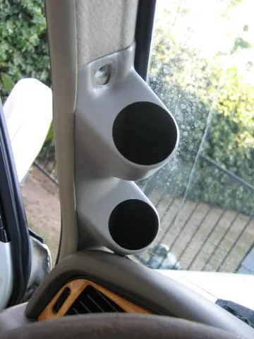
Modified pod.JPG

After you are satisfied with the fit of the gauge pod, you can test fit the gauges.
The gauges for this pod are 2 1/16 inch diameter and are a press fit. They should be very tight in the holes.
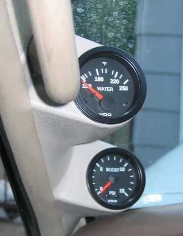
test fit.JPG

To be continued. . .
Layout on pod.JPG
Modified pod.JPG
test fit.JPG
 
Last edited:
Part II - Gauges

PART II - GAUGES:

As mentioned before, the gauges are a press fit in the holes of the gauge pod. I tried not to insert/remove them more than absolutely necessary to avoid loosening the fit.

I initally wanted the water temp gauge on top, but the lower pod has slightly less depth and the boost gauge wouldn't fit. I swapped locations and everything fit fine.

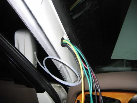
Determine how you want to run the wiring for the gauges. I chose to run them into the A-pillar and down with all the factory wiring. You could just run the wires between the trim and gauge pod out behind the dash; but the wires will push the pod inward and the wires might be visible.

Since I am running the wires through the A-pillar, I needed a hole. Mark the appropriate location on the trim and drill. Be carefull not to rip all of the fabric from the trim as it becomes twisted in the drill bit. Work slowly and cut the fabric with small scissors or a knife as needed.

hole in trim.JPG


Now reinstall the trim and mark the hole on the A-pillar. Remove the trim and drill through the metal.

CAUTION: Be careful to avoid drilling into the factory harness or the drain tube for the sunroof. I used a small pick to move these out of the way while drilling.


I used a rubber grommet to protect the wires from chafing.
hole in pillar.JPG


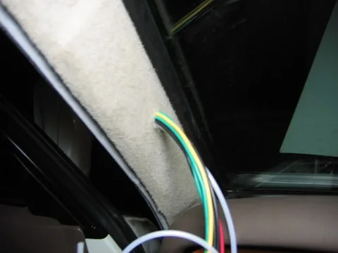
Now the fun part, pulling wires!
Determine the number of wires you will need for your gauges. Pre cut all the pieces (leave them a little long!) then prepare to feed them through the A-pillar.

I ran a stiff piece of bailing wire through the hole and down to the drivers footwell. I determined all the wires I needed, staggered them and taped them onto the bailing wire.
Pull the bailing wire from above and feed the wiring from below.

When finished, it should look like this:

wires pulled.JPG

Stay tuned. . .
hole in trim.JPG
hole in pillar.JPG
wires pulled.JPG
 
Part III - Coming Together

Don't forget to pull the wires through the trim before connecting them to the gauges (don't ask :doh: ):
wires through trim.JPG


Connect all the wires to the gauges. You can see here why I had to move the boost gauge to the top. I guess I could have cut some threads off of the brass fitting, but it fit fine in the top location.
back of pod.JPG


Push the excess wire into the A-pillar, place the pod, install the assist handle and reinstall the weatherstrip.


Here are the gauges in thier final location. One thing you can't see in the photo is that there is a slight gap between the gauge bezel and the gauge pod (~1mm).
finished product.JPG

You could see a little white plastic showing on the temp gauge and a glimmer of silver from the boost gauge.

I popped both gauges out of the pod and drew a band around each gauge with a black marker to help hide the gap. Now it is almost impossible to see; unless you know it's there ;)
wires through trim.JPG
back of pod.JPG
finished product.JPG
 
Part IV - Temperature Sender

After searching the forum :D I chose to install the temperature sender in the water output pipe.

This pipe connects to the block just behind the distributor on the USDS. I removed the distributor cap for easier access.

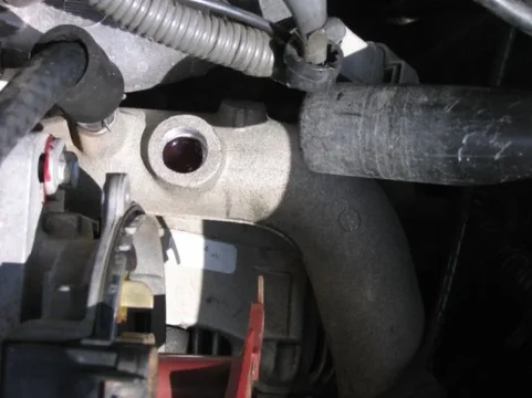
There is a small flat area on top that look like it was designed for a fitting. I carefully drilled holes in increasing diameters until it was large enough for the tap. You can see the hose for the shop-vac I used to keep shavings out of the cooling system.
drilled fitting.JPG


Then it was just a matter of slowly tapping the hole until the threads went all the way through the pipe. Again, I used a shop-vac to suck up all the shavings.
tapped fitting.JPG


Here is the sensor installed in the pipe.
sender installed.JPG


Just for information:

I performed the Raventai gauge mod some time ago. The modified factory gauge and the new Water Temp Gauge are so consistent that I would be comfortable without the additional water temp gauge!! :cool:


Connect up all those loose wires and you are ready to go!!
drilled fitting.JPG
tapped fitting.JPG
sender installed.JPG
 
very nice!! Great job on the install :cheers:
 
Nice write-up. Install looks great. FAQ material.
 
Very clean indeed! Was it easy to remove the A-pillar and did it go back on as well as it was before? Usually, when I take something apart, it never fits as tight as before. How has the Dual Pod worked out so far?
 
The A pillar came off very easily. The weatherstrip and two plastic clips are all that hold it on. Only gentle pressure is needed to pry it off.

It snapped back on just as easily, but I was worried that the additional weight of the gauges would pull the trim back off. Hasn't happened yet.

The only issue I've had so far is a slight buzz/rattle from the boost gauge right as I transition from no boost (vacuum) to very light boost ~.5 psi. I attribute this to the needle vibrating against the stop. Slightly annoying, but livable. a liquid filled gauge would probably solve this, but I'm just nitpicking now.
 
Boyd,

did your VDO boost gauge come with a brass fitting for the engine compartment side of the plastic tubing? I am running an autometer gauge and they only supply a rubber nipple that fits over a plastic T.

It seems like most guys are splicing the boost/vac gauge line into the intake plenum next to the brake fluid reservoir.

The TRD kit suppies you with a small brass plug for the intake plenum which I removed and replaced with a male to male brass fitting that also came with the TRD kit.

However I am having trouble finding a ferrule and cap to install the plastic boost line to the male/male trd supplied fitting.

Any ideas where to get one of these?
 
I honestly can't remember where I got the parts for the engine side of things. I just had to run out to the truck to try to jog my memory.

I vaguely remember buying a tubing kit for the gauge, but I'm not sure. You could probably get the fittings from a hardware store. I'd look in the plumbing or sprinkler section of a Home Depot or Lowes type store.

HTH
 
where does the boost tube get connected to the engine/sc?
 
The 1/8 BSP (British Standard Pipe Thread) nippile on the back of the upper intake manifold. The brake booster hose used to connect to it. Remove it and instead of installing the plug that TRD supplied with the kit, I got an adapter from McMaster Carr. It is a 1/8 BSP male to 1/8 NPT female adapter. The attachments that came with my boost gauges use 1/8 NPT.
 
  • Like
Reactions: RFB
Part IV - Temperature Sender

After searching the forum :D I chose to install the temperature sender in the water output pipe.

This pipe connects to the block just behind the distributor on the USDS. I removed the distributor cap for easier access.

There is a small flat area on top that look like it was designed for a fitting. I carefully drilled holes in increasing diameters until it was large enough for the tap. You can see the hose for the shop-vac I used to keep shavings out of the cooling system.
View attachment 104254


Then it was just a matter of slowly tapping the hole until the threads went all the way through the pipe. Again, I used a shop-vac to suck up all the shavings.
View attachment 104255


Here is the sensor installed in the pipe.
View attachment 104256


Just for information:

I performed the Raventai gauge mod some time ago. The modified factory gauge and the new Water Temp Gauge are so consistent that I would be comfortable without the additional water temp gauge!! :cool:


Connect up all those loose wires and you are ready to go!!
View attachment 104254View attachment 104255View attachment 104256
where did you install the tubing for SC boost pressure?
 
where did you install the tubing for SC boost pressure?
never mind I got it. great write up still works after all these years.
 
I'm glad someone bumped this, thread I plan on doing my pod mounting today
 
  • Like
Reactions: RFB
Looks like the tan gauge pods are discontinued, can anyone recommend a rattle can paint that is close to matching that factory color on the a-post trim?
 
Looks like the tan gauge pods are discontinued, can anyone recommend a rattle can paint that is close to matching that factory color on the a-post trim?

Did you find one in another color?
 
I did that setup a couple years ago. My pod was a freebie from someone else's project that changed plans, so he gave me the pod. It goes all the way up to the top of the A pillar. I could of shortened it, but I liked the way it is secured by the grab handle. I run an EGT and a combo vacuum/boost gauge. Vac tells you how hard your pushing the motor when your NOT in boost.
 

Users who are viewing this thread

Back
Top Bottom