Curtice
SILVER Star
Looks awesome! I have this and am planning the install. Still need to paint my tub, but trying to get all necessary holes, etc drilled first. I’ll probably install the switch somewhere in the dash.
Where did you mount the control panel? In the glove box? I think I’m going to mount it on the underside of the glove box (next to my 3FE ECU.
I’ve wondered if it’s possible to reprogram the RPM scale. I assumed it wasn’t something I could do, but thought about calling them and asking if I sent it in.
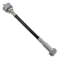
Last question is the VSS. I’ve read your post and others, but still a bit confused. For my engine (1992 3FE) and ECU, I know that the VSS was in the speedometer and connected to the ECU with a signal of 4 pulses per revolution. With this engine in my FJ40, I don’t have this. Can I assume I can install the Dakota Digital VSS and program it to send the correct signal?
Thanks again - been reading your build thread today. It’s been great as I am also planning an in tank fuel pump.
Where did you mount the control panel? In the glove box? I think I’m going to mount it on the underside of the glove box (next to my 3FE ECU.
I’ve wondered if it’s possible to reprogram the RPM scale. I assumed it wasn’t something I could do, but thought about calling them and asking if I sent it in.
Last question is the VSS. I’ve read your post and others, but still a bit confused. For my engine (1992 3FE) and ECU, I know that the VSS was in the speedometer and connected to the ECU with a signal of 4 pulses per revolution. With this engine in my FJ40, I don’t have this. Can I assume I can install the Dakota Digital VSS and program it to send the correct signal?
Thanks again - been reading your build thread today. It’s been great as I am also planning an in tank fuel pump.

")

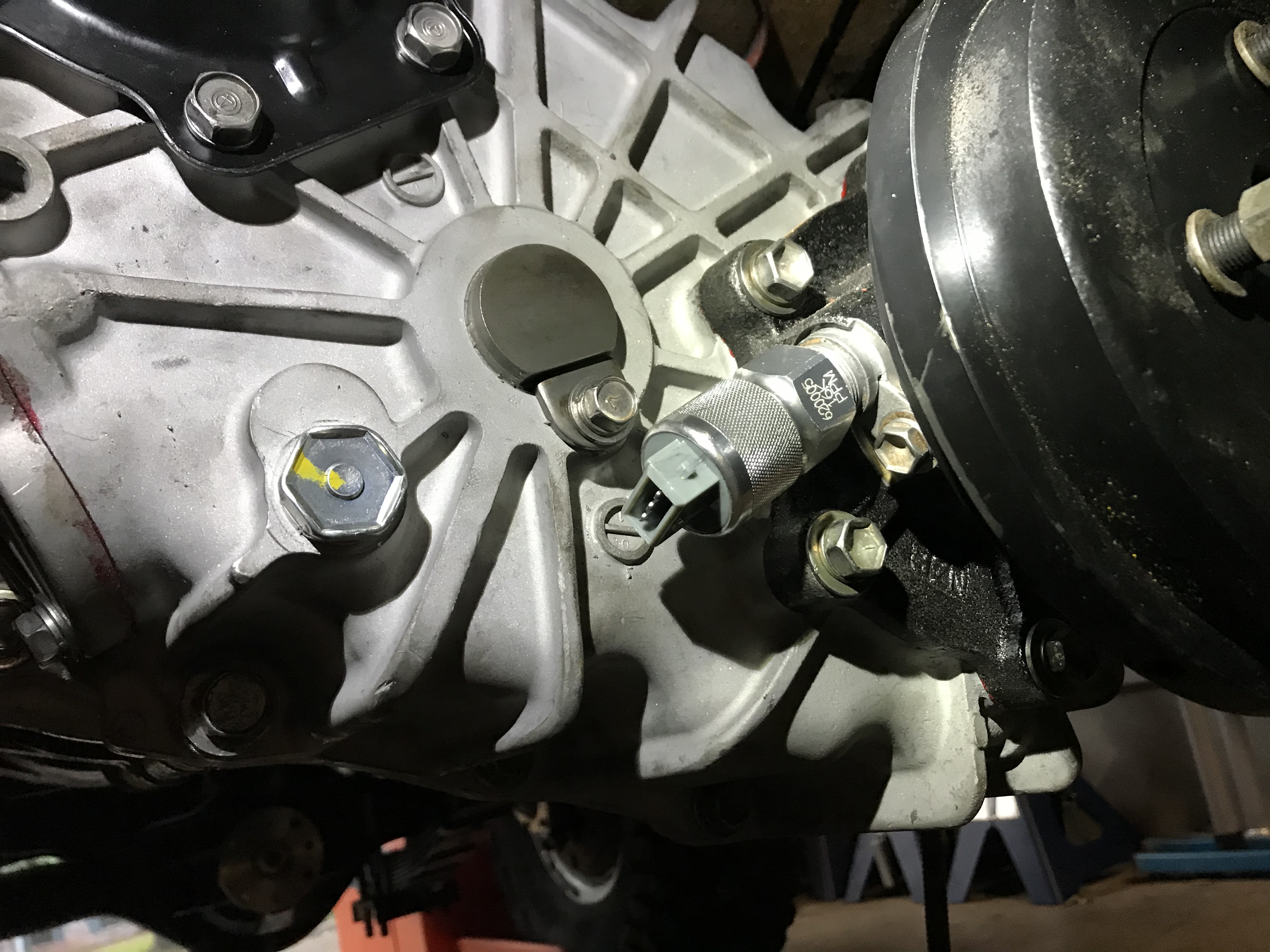
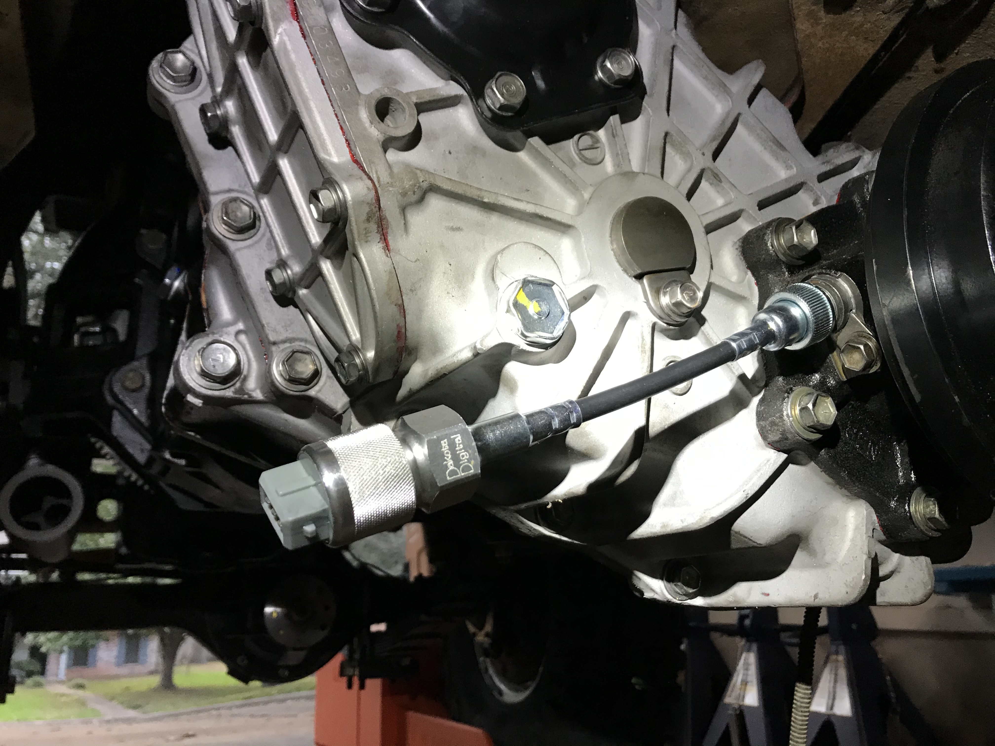
 . It actually didn’t take a lot of force to get it in there. It’s nice and snug and all buttoned up now.