Rudi, please note in the pictures of post #130 & #131 where it says 12V from ignition, there is nothing there. No pin, no wire in the plug. I'm confused how the 12V gets to the cluster. Thanks.barrel connector part 2
Below you see pics of a 3rd and a 4th generation cluster.
Altough the PCB looks (and is) different, the barrel connectors and their connections are identical.
3rd gen. cluster.
View attachment 638149
4th gen. cluster.
View attachment 638150
This cluster was almost fried due to some fooling around with the AMP meter by the PO. I had to bridge 7 (SEVEN!) tracks to get it back to work.
Rudi
Navigation
Install the app
How to install the app on iOS
Follow along with the video below to see how to install our site as a web app on your home screen.
Note: This feature may not be available in some browsers.
More options
Style variation
You are using an out of date browser. It may not display this or other websites correctly.
You should upgrade or use an alternative browser.
You should upgrade or use an alternative browser.
Clusters, Gauges, Speedo & Odo meters
- Thread starter bj40green
- Start date
This site may earn a commission from merchant affiliate
links, including eBay, Amazon, Skimlinks, and others.
More options
Who Replied?I think the confusion is that the plug on the harness is labeled 1 thru 12 with two locations not used (#3 & #10). Then they omit those numbers and end up identifying ten positions, e.g. #4 is Fuel Sender but it is #5 on the plastic plug.barrel connector on the back of the gauge cluster
I had a question from a fellow MUD member today about the pin numbers. The FSM is not 100% clear were pin3 (+12V from ign. key) is.
Here is the barrel connector for 3rd and 4th generation clusters in addition to the FSM.
View attachment 638213
View attachment 638143
View attachment 638144
Rudi
Coolerman
SILVER Star
- Joined
- Jan 5, 2004
- Threads
- 143
- Messages
- 6,766
- Location
- Paint Lick, KY
- Website
- www.globalsoftware-inc.com
Rudi, I just used your diagrams to create a sub-harness that adapted a late model gauge cluster to a 72 harness. I too was confused by the labeling. Don't know why Toyota skipped the numbers. In my world of process control, when documenting a circuit, you NEVER skip numbers in a connector. It confuses people! 
Inspection putty in aircraft. It is applied to a variety of items. My experience of course is in tooling. So when inspection checks a feature on a tool during a "routine" inspection, he applies an inspection putty. Some types of inspection putty are just what you said, nail polish, something that is hard and brittle so that if disturbed it is obvious. Others are a slow setting putty and after application the inspector embosses his stamp.The Voltage Regulator
So the FUEL and TEMP gauge work on 7 Volt but where is that coming from?
In the picture below you'll see the VR on the left.
A wire wound resistor is wrapped around a bi-metal switch (It's the same principle as for the gauge needles).
The resistor heats up, the bi-metal strip bends and the switch opens. The current flow stops, the bi-metal strip cools down and the switch is closed and this process repeats itself. Now here is the kicker..... heating up/opening and cooling down/closing takes each ± 1 second or so. So one second 12 Volt, one second 0 Volt means an average of 6 Volts or when the engine is running 50% of 14 Volts is 7 Volts.
This 7Volts is the value the FSM (posting #7 pages 12-27 and 12-28) is speaking of and also says:
[QUOTE:] -Caution- Do not check the 7V terminal at 12V or 24V. [END QUOTE] because you'll measure only an intermittent 0 and 12Volt.
This "switching" behaviour is also responsible for the "flashing" of the light bulb when you test the FUEL or TEMP gauge with a test light as per the FSM (see posting #7 page 12-26 of the FSM).
View attachment 588214
If you look at the pic in the previous post you can see an adjustment screw on the rights side of the "breaker" points. Here you can adjust the interval time for the VR. The problem is that you can do this only when you have it all apart and in a test situation on your work bench. I don't see the need to change this setting unless your gauges are really off spec. BTW the screw is sealed/fixed with a greenisch ....... I call it "nail polish" but if somebody knows the right word, please tell me.
Rudi
I am looking for a 10 pin round connector, anyone have one?
Looking for a source for the little nylon gear in Early speedos (through 72+) that runs from the worm gear to the number wheel. I need 3-5, but two would get me started.
Maybe a part number?
Maybe a part number?
Great thread, it really helped me out. I lost fuel and temp when I hit a set of rumble bars last weekend. I actually saw the needles drop. Good voltage going in, and no voltage coming out. I just took the cluster apart and everything looked great. There's a little adjustable screw on the back of the fuel gauge and that touches a little contact point, and there was no continuity between the two. I took a tiny piece of emery cloth and gave both faces one little swipe. Put it back together and now I've got both gauges again.
bj40green
Tssss, tssss
- Thread starter
- #490
Great thread, it really helped me out. I lost fuel and temp when I hit a set of rumble bars last weekend. I actually saw the needles drop. Good voltage going in, and no voltage coming out. I just took the cluster apart and everything looked great. There's a little adjustable screw on the back of the fuel gauge and that touches a little contact point, and there was no continuity between the two. I took a tiny piece of emery cloth and gave both faces one little swipe. Put it back together and now I've got both gauges again.
You fixed the internal voltage regulator

Rudi
Just posted in the Stuck Odometer thread.
Stuck Odometer Fix
Stuck Odometer Fix
Thanks for the great info. Helped me fix the fuel and temp gauges on my new to me 77 40.
Looking for a source for the little nylon gear in Early speedos (through 72+) that runs from the worm gear to the number wheel. I need 3-5, but two would get me started.
Maybe a part number?
You might try to make the gears via 3D printing. I've no experience doing this personally but check it out. From what I've read, it just might be the perfect route for small production plastic items such as this.
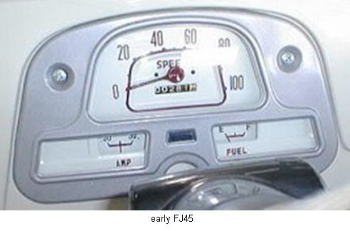
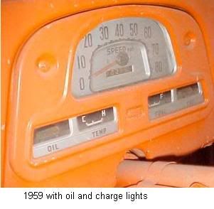
The 1st generation; from 1959 till March ’69
These clusters were pretty basic. An OIL pressure light, TEMP gauge, FUEL gauge and a CHARGE light.
http://i1112.photobucket.com/albums...s clusters fronts/1959withoilchargelights.jpg
Rudi
Great thread. Anyone have the wiring diagram for this type cluster? With the Oil and Charge Lights? Do they light only if high or low pressure and charge?
63cruiser
SILVER Star
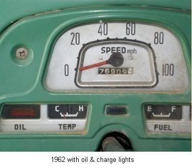
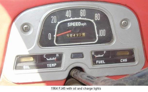
New to the forum but i can't seem to find a answer to this after pouring through tons of posts. I am purchasing a 1963 FJ40 FST. I see that 1962 had the white speedo face and 1964 had the black face but what was original to the 1963? It has currently has a black face. It has sqaure cut doors, titled as a 1963 with a 3 in front on the vin# so...truly a 63 from what i can tell.
New to the forum but i can't seem to find a answer to this after pouring through tons of posts. I am purchasing a 1963 FJ40 FST. I see that 1962 had the white speedo face and 1964 had the black face but what was original to the 1963? It has currently has a black face. It has sqaure cut doors, titled as a 1963 with a 3 in front on the vin# so...truly a 63 from what i can tell.
I don't think a definitive answer exists. Much like the stamped bezel, consensus knowledge suggests that the silver-faced speedometer ended sometime in the 1963 produciton run. But no one seems to know exactly when, or with what vin. Yet another early cruiser mystery.
Hey guys I'm new to the forum and just got my hands on a 74 FJ not too long ago. I'm curious if anybody can help me out with identifying what the four prongs go to on my headlamp pull knob. I broke the piece down but couldn't figure out where each went to. Any help is much appreciated. Cheers.

Similar threads
Users who are viewing this thread
Total: 1 (members: 0, guests: 1)