Builds Blender, My LX450/FZJ80 + FJ45esk + GM + Land Rover crazy concoction (1 Viewer)

This site may earn a commission from merchant affiliate
links, including eBay, Amazon, Skimlinks, and others.

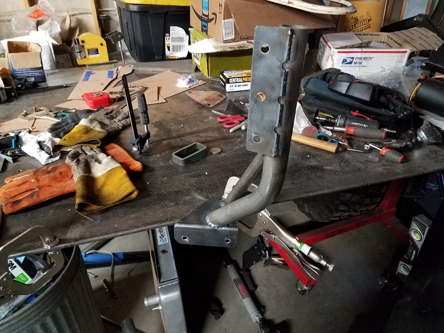
Today was a challenge on the #LX45. I haven't done much exhaust tubing work, but I put my ducks in a row and made it happen. This is all 2.25 inch mandrel bent cut to fit and tig welded. The astute will notice my 3d printed layout cheater blocks with the top secret mailing tube straight section simulation option. The flanges where off eBay. Overall I am pretty happy with how it turned out even though it killed most of the day. I need my engine harness to show up so I can measure for the o2 bung placement. Tomorrow I will start on the passenger side....


The thicker horizontal bar should be on top.
(I'm embarrassed sounding like a nit-pick)

So if it doesn't have the stamped letters....do we really care?
With the opening shifted to the top more air clears the winch.
 
So if it doesn't have the stamped letters....do we really care?
With the opening shifted to the top more air clears the winch.

People will eventually tell you to flip your bezel because it’s upside down.

Up to you though.

Bezel Mounting
 
I care not how you mount your bezel...super work on the exhaust. That would've taken me a week at best, lol!
 
It was like groundhog day on the #LX45. Got up and worked on the exhaust all day. Passenger side is now done other than the o2 bung.


One note....

The aluminum belly pan is working out nice. I had to pull it to remove the passenger side of the Y-pipe. This was pretty easy by myself while laying on my back and just using my knee to hold up the panel. Pretty simple, I hope I can keep it that way.

Hopefully my aluminum square stock shows up for the skidplate ribs soon. I also need to make the front support arm by the oil pan.

Never a shortage of things to do.
 
Updates....


Added some tabs for the rear of the belly pan. These are just little sections of box tube I cut out, made one for each side. These will get clip nuts too for final assembly.


I needed to add some support for the front of the belly pan. This area is pretty protected by the radius arms, but some extra support was needed. There isn't any extra room on the passenger side because of the high pinion differential and driveshaft. I decided to use the old mounting bolts on the frame from the front swaybar link attachment on the frame side. I made an 1/8" thick pad to fit that bolt pattern....


This is what I came up with to connect point A to B. The main tube is 1.5" x 0.120 wall tubing with a bend to connect to the frame pad. I was also able to sneak a 1" tube in there for a bit of extra support. The skidplate tab uses the same 10mm clip nuts at everything else on the belly pan.


This is where it fits. I wish there was room to bridge it all the way to the passenger rail, but there just isn't. I don't think this area of the belly pan will see THAT much abuse, but it should be plenty strong overall.


I finished dressing the seams from all the grill mods down. I'm wondering if I should just blast all the paint off this thing. I really want to paint this before it goes back on since it is integrated into the cooling system stuff basically. If I get it painted it won't have to come back off...

Of course my aluminum for the ribs was wrong, gonna have to send that back. I can move forward without it honestly, but I am approaching the point I need my engine/trans harness soon. I will probably pull the transmission crossmember, mounts, etc out for powder coat to kill a few days.
 
Opps....forgot the shop tip.


If you need a handle on something, tig'n on some filler rod works really well. This stuff is pretty dang strong, yet easy to clip off and sand flush. I was trying to keep my little end cap disc from falling in the tube when tacking it. It was made from a slice of 1.25" bar stock and kept falling in the dang tube.

I'm wondering if you could make dent puller pins like this?
 
Ok. I think I have a TIG welding problem. I can't stop TIG welding stuff on the #LX45. I finished welding up the seams on the tunnel. Now to add a few future proof things like making some shift boot bezels with weld nuts and some hold down stuff for the rubber floor mat idea I have...

 
I think that is the first step... admitting you have a problem.
 
Just trying to sort through some details while I wait for some parts to show up....


I am adding some big pins made out of some capped 1.5 tubing to the inside wall of the rocker guards. This will let me quickly hook a strap eye to the side of the vehicle if needed to stabilize the vehicle or set up a winch trolley.


I made some chipboard templates for the shift boot mounting patterns. The pattern is transferred to the tunnel and I will be adding some weld nuts to the tunnel for these.....but saving the pattern templates so I can make the shift boot ring to the exact same pattern.


I've been cutting end caps for the tubing from solid bar stock. These end up being about .010 small for the ID because the tubing is only .120 wall. So basically they will fall in the hole. Holding them in position is a pain in the butt, so I decided to try a few things....

This seemed to work pretty well. You use two pieces of tig filler ( thinner the better ) to set the cab in place. Then just pull the wires out and tap the cap level if it pulls from the tack weld. Generally this sets the gap to the filler thickness which is pretty nice for a full pen weld.

That is all for now...
 
Just a few things....


I did some future proofing on the tunnel tonight with a lot of weld nuts for the shifter boots. I think this style of weld nut is more durable and easier to install than the caged nut system. I like buying the longer ones with more thread length. You can always trim them down pretty easy once they are tacked in place if you have an interference issue.


Mini shop tip. If you use a screw with a tapered head when you are putting in the weld nuts it centers them perfectly in the hole for the spot welds.


How the pins on the inside of the rocker guards work. It was an easy add and they are tucked completely out of the way. I really wanted a few more possible recovery points on this rig, BUT I wanted them hidden, low profile, and out of the way.
 
you said......Mini shop tip. If you use a screw with a tapered head when you are putting in the weld nuts it centers them perfectly in the hole for the spot welds.

Great tip. Do you find it better to use stainless or standard in regard to heating too much and not coming out easily?
 
Just a bit tonight...


I made templates for the rubber floor mats that will be on the tunnel with mounting holes. Then transferred that information over to the tunnel and added all the weld nuts needed. The amount of weld nuts in this thing is getting silly at this point....


I also fixed a section of the tunnel that had a little oil can going on after the final welding. I did a little shrinking to firm things up. This area will be under a rubber floor mat, but the less noises the better. I use a MAP gas torch to heat up an area about the size of a silver dollar to a quarter. I don't find the need to go red, but rather firmly into the rainbow color change. If possible you want to heat the convex side of the can, but either will work. I use compressed air to cool the heat effected zone. You need to cool the convex side of oil can. If you do the opposite you will get a bad bump in the panel.

Try not to heat the same area twice if you can help it. I use spots about 2-3" apart on the 1st pass. If more is needed I split the difference on the next pass with heat.

The color marks will come off with a scotchbrite pad if needed.
 

Users who are viewing this thread

Back
Top Bottom